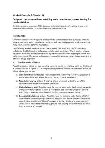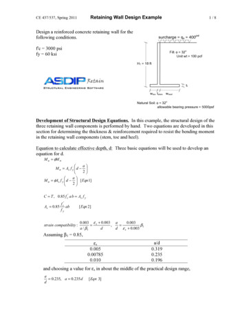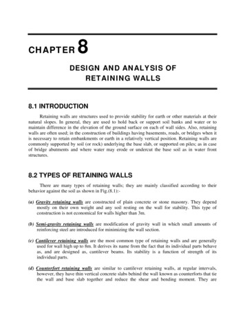
Transcription
Chapter 730Retaining Walls and Steep Reinforced Slopes730.01 GeneralExhibit 730-4 Summary of Nongravity Wall Options Available730.02 ReferencesExhibit 730-5 Summary of Anchored Wall Options Available730.03 Design PrinciplesExhibit 730-6 Other Wall/Slope Options Available730.04 Design Requirements730.05 Guidelines for Wall/Slope SelectionExhibit 730-7 Typical Mechanically Stabilized Earth GravityWalls730.06 Design Responsibility and ProcessExhibit 730-8 Typical Prefabricated Modular Gravity Walls730.07 DocumentationExhibit 730-9 Typical Rigid Gravity, Semigravity Cantilever,Nongravity Cantilever, and Anchored WallsExhibit 730-1 Summary of Mechanically Stabilized EarthGravity Wall/Slope Options AvailableExhibit 730-10 Typical Rockery and Reinforced SlopesExhibit 730-11 MSE Wall Drainage DetailExhibit 730-2 Summary of Prefabricated Modular Gravity Wall Exhibit 730-12 Retaining Walls with Traffic BarriersOptions AvailableExhibit 730-13 Retaining Wall Design ProcessExhibit 730-3 Summary of Rigid Gravity and Semigravity Wall Exhibit 730-14 Retaining Wall Design Process: ProprietaryOptions Available730.01 GeneralThe function of a retaining wall is to form a nearly vertical face through confinement and/or strengthening of amass of earth or other bulk material. Likewise, the function of a reinforced slope is to strengthen the mass ofearth or other bulk material such that a steep (up to 1H:2V) slope can be formed. In both cases, the purposeof constructing such structures is to make maximum use of limited right of way. The difference between the twois that a wall uses a structural facing, whereas a steep reinforced slope does not require a structural facing.Reinforced slopes typically use a permanent erosion control matting with low vegetation as a slope cover toprevent erosion. (See the Roadside Manual for more information.)To lay out and design a retaining wall or reinforced slope, consider the following items: Functional classificationHighway geometryDesign Clear Zone requirements (seeChapter 1600)Amount of excavation requiredTraffic characteristicsConstructabilityImpact to adjacent environmentallysensitive areasImpact to adjacent structuresPotential added lanes Length and height of wallMaterial to be retainedFoundation support and potential fordifferential settlementGroundwaterEarthquake loadsRight of way costsNeed for construction easementsRiskOverall costVisual appearanceIf the wall or toe of a reinforced slope is to be located adjacent to the right of way line, consider the spaceneeded in front of the wall/slope to construct it.WSDOT Design Manual M 22-01.20September 2021Page 730-1
Chapter 730Retaining Walls and Steep Reinforced Slopes730.01(1) Retaining Wall ClassificationsRetaining walls are generally classified as gravity, semigravity, nongravity cantilever, or anchored. The variouswall types and their classifications are summarized in Exhibit 730-1 through Exhibit 730-6.a) Gravity WallsGravity walls derive their capacity to resist lateral soil loads through a combination of deadweight and sliding resistance. Gravity walls can be further subdivided into rigid gravity walls,prefabricated modular gravity walls, and mechanically stabilized earth (MSE) gravity walls.Rigid gravity walls consist of a solid mass of concrete or mortared rubble, and they use theweight of the wall itself to resist lateral loads.Prefabricated modular gravity walls consist of interlocking soil or rock-filled concrete, steel, orwire modules or bins (such as gabions). The combined weight resists the lateral loads from thesoil.MSE gravity walls use strips, bars, or mats of steel or polymeric reinforcement to reinforce thesoil and create a reinforced soil block behind the face. The reinforced soil block then acts as aunit and resists the lateral soil loads through the dead weight of the reinforced mass. MSE wallsmay be constructed as fill walls, with fill and reinforcement placed in alternate layers to create areinforced mass, or reinforcement may be drilled into an existing soil/rock mass using groutedanchor technology to create a reinforced soil mass (soil nail walls).b) Semigravity WallsSemigravity walls rely more on structural resistance through cantilevering action of the wallstem. Generally, the backfill for a semigravity wall rests on part of the wall footing. The backfill,in combination with the weight of the wall and footing, provides the dead weight for resistance.An example of a semigravity wall is the reinforced concrete wall provided in the Standard Plans.c) Nongravity Cantilever WallsNongravity cantilever walls rely strictly on the structural resistance of the wall in which verticalelements of the wall are partially embedded in the soil or rock to provide fixity. These verticalelements may consist of piles (such as soldier piles or sheet piles), caissons, or drilled shafts. Thevertical elements may form the entire wall face or they may be spanned structurally usingtimber lagging or other materials to form the wall face.d) Anchored WallsAnchored walls derive their lateral capacity through anchors embedded in stable soil or rockbelow or behind all potential soil/rock failure surfaces. Anchored walls are similar to nongravitycantilevered walls except that anchors embedded in the soil/rock are attached to the wall facingstructure to provide lateral resistance. Anchors typically consist of deadman or grouted soil/rockanchors.Reinforced slopes are similar to MSE walls in that they also use fill and reinforcement placed inalternate layers to create a reinforced soil mass. However, the face is typically built at a 1.2H:1Vto 1H:2V slope.Rockeries (rock walls) behave to some extent like gravity walls. However, the primary functionof a rockery is to prevent erosion of an oversteepened but technically stable slope. Rockeriesconsist of large, well-fitted rocks stacked on top of one another to form a wall. An example of arockery and reinforced slope is provided in Exhibit 730-10.WSDOT Design Manual M 22-01.20September 2021Page 730-2
Chapter 730Retaining Walls and Steep Reinforced Slopes730.02 References730.02(1) Federal/State Laws and CodesWashington Administrative Code (WAC) 296-155, Safety standards for construction work730.02(2) Design GuidanceBridge Design Manual, M 23-50, WSDOTStandard Plans for Road, Bridge, and Municipal Construction (Standard Plans), M 21-01, WSDOTPlans Preparation Manual, M 22-31, WSDOTRoadside Manual, M 25-30, WSDOT730.03 Design PrinciplesThe design of a retaining wall or reinforced slope consists of the following principal activities: Develop wall/slope geometryProvide adequate subsurface investigationEvaluate loads and pressures that will act on the structureDesign the structure to withstand the loads and pressuresDesign the structure to meet aesthetic requirementsEnsure wall/slope constructibilityCoordinate with other design elementsThe structure and adjacent soil mass also needs to be stable as a system, and the anticipated wall settlementneeds to be within acceptable limits.730.04 Design Requirements730.04(1) Wall/Slope GeometryWall/slope geometry is developed considering the following: Geometry of the transportation facility itselfDesign Clear Zone requirements (see Chapter 1600)Flare rate and approach slope when inside the Design Clear Zone (see Chapter 1610)Right of way constraintsExisting ground contoursExisting and future utility locationsImpact to adjacent structuresImpact to environmentally sensitive areasFor wall/slope geometry, also consider the foundation embedmentand type anticipated, which requires coordination between the various design groups involved.Retaining walls are designed to limit the potential for snagging vehicles by removing protruding objects (such asbridge columns, light fixtures, or sign supports).WSDOT Design Manual M 22-01.20September 2021Page 730-3
Chapter 730Retaining Walls and Steep Reinforced SlopesProvide a traffic barrier shape at the base of a new retaining wall constructed 12 feet or less from the edge ofthe nearest traffic lane. The traffic barrier shape is optional at the base of the new portion when an existingvertical-faced wall is being extended (or the existing wall may be retrofitted for continuity). Depending on theapplication, precast or cast-in-place Single Slope Concrete Barrier with vertical back or Type 4 Concrete Barriermay be used for both new and existing walls except when the barrier face can be cast as an integral part of anew wall. Design analyses may be considered, but they require approval as prescribed in Chapter 300. A designanalysis is not required where sidewalk exists in front of the wall or in other situations where the wall face isotherwise inaccessible to traffic.730.04(2) Investigation of SoilsAll retaining wall and reinforced slope structures require an investigation of the underlying soil/rock thatsupports the structure. Chapter 610 provides guidance on how to complete this investigation. A soilinvestigation is an integral part of the design of any retaining wall or reinforced slope. The stability of theunderlying soils, their potential to settle under the imposed loads, the usability of any existing excavated soilsfor wall/reinforced slope backfill, and the location of the groundwater table are determined through thegeotechnical investigation.730.04(3) Geotechnical and Structural DesignThe structural elements of the wall or slope and the soil below, behind, and/or within the structure are designedtogether as a system. The wall/slope system is designed for overall external stability as well as internal stability.Overall external stability includes stability of the slope the wall/reinforced slope is a part of and the localexternal stability (overturning, sliding, and bearing capacity). Internal stability includes resistance of thestructural members to load and, in the case of MSE walls and reinforced slopes, pullout capacity of the structuralmembers or soil reinforcement from the soil.730.04(3)(a) ScourAt any location where a retaining wall or reinforced slope can be in contact with water (such as a culvert outfall,ditch, wetland, lake, river, or floodplain), there is a risk of scour at the toe. This risk must be analyzed. Contactthe HQ Geotechnical Office and HQ Hydraulics Office to determine whether a scour analysis is required.730.04(4) Drainage DesignOne of the principal causes of retaining wall/slope failure is the additional hydrostatic load imposed by anincrease in the water content in the material behind the wall or slope. This condition results in a substantialincrease in the lateral loads behind the wall/slope since the material undergoes a possible increase in unitweight, water pressure is exerted on the back of the wall, and the soil shear strength undergoes a possiblereduction. To alleviate this, adequate drainage for the retaining wall/slope needs to be considered in the designstage and reviewed by the region Materials Engineer during construction. The drainage features shown in theStandard Plans are the minimum basic requirements. Underdrains behind the wall/slope need to daylight atsome point in order to adequately perform their drainage function. Provide positive drainage at periodicintervals to prevent entrapment of water.Native soil may be used for retaining wall and reinforced slope backfill if it meets the requirements for theparticular wall/slope system. In general, use backfill that is free-draining and granular in nature. Exceptions tothis can be made depending on the site conditions as determined by the Geotechnical Office of theHeadquarters (HQ) Materials Laboratory.WSDOT Design Manual M 22-01.20September 2021Page 730-4
Chapter 730Retaining Walls and Steep Reinforced SlopesA typical drainage detail for a gravity wall (in particular, an MSE wall) is shown in Exhibit 730-11. Includedrainage details with a wall unless otherwise recommended to be deleted by the Region Materials Engineer orHQ Geotechnical Office.730.04(5) AestheticsRetaining walls and slopes can have a pleasing appearance that is compatible with the surrounding terrain andother structures in the vicinity. To the extent possible within functional requirements and cost-effectivenesscriteria, this aesthetic goal is to be met for all visible retaining walls and reinforced slopes.Aesthetic requirements include consideration of the wall face material, top profile, terminals, and surface finish(texture, color, and pattern). Where appropriate, provide planting areas and irrigation conduits. These willvisually soften walls and blend them with adjacent areas. Avoid short sections of retaining wall or steep slopewhere possible.In higher walls, variations in slope treatment are recommended for a pleasing appearance. High continuouswalls are generally not desirable from an aesthetic standpoint, because they can be quite imposing. Considerstepping high or long retaining walls in areas of high visibility. Plantings may be considered between wall steps.Approval by the State Bridge and Structures Architect is required on all retaining wall aesthetics, includingfinishes, materials, and configuration (see Chapter 950).730.04(6) ConstructabilityConsider the potential effect that site constraints might have on the constructability of the specific wall/slope.Constraints to be considered include but are not limited to site geometry, access, time required to construct thewall, environmental issues, and impact on traffic flow and other construction activities.730.04(7) Coordination With Other Design Elements730.04(7)(a) Other Design ElementsRetaining wall and slope designs are to be coordinated with other elements of the project that might interferewith or impact the design or construction of the wall/slope. Also consider drainage features; utilities; luminaireor sign structures; adjacent retaining walls or bridges; concrete traffic barriers; and beam guardrails. Locatethese design elements in a manner that will minimize the impacts to the wall elements. In general, locateobstructions within the wall backfill (such as guardrail posts, drainage features, and minor structurefoundations) a minimum of 3 feet from the back of the wall facing units.Greater offset distances may be required depending on the size and nature of the interfering design element. Ifpossible, locate these elements to miss reinforcement layers or other portions of the wall system. Conceptualdetails for accommodating concrete traffic barriers and beam guardrails are provided in Exhibit 730-12.Where impact to the wall elements is unavoidable, the wall system needs to be designed to accommodate theseimpacts. For example, it may be necessary to place drainage structures or guardrail posts in the reinforcedbackfill zone of MSE walls. This may require that holes be cut in the upper soil reinforcement layers or thatdiscrete reinforcement strips be splayed around the obstruction. This causes additional load to be carried in theadjacent reinforcement layers due to the missing soil reinforcement or the distortion in the reinforcementlayers.WSDOT Design Manual M 22-01.20September 2021Page 730-5
Chapter 730Retaining Walls and Steep Reinforced SlopesThe need for these other design elements and their impacts on the proposed wall systems are to be clearlyindicated in the submitted wall site data so the walls can be properly designed. Contact the HQ Bridge andStructures Office (or the Geotechnical Office for geosynthetic walls/slopes and soil nail walls) for assistanceregarding this issue.730.05 Guidelines for Wall/Slope SelectionWall/slope selection is dependent on: Whether the wall/slope will be located primarily in a cut or fill (how much excavation/shoring will berequired to construct the wall or slope).If located in a cut, the type of soil/rock present.The need for space between the right of way line and the wall/slope or easement.The amount of settlement expected.The potential for deep failure surfaces to be present.The structural capacity of the wall/slope in terms of maximum allowable height.The nature of the wall/slope application.Whether or not structures or utilities will be located on or above the wall.Architectural requirements.Overall economy.730.05(1) Cut and Fill ConsiderationsDue to the construction technique and base width required, some wall types are best suited for cut situations,whereas others are best suited for fill situations. For example, anchored walls and soil nail walls have soilreinforcements drilled into the in-situ soil/rock and are therefore generally used in cut situations. Nongravitycantilevered walls are drilled or cut into the in-situ soil/rock, have narrow base widths, and are also well suitedto cut situations. Both types of walls are constructed from the top down. Such walls are also used as temporaryshoring to allow other types of walls or other structures to be constructed where considerable excavation willotherwise be required.MSE walls and reinforced slopes, however, are constructed by placing soil reinforcement between layers of fillfrom the bottom up and are therefore best suited to fill situations. Furthermore, the base width of MSE walls istypically on the order of 70% of the wall height, which requires considerable excavation in a cut situation.Therefore, in a cut situation, base width requirements usually make MSE structures uneconomical and possiblyunconstructible.Semigravity (cantilever) walls, rigid gravity walls, and prefabricated modular gravity walls are free-standingstructural systems built from the bottom up, but they do not rely on soil reinforcement techniques (placementof fill layers with soil reinforcement) to provide stability.These types of walls generally have a narrower base width than MSE structures (on the order of 50% of the wallheight). Both of these factors make these types of walls feasible in fill situations as well as many cut situations.Reinforced slopes generally require more room overall to construct than a wall because of the sloping face, butthey typically are a feasible alternative to a combination wall and fill slope to add a new lane. Reinforced slopescan also be adapted to the existing ground contours to minimize excavation requirements where fill is placed onan existing slope. Reinforced slopes might also be a feasible choice to repair slopes damaged by landslide activityor deep erosion.WSDOT Design Manual M 22-01.20September 2021Page 730-6
Chapter 730Retaining Walls and Steep Reinforced SlopesRockeries are best suited to cut situations as they require only a narrow base width, on the order of 30% of therockery height. Rockeries can be used in fill situations, but the fill heights they support need to be kept relativelylow. It is difficult to get the cohesive strength needed in granular fill soils to provide minimal stability of the soilbehind the rockery at the steep slope typically used for rockeries in a cut (such as 1H:6V or 1H:4V).The key considerations in deciding which walls or slopes are feasible are the amount of excavation or shoringrequired and the overall height. The site geometric constraints are defined to determine these elements.Another consideration is whether or not an easement will be required. For example, a temporary easementmight be required for a wall in a fill situation to allow the contractor to work in front of the wall. For walls in cutsituations, especially anchored walls and soil nail walls, a permanent easement may be required for the anchorsor nails.730.05(2) Settlement and Deep Foundation Support ConsiderationsSettlement issues, especially differential settlement, are of primary concern in the selection of walls. Some walltypes are inherently flexible and can tolerate a great deal of settlement without suffering structurally. Other walltypes are inherently rigid and cannot tolerate much settlement. In general, MSE walls have the greatestflexibility and tolerance to settlement, followed by prefabricated modular gravity walls. Reinforced slopes arealso inherently very flexible. For MSE walls, the facing type used can affect the ability of the wall to toleratesettlement. Welded wire and geosynthetic wall facings are the most flexible and the most tolerant tosettlement, whereas concrete facings are less tolerant to settlement. In some cases, after the wall settlement iscomplete, concrete facing can be placed such that the concrete facing does not limit the wall’s tolerance tosettlement. Facing may also be added for aesthetic reasons.Semigravity (cantilever) walls and rigid gravity walls have the least tolerance to settlement. In general, totalsettlement for these types of walls needs to be limited to approximately 1 inch or less. Rockeries also cannottolerate much settlement, as rocks can shift and fall out. Therefore, semigravity cantilever walls, rigid gravitywalls, and rockeries are not used in settlement prone areas.If very weak soils are present that will not support the wall and are too deep to be overexcavated, or if a deepfailure surface is present that results in inadequate slope stability, select a wall type capable of using deepfoundation support and/or anchors. In general, MSE walls, prefabricated modular gravity walls, and some rigidgravity walls are not appropriate for these situations. Walls that can be pile-supported, such as concretesemigravity cantilever walls, nongravity cantilever walls, and anchored walls, are more appropriate for thesesituations.730.05(3) Feasible Wall Heights and LimitationsFeasible wall heights are affected by issues such as the capacity of the wall structural elements, past experiencewith a particular wall, current practice, seismic risk, long-term durability, and aesthetics.For height limitations, see Exhibit 730-1 through Exhibit 730-6.730.05(4) Supporting Structures or UtilitiesNot all walls are acceptable to support other structures or utilities. Issues that are to be considered include thepotential for the wall to deform due to the structure foundation load, interference between the structurefoundation and the wall components, and the potential long-term durability of the wall system. Using retainingwalls to support other structures is considered to be a critical application, requiring a special design.WSDOT Design Manual M 22-01.20September 2021Page 730-7
Chapter 730Retaining Walls and Steep Reinforced SlopesIn general, soil nail walls, semigravity cantilever walls, nongravity cantilever walls, and anchored walls areappropriate for use in supporting bridge and building structure foundations. In addition to these walls, MSE andprefabricated modular gravity walls may be used to support other retaining walls, noise walls, and minorstructure foundations such as those for sign bridges and signals. On a project-specific basis, MSE walls can beused to support bridge and building foundations as approved by the HQ Bridge and Structures Office.Consider the location of any utilities behind the wall or reinforced slope when making wall/slope selections. Thisis mainly an issue for walls that use some type of soil reinforcement and for reinforced slopes. It is best not toplace utilities within a reinforced soil backfill zone because it will be impossible to access the utility from theground surface without cutting through the soil reinforcement layers, thereby compromising the integrity of thewall.Sometimes utilities, culverts, pipe arches, and so on must penetrate the face of a wall. Not all walls and facingsare compatible with such penetrations. Consider how the facing can be formed around the penetration so thatbackfill soil cannot pipe or erode through the face. Contact the HQ Bridge and Structures Office for assistanceregarding this issue.730.05(5) Facing OptionsFacing selection depends on the aesthetic and structural needs of the wall system. Wall settlement may alsoaffect the feasibility of the facing options. More than one wall facing may be available for a given system.Consider the available facing options when selecting a particular wall.730.05(5)(a) MSE WallsFor MSE walls, facing options typically include: Precast modular panels.In some cases, full height precast concrete panels. Full height panels are generally limited to walls with amaximum height of 20 feet placed in areas where minimal settlement is expected.Welded wire facing.Timber facing.Shotcrete facing with treatment options that vary from a simple broom finish to a textured and coloredfinish.Segmental masonry concrete blocks.Cast-in-place concrete facing with various texturing options.Plantings on welded wire facings can be attempted in certain cases. The difficulty is in providing a soil at the wallface that is suitable for growing plants and meets engineering requirements in terms of soil compressibility,strength, and drainage. If plantings in the wall face are attempted, use only small plants, vines, and grasses.Small bushes may be considered for plantings between wall steps. Larger bushes or trees are not considered inthese cases due to the loads they can create on the wall face.Geosynthetic facings are not acceptable for permanent facings due to potential facing degradation whenexposed to sunlight. For permanent applications, use some type of timber, welded wire, or concrete face forgeosynthetic walls. Shotcrete, masonry concrete blocks, cast-in-place concrete, welded wire, or timber aretypically used for geosynthetic wall facings.WSDOT Design Manual M 22-01.20September 2021Page 730-8
Chapter 730Retaining Walls and Steep Reinforced Slopes730.05(5)(b) Soil Nail WallsSoil nail walls can use either architecturally treated shotcrete or a cast-in-place facia wall textured as needed toproduce the desired appearance.730.05(5)(c) Prefabricated Modular Gravity WallsFor prefabricated modular gravity walls, the facing generally consists of the structural bin or crib elements usedto construct the walls. For some walls, the elements can be rearranged to form areas for plantings. In somecases, textured structural elements might also be feasible. This is also true of rigid gravity walls, though plantingareas on the face of rigid gravity walls are generally not feasible. The concrete facing for semigravity cantileverwalls can be textured as needed to produce the desired appearance.730.05(5)(d) Nongravity Cantilevered WallsFor nongravity cantilevered walls and anchored walls, a textured cast-in-place or precast facia wall is usuallyinstalled to produce the desired appearance.730.05(6) Cost ConsiderationsUsually, more than one wall type is feasible for a given situation. Consider initial and future maintenance coststhroughout the selection process, as the decisions made may affect the overall cost. For example, you may haveto decide whether to shut down a lane of traffic to install a low-cost gravity wall system that requires moreexcavation room or use a more expensive anchored wall system that will minimize excavation requirements andimpacts to traffic. In this case, determine whether the cost of traffic impacts and more excavation justifies thecost of the more expensive anchored wall system. Consider long-term maintenance costs when determining walltype.Decisions regarding aesthetics can also affect the overall cost of the wall system. In general, the least expensiveaesthetic options use the structural members of the wall as facing (welded wire or concrete or steel cribbing orbins), whereas the most expensive aesthetic options use textured cast-in-place concrete facias. In general,concrete facings increase in cost in the following order: shotcrete, segmental masonry concrete blocks, precastconcrete facing panels, full height precast concrete facing panels, and cast-in-place concrete facing panels.Special architectural treatments usually increase the cost of any of these facing systems. Special wall terracingto provide locations for plants will also tend to increase costs. Therefore, weigh the costs against the value ofthe desired aesthetics.Other factors that affect the costs of wall/slope systems include wall/slope size and length; access at the site anddistance to the material supplier location; overall size of the project; and competition between wall suppliers. Ingeneral, costs tend to be higher for walls or slopes that are high, but short in length, due to lack of room forequipment to work. Sites that are remote or have difficult local access increase wall/ slope costs. Smallwall/slope quantities result in high unit costs. Lack of competition between materials or wall system supplierscan result in higher costs as well.Some of the factors that increase costs are required parts of a project and are therefore unavoidable. Alwaysconsider such factors when estimating costs because a requirement may not affect all wall types in the sameway. Current cost information can be obtained by consulting the Bridge Design Manual or by contacting the HQBridge and Structures Office.WSDOT Design Manual M 22-01.20September 2021Page 730-9
Chapter 730Retaining Walls and Steep Reinforced Slopes730.05(7) SummaryFor wall/slope selection, consider factors such as the intended application; the soil/ rock conditions in terms ofsettlement, need for deep foundations, constructibility, and impacts to traffic; and the overall geometry in termsof wall/slope height and length, location of adjacent structures and utilities, aesthetics, and cost. Exhibit 730-1through Exhibit 730-6 provide a summary of many of the various wall/slope options available, including theiradvantages, disadvantages, and limitations. Note that specific wall types in the exhibits may represent multiplewall systems, some or all of which will be proprietary.730.06 Design Responsibility and Process730.06(1) GeneralThe retaining walls available for a given project include standard walls, nonstandard walls, and reinforcedslopes.Standard walls are those walls for which standard designs are provided in the Washington State Department ofTransportation (WSDOT) Standard Plans. These designs are provided for reinfo
timber lagging or other materials to form the wall face. d) Anchored Walls . WSDOT Design Manual M 22-01.20 Page 730-4 September 2021 Provide a traffic barrier shape at the base of a new retaining wall constructed 12 feet or less from the edge of the nearest traffic lane. The traffic bar
