Transcription
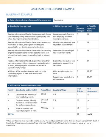
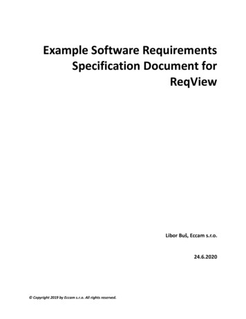
Worked Example 2 (Version 1)Design of concrete cantilever retaining walls to resist earthquake loading forresidential sitesWorked example to accompany MBIE Guidance on the seismic design of retaining structures forresidential sites in Greater Christchurch (Version 2) November 2014IntroductionCantilever concrete retaining walls are commonly used for residential purposes, often asintegral basement walls. Usually the cantilever wall stem is of concrete block constructionrising from an in-situ concrete foundation.The following worked example is for a free-standing cantilever wall that is consideredsufficiently flexible for active soil pressures to be used for design. Where used as integralbasement walls they are often buttressed by return walls and floor diaphragms which maymake them too stiff for active soil pressures to develop requiring higher design loads and adifferent design approach.1.1Possible modes of failurePossible modes of failure for free-standing concrete cantilever retaining walls are illustratedin cartoon fashion in Figure X.1. A complete design should address each of these modes offailure where appropriate.a) Wall stem structural failure: The wall stem fails in bending. Most likely location isat the base of the wall where the stem connects to the foundation.b) Foundation bearing failure: A bearing failure of the soil under the toe of thefoundation and a forwards rotation of the wall.c) Sliding failure of wall: Possible mode for non-cohesive soils. Wall moves outwardswith passive failure of soil in front of foundation and active failure of soil behindwall. Often a key is required beneath the foundation to prevent sliding.d) Deep seated rotational failure: Possible mode for cohesive soils. Factor of safetycontrolled by increasing length of heel or depth of key. Factor of safety calculatedusing limiting equilibrium “Bishop” analysis or similar. Unlikely to govern designunless wall is embedded into sloping ground with sloping backfill or there is a weaklayer at the toe of the wall.1
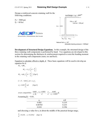
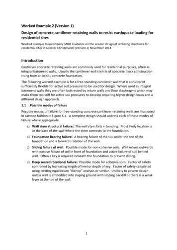
Figure X.1. Possible modes of failure for free-standing concrete cantilever retaining walls.The following worked example uses a simplified LRFD design procedure with load andresistance factors taken from B1/VM4. It is considered suitable for common residentialsituations with competent soils.This procedure is intended to be readily calculated by hand, although use of calculationsoftware such as Mathcad or Excel will be useful for design iterations. The examplecalculations are made here using Mathcad.1.2Example WallFigure X.2. Concrete cantilever wall example.The example wall is shown in Figure X.2. The wall is assumed to be located in theChristchurch Port Hills. The following design assumptions were made:Soil type:Port Hills loessStrength parameters:c 0, φ 30 degreesDrained strength parameters for Port Hills loess were assumed for the long term, gravityonly load case. For the earthquake load case, the foundations in loess were designed2
assuming undrained strength, c 50 KN/m2, φ 0 degrees. (Following therecommendations given in the Guidelines).Wall situation:Case 3: Retaining wall downslope and supporting dwellingfoundationsSurcharge:The surcharge from the dwelling was assumed to be 5 kN/m2averaged across the active soil wedge for the gravity case and 4 kN/m2 for the earthquakecase. Surcharge should be calculated using:ω 1.2 G 0.4 Q for the gravity caseω G 0.3 Q for the earthquake case.Seismic parameters:𝐶(𝑇) 𝐶ℎ (𝑇)𝑍𝑍𝑍(𝑇, 𝐷)Ch(T)Equation (1.1) from Guidelines1.33 for Class C assuming shallow soil siteZ 0.3 for Christchurch for ULSR Return period factor 1.0 for Importance Level 2 walls, ULSN(T,D) Near fault factor which may be taken 1.0 for residential retaining wallsC(T) 0.3 x 1.33 0.4C(T,Atopo) C(T)AtopoEquation (1.2) from GuidelinesAtopo 1.0 assuming site is not near cliff edge or ridge topC(T,Atopo) 0.4 x 1.0 0.4kh C(T,Atopo)WdEquation (1.3) from GuidelinesWd wall displacement factor, given in Table 2 from Guidelines as 0.5 (refer to Table 1 forwall case, then Table 2 for Wd)kh 0.4 x 0.5 0.2Note that by adopting Wd 0.5 it is implicitly assumed that the wall and the retained groundare likely to yield and accumulate permanent displacement during the design earthquake.Wall elements must be sufficiently resilient and/or ductile to accommodate thedisplacement. Some settlement of retained material behind the wall should also beexpected following an earthquake.Step 1. Initial trial geometryThe main variables for geometry are the length of the toe, the length of the heel, and thedepth of the key. These will be refined during the analysis below. The thickness of the wallstem and footing should be refined during the structural design process. The optimumlocation for the key is at the end of the heel, as shown in Figure X.2. The analytical modelused for the design is illustrated in Figure X.3.3
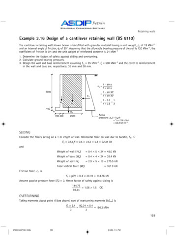
Figure X.3. Analytical model used for gravity design of free-standing concrete cantilever wall(moments taken about point O).4
Step 2. Foundation bearing (gravity case)The foundation bearing capacity (gravity case) will usually govern the design of the walldimensions and is checked first. The soil under the toe of the foundation in particular isworking very hard to resist the vertical bearing loads, sliding shear, and to provide passiveresistance to sliding.For the following simplified procedure, the “middle third rule” is applied, whereby the wallfoundation is dimensioned so that the resultant vertical force acts through the “middlethird” of the footing. If the “middle third rule” is not applied, then a more rigorous analysisof the bearing capacity of the wall foundation should be undertaken.The bearing capacity of the foundation must be calculated taking into account the effect ofsimultaneous horizontal loads applied to the foundation from the soil pressure (i.e. byapplying load inclination factors), and using the reduced, effective width of the foundationfrom the eccentricity of the resultant vertical load. Where there is confidence in theproperties of the soil backfill in front of the toe of the footing, then the net horizontal loadconsidered when calculating the load inclination factors for the bearing capacity may bereduced by the passive soil force acting against the footing (refer to Brinch-Hansen 1970), inwhich case the depth factors must be set to 1.0 (i.e. the shear strength of the soil above thefounding depth of the footing cannot be counted twice).In the worked example, the passive soil resistance has been neglected (conservatively) whencalculating the load inclination factors and bearing capacity, as follows.5
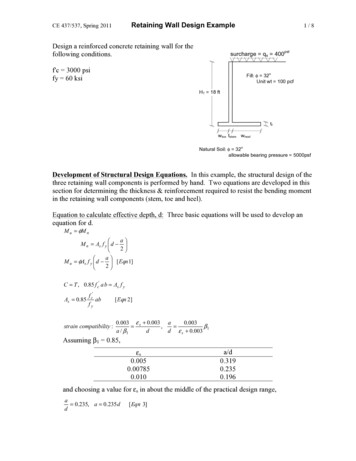
Figure X.4. Parameter definition.(Note: A chart giving values of Ka and Kp based on the log-spiral solutions of Caquot andKerisel is appended to this example).6
Note that the vertical component of active thrust is not factored (i.e. α 1). The horizontalcomponent of active thrust is factored (α 1.5) to account for uncertainty of soil properties.But, uncertainty in soil properties does not significantly affect the vertical component whichwill remain about the same even if the actual soil friction angle is less than assumed.The self-weight components are here factored down (α 0.9) to account for uncertaintybecause they are “stabilising” in this context, even though contributing to the vertical loadon the footing.7
Detailed bearing capacity calculations are appended, and give the following result:Vstar Vu therefore bearing capacity OK for gravity case.Step 3. Wall sliding (gravity case)The sliding analysis is carried out with reference to the model shown in Figure X.3. Theweight of the block of soil underneath the footing and mobilised by the key is included inthe calculation of base friction, Vs. All of the self-weight components are here factoreddown (α 0.9) to account for uncertainty because they are “stabilising” in this context.The vertical component of active thrust is not factored (i.e. α 1), as before. The verticalcomponent of passive resistance is also not factored (i.e. α 1) because it is “de-stabilising”in this context.Factored resistance factored load therefore OK.Step 4. Wall stem bending strength (gravity case)The wall stem may fail in bending. The maximum bending moment will be at the base of thestem and may be calculated using the analytical model shown in Figure X.5. The surchargeabove the heel is included as a worst case. The calculation of the bending strength of thewall should be carried out in accordance with the relevant material code.8
Figure X.5. Analytical model for calculating bending moment in wall stemThe bending capacity of the wall stem under action Mu needs to be checked using therelevant material code.Step 5. Foundation bearing (earthquake case)The foundation bearing capacity is checked for the earthquake case using the samegeometry developed for the gravity case and including the earthquake inertia loads fromthe self-weight of the wall and from the soil above the heel according to the analyticalmodel shown in Figure X.6.9
Figure X.6. Analytical model for earthquake case.For the earthquake case, the undrained shear strength of the foundation soil may beassumed for Port Hills loess when calculating the passive soil resistance. For the example, Su 50 KN/m2 was assumed. The passive soil distribution is shown in Figure X.6 with thecohesive contribution 2 c where c Su and Kp 1 for φ 0.Where the ground surface immediately in front of the wall is exposed, the passive resistancemay be ineffective near to the ground surface because of desiccation and cracking anddisturbance during excavation of the footing. For the example, the cohesive component ofpassive resistance was neglected down to the base of the concrete footing. For othersituations where the ground surface is protected by pavement it may be appropriate toinclude the cohesive component of passive soil resistance over the full depth ofembedment, using judgement.Using the same simplified procedure as for the gravity case, the “middle third rule” is againchecked.The bearing capacity of the foundation, again, must be calculated taking into account theeffect of simultaneous horizontal loads applied to the foundation from the soil pressure (i.e.by applying load inclination factors), and using the reduced, effective width of thefoundation from the eccentricity of the resultant vertical load. For the earthquake case, theLRFD parameters are all set to unity, as discussed in the guidelines, assuming that the loessfoundation soil will not be subject to strength loss during earthquake shaking or strainsoftening as a result of soil yielding.10
The inertia of the wall structural elements and soil located above the heel (treated as part ofthe wall) are added, as follows:The restoring moment from the self-weight of the wall and soil above the heel is calculatedas follows without any load factor applied.11
So the line of action of the net vertical force on the wall footing is still within the “middlethird”.Detailed bearing capacity calculations are appended, and give the following result:Vstar Vu therefore bearing capacity OK for earthquake case.Step 6. Wall sliding (earthquake case)The sliding analysis is carried out with reference to the model shown in Figure X.3. Thecohesive component of passive soil resistance in front of the toe of the wall was neglectedbecause of possible desiccation and disturbance. None of the components of load orresistance are factored for the earthquake case.12
Hstar Hueq therefore design OKStep 7. Wall stem bending strength (earthquake case)The wall stem may fail in bending. The maximum bending moment will be at the base of thestem and may be calculated using the analytical model shown in Figure X.6. In this case theactive earthquake pressure from the soil is added to the inertia of the wall stem. Thecalculation of the bending strength of the wall should be carried out in accordance with therelevant material code.Figure X.6. Analytical model for calculating bendingmoment in wall stem (earthquake case)13
The bending capacity of the wall stem under action Mu needs to be checked using therelevant material code.Detailed bearing capacity calculations:14
15
16
17
References:Bowles, J.E. (1997) Foundation Analysis and Design, Fifth Edition, McGraw-Hill, New York,1175 p.Brinch-Hansen, J (1970). A revised and extended formula for bearing capacity, Bulletin No.28, Danish Geotechnical Institute, Copenhagen.Pender, M J (2015) “Moment and Shear Capacity of Shallow Foundations at Fixed VerticalLoad”. Proc., 12th Australia New Zealand Conference on Geomechanics, Wellington.Vesic, A.S. (1975) Chap. 3, Foundation Engineering Handbook, 1st. Ed., edited by Winterkornand Fang, Van Nostrand Reinhold, 751 p.18
Worked example to accompany MBIE Guidance on the seismic design of retaining structures for residential sites in Greater Christchurch (Version 2) November 2014 . Introduction . Cantilever concrete retaining walls are commonly used for residential purposes, often as integral basement walls. Usually the cantilever wall stem is of concrete block .