Transcription
Formula Student CarDesign ProcessFrom concept to success, step bystep tasks to design a competitiveFormula Student carOptimumG – Vehicle Dynamics Solutions 1
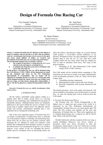
Formula Student TeamManagementTestingTeam ptDrawingSimulationOptimumG – Vehicle Dynamics Solutions 2Assembling
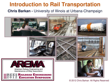
Tips for New TeamsPeople MachinePeople MoneyYear 1:Year 2:Year 3:OptimumG – Vehicle Dynamics Solutions 3A TeamA TeamA TeamC CarB CarA Car
Tips for New Teams FS success well designed car FS success 1. Team 2. Project Management 3. Engineering A good team and a well managed projectare both based on people!OptimumG – Vehicle Dynamics Solutions 4
Year ScheduleOptimumG – Vehicle Dynamics Solutions 5Design4-5 monthsAssembling1-2 monthsTesting4-6 months
Specific Goals Interdependencebetweensubsystems Manufacturing AssemblingTesting General ConceptAssemblingDesignYear Schedule Reliability Validation andUnderstanding Driver skills PerformanceOptimizationOptimumG – Vehicle Dynamics Solutions 6
Goals You should define goals for all three phases.Your goals should be dependent on:– Culture– Experience– Team size– Leadership and organizational skills– Available tools WorkshopIndustrial partnersSoftwareProfessors– BudgetOptimumG – Vehicle Dynamics Solutions 7
Design PhaseOptimumG – Vehicle Dynamics Solutions 8
Initial ConsiderationsBefore starting to design a new car, you shouldgather information/considerations from thefollowing topics: Formula Student competition (rules, tracks,requirements, etc.) Previous cars Main problems and mistakes from previousyearsOptimumG – Vehicle Dynamics Solutions 9
Formula Student CompetitionRulesSpeedsTracksLateral cess to data?What componentsdo we havefreedom with?Access to oldervehicles?OptimumG – Vehicle Dynamics Solutions 10
Rules The rules define the boundaries for your design Must be read completely by all team members The rules should be constantly revisited along thedesign process and along the yearOptimumG – Vehicle Dynamics Solutions 11
Simulation Type FlowchartPoint MassLap Time SimulationBicycle ModelS.S. 4 Wheel ModelLinear InputsS.S. 4 Wheel ModelNon-Linear InputsS.S. 4 Wheel Modelwith ComplianceTransient 4 WheelModelOptimumG – Vehicle Dynamics Solutions 12Vertical ¼, ½, or FullCar Transient ModelYMD
SimulationBefore starting a specific simulation type,guarantee that you have all the necessary toolsand information: The necessary software (commercial or selfmade) and the knowledge on how to use it The necessary information from yourdesign/car (examples: kinematics, aeromap,compliance from FEA or measurement) A clear list of the desired outputs andconclusions when performing a simulationOptimumG – Vehicle Dynamics Solutions 13
Point Mass - Lap Time SimulationInputs MassBasic tire modelBasic engine modelAerodynamic coefficientsTransmission ratiosCircuitOutputs Lap time Speed/accelerationprofile along the circuit Energy ConsumptionConclusions/Decisions Most important parameters among mass, grip, power, and aerodynamics Lap time sensitivity for each of the parameters Lateral/longitudinal grip sensitivityOptimumG – Vehicle Dynamics Solutions 14
Point Mass - Lap Time SimulationMassGripPoint Mass SimulationSensitivitiesPowerAero (Downforce andDrag)Energy ConsumptionOptimumG – Vehicle Dynamics Solutions 15
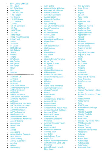
Point Mass - Lap Time SimulationMass Sweep How influent is mass reduction? What is our mass reduction limit? How much would it cost?OptimumG – Vehicle Dynamics Solutions 16
Point Mass - Lap Time SimulationMass and Power Sweep What is more influent, mass or power? Where should we invest our money?OptimumG – Vehicle Dynamics Solutions 17
Bicycle Model - Steady State Additional InputsWheelbaseCG heightMass distributionDownforce distributionOutputs Maximum lateralaccelerationBalance metricControl & Stability metricsLongitudinal weight transferPitchSlip angle / slip ratioSideslip angleConclusions/Decisions Match mass distribution, downforce distribution, and tire selection toachieve the desired car balance Understand how mass distribution, downforce distribution, and tireselection influences grip, balance, control, and stabilityOptimumG – Vehicle Dynamics Solutions 18
4 Wheel Model - Steady State Additional InputsWheel TrackSuspended and nonsuspended massSpring, ARB, and tirestiffnessStatic camber and toeCompliance (optional)Outputs Lateral load transferdistribution Roll and pitch angles Lateral and longitudinalaccelerationsConclusions/Decisions Match spring, ARB, and tire stiffness to achieve the desired car balance withlateral load transfer distribution included Decide spring, ARB, and tire stiffness to provide the desired roll gradientOptimumG – Vehicle Dynamics Solutions 19
4 Wheel Model - Steady StateBalanceOptimumG – Vehicle Dynamics Solutions 20
4 Wheel Model - Steady StateDownforce – Track ReplayOptimumG – Vehicle Dynamics Solutions 21
Non-Linear Kinematics 4 Wheel ModelAdditional Inputs Pickup points OutputsCamber variationToe variationCaster/kingpin variationVSAL (front and sideview)Motion ratiosEtc.Conclusions/Decisions Decide all pickup points of the suspension to provide the desired kinematicgains and motion ratios Iterate with chassis design to guarantee that all pickup points have enoughsupport from chassis (minimize compliance)ICOptimumG – Vehicle Dynamics Solutions 22
Transient Bicycle / 4 Wheel Model Additional InputsYaw inertiaDamper curvesTire relaxation length(optional)Compliance (optional)Outputs LARTYARTYaw velocity dampingControl and stabilityTransient roll and pitchbehaviorConclusions/Decisions Understand how different parameters influence the car transient responsefor lateral, longitudinal, and yaw accelerations Understand how the dampers are controlling roll and pitchOptimumG – Vehicle Dynamics Solutions 23
Transient 4 Wheel ModelTransient Load TransferOptimumG – Vehicle Dynamics Solutions 24
Vertical ¼, ½, or Full Car Transient ModelzsmsAdditional Inputs Tire damping (optional)kscszumuktctzr OutputsTransmissibilityLoad variationHeave/pitch couplingDamper speed histogramBody controlConclusions/Decisions Match spring, tire, and damper stiffness to achieve the desired bodycontrol, load variation, and ratio between suspension and tire compression.Suspension TravelHub TravelPad TravelOptimumG – Vehicle Dynamics Solutions 25
CADOptimumG – Vehicle Dynamics Solutions 26
General AdviceGeneral advice for a formula student car design: Low mass Low yaw inertia Low CG height Small car Low compliance Respect of engineering best practices (no rodend in bending, suspension linkage axis goingthrough chassis node, etc.)OptimumG – Vehicle Dynamics Solutions 27
General AdviceRod end in bendingSuspension linkage axisin the middle of a tubeOptimumG – Vehicle Dynamics Solutions 28
Testing PhaseOptimumG – Vehicle Dynamics Solutions 29
Testing Goals Reliability Validation andunderstandingof the car Driver training Performance optimization (setup)OptimumG – Vehicle Dynamics Solutions 30
Testing Testing – phase with the highest potentialfor improvement of your car’s performance Breaking – you will break things if you testenough Failure Analysis RepairOptimumG – Vehicle Dynamics Solutions 31
Data AcquisitionYou should not only acquire the data, but use it to: Validate and correlate with simulations Understand your vehicle behavior Improve driver skillsKPI Compare different setupsOptimumG – Vehicle Dynamics Solutions 32
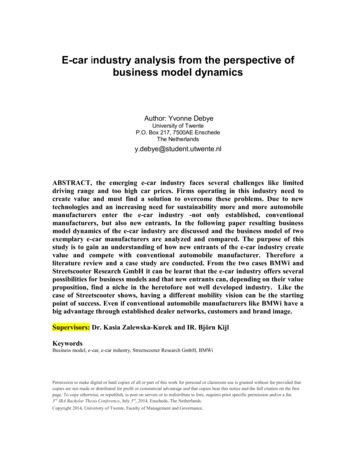
Data AcquisitionKPI Example – Driver ComparisonOptimumG – Vehicle Dynamics Solutions 33
Before Going to the TrackUsing dummy dampersOptimumG – Vehicle Dynamics Solutions 34
Before Going to the TrackUsing dummy dampers1.2.3.4.5.6.7.8.9.Setup with dummy damper at designed eye-to-eye lengthInstall dummy dampersConnect suspension linear (or rotary) potentiometerDo your car setupZero suspension potentiometersRemove dummy dampersPut real spring and damper unit.Reconnect suspension linear (or rotary) potentiometerTurn spring platform to come back to same reference length readfrom the potentiometersOptimumG – Vehicle Dynamics Solutions 35
Before Going to the TrackSetup pad methodology1.Is the chassis and suspensionsstraight? Symmetrical?2.Install dummy dampers3.Fuel and driver ballast.Same corner weights as withoutdummy dampers10. Adjust Toe11.Make sure tire pressure are still on target12.Go to 713.Adjust Corner Weight14.Go to 74.Setup Tire @ hot pressure(unless dummy wheels are used)15.Check Bump Steer using dummy dampersadjustments5.Disconnect ARB16.6.Min Shock setting(unless dummy dampers are used)Place damper and adjust length withspring platform until same as dummydampers ’s length (if using dummy dampers)7.Adjust Ride Height17.Reconnect ARB. Adjust ARB droop linklength to get the same corner weight8.Adjust Caster18.Damper setting9.Adjust Camber18.Wings settingOptimumG – Vehicle Dynamics Solutions 36
Before Going to the TrackKnow your car adjustmentsDummy damper length 305305305305305305310310305305315315305305Ride HeightLF42.5RF42.5LR79.0Motion ratioRR79.0LFRFLRCorner weight (kg)RRLF50.0RF50.0LR55.0Toe (mm)RR55.0LF-2.0RF-2.0Caster (deg)LR1.0RR1.0LF6.7RF6.7LR4.9Camber (deg)RR4.9LF-3.0RF-3.0LR-1.4RR-1.4 By filling up this sheet you will have a good idea of:- Motion Ratio- Camber variation in heave- Bump steer- Caster variation in heave It will help you to notice and trace any possible dissymmetry Be aware that these measurements do not take into account the tire and chassis complianc Worth to validate your kinematics softwareOptimumG – Vehicle Dynamics Solutions 37
Before Going to the TrackSteeringYesNoCommentsWheel centered and securedCheck ListCockpitShaft to pinion bolt nut tightSafety harness bolts secureRack mount bolts tightRack end clevis bolts tightThrottlecableattach tochassisandpedalsecure.Steering arm bolts tightThrottle cable jam nuts secureSteering free lock to lockThrottle stop adjusted and lockedRack roller adjustments lockedClutch stop adjusted and lockedPinion hold down tightBias bar stop nuts locked, bearing freeEnd play checkedMaster cylinder rods free, jam nuts lockedRack end clevises tight and lockedRack length checkedTrack rod jam nuts tightYesNoCommentsYesNoCommentsYesNoCommentsFire extinguisher charged, mounting tightPedal bolts secureFront SuspensionYesNoCommentsHub bearings checked for playAll instruments/switch lines secured andinsulatedShift linkage adjusted, lubed and securedHub retaining bolts torqueMirrors adjusted and secureUpper and lower ball joints checkedSeat secured and lockedUpper and lower ball post nuts tightUpper wishbone attach bolts tightElectricalLower wishbone attach bolts tightBattery fully chargedUpper and lower shock bolts tightBattery connections secure and insulatedSway bar attach bolts tightBattery hold down secureSway bar link bolts tightElectric pumps functioningSway bar centeredTail/brake lights functioning and secureShocks adjusted in bumpShocks adjusted in reboundSpring lockedFront wing adjustedRear suspensionRace tire mounted and pressure setRear substructure attach bolts secureBall joints checked for play, jam nuts tightWheel nuts tight and double checkedHub bearings checked for playHub retaining bolts torqueUpper and lower ball joints checkedFront BrakesYesNew pad sign on steering wheelRace pads installedNoCommentsUpper and lower ball post nuts tightUpper wishbone attach bolts tightLower wishbone attach bolts tightUpper and lower shock bolts tightCaliper bolts tight and wiredSway bar attach bolts tightDiscs centeredSway bar link bolts tightDiscs checked for cranks and run outSway bar centeredBrakes bleed, bleeders tight and dryShocks adjusted in bumpSeals and unions checked under pressureShocks adjusted in reboundMaster cylinder bolts tightSpring locked.Reservoirs full, caps tight, rag in place.Front wing adjustedRace tire mounted and pressure setWheel nuts tight and double checkedOptimumG – Vehicle Dynamics Solutions 38
Before Going to the TrackSetup SheetSponsor BESTEXACT RACINGSET UP NO.EVENTDRIVERRACEMr DRIVERCIRCUITLAP DISTDIFFPLATESRAMPSPRE-LOADHEWLAND SALISBURY2 PLATES45 / 80noneENG. NO / MILESM/C FRONTDISCSBRAKE BIASRATIOSout. .750FtLEFT FRONTTOE.060 insCASTER5.50 TrailCAMBER- 3.50 TIRE PRESS.C12.5HDUCTS50 % openOUTSTD1st15: 3126.00 .750inRrnone50018080FtAP: 30in.250358REV LIM.750Rr .750Solid PADSCMT from full front3rdCWP2110: 29: 31FRONT WINGANGLEGURNEYSKIRTSFtTILT0.00GEOMETRYRIDE HTSPRINGSROLL BARBLADENo antidive1.225 inslb/in19.0fixedISSUED ON:VANCOUVER1.6482ndLow RCFINAL90 4 th73909322DATECHASSISSEPTEMBER 1 ST 2000T00/20-28? milesFUELRACKRAD INLET10 GALLONS6TEETHFULLY OPEN: 255th23 : 2427.00 nonein.750.750out.RrLow RCNo antidive1.225ins500lb/in.590.250x.15090 TOECASTERCAMBERTIRE PRESS.DUCTSX WEIGHTRIGHT FRONT.060insOUT5.50 TrailSTD- 3.00 C13.5H19.050 % openX WEIGHT 20FRONT SHOCKSTypePistonP D 10D14TOECAMBERTIRE PRESS.DUCTSNeedle5 degLEFT REAR.120 ins- 2.20 C12.0H50 % openHSB shStdHS B LSB sh LS B4.0a -6.0R sh.CREB-0.5Gas150RAKE0.725GEOMETRYRIDE HTSPRINGSROLL BARBLADE / ADJHigh RCIN18.0.350TypePistonP D 10 D14Antisquat1.950 ins800lb/inDouble Adjustablex.25045 Needle5 degHigh RC1.950 ins800.350xHSB shStdHS B LSB sh LS B4.0A -6.0AntisquatTOECAMBERTIRE PRESS.DUCTSlb/inx.25090 R sh.CREB-0.5RIGHT REAR.080ins- 1.80 C12.0H50 % openGas150IN18.0REAR SHOCKSTypePistonP D 16L2Needle5 degHSB shStdHS B LSB sh LS B5.0B-6.0R sh.DREB-18Gas180TypePistonP D 16 L 2REAR WINGHOLEGURNEYHOLE 11.875MISCELLANEOUS NOTESNew FWEPOptimumG – Vehicle Dynamics Solutions 39Needle5 degHSB shStdHS B LSB sh LS B5.0B-6.0R sh.DREB-18Gas180
Before Going to the TrackSet DownOptimumG – Vehicle Dynamics Solutions 40
Before Going to the TrackTear DownOptimumG – Vehicle Dynamics Solutions 41
On the TrackSetupSuggested order of parameters to adjust and test on the track: Tire PressureRide HeightEngine TuningBrake icsDifferentialDifferent pickup points Iterate!OptimumG – Vehicle Dynamics Solutions 42
CompetingOptimumG – Vehicle Dynamics Solutions 43
Competing Study all documents provided by thecompetition organization ahead of time Develop a time plan for all activities during thecompetition days. Examples:– When and who is going to each event (design andbusiness presentation, skid pad, acceleration,autocross, endurance)– When to setup the car for each event Leadership and organization are extremelyimportantOptimumG – Vehicle Dynamics Solutions 44
Emotion is your #1 Enemy and #1 FriendThere is nothing wrong with being happy aboutgood results.There is nothing wrong with being sad aboutbad results.There is nothing wrong with emotions. But don’t let theminfluence your decisions, judgment and actions.OptimumG – Vehicle Dynamics Solutions 45
Dealing with Ups and DownsSuccessFailure- Why did it work?- Why didn’t it work?- Identify factors forsuccess- Identify factors forfailure- Celebrate- Regroup andredefineOptimumG – Vehicle Dynamics Solutions 46
Suggested VideoWOT Films: Claude Rouelle, Advice for SAE Teamshttps://youtu.be/c1n-rgqSTyYOptimumG – Vehicle Dynamics Solutions 47
Thank you!Claude RouelleFounder and PresidentOptimumG – Vehicle Dynamics Solutions 486450 South Quebec Street, 5#28Centennial, Colorado 80111 USA 1 303 752 1562www.optimumg.comengineering@optimumg.com
7. Adjust Ride Height 8. Adjust Caster 9. Adjust Camber 10. Adjust Toe 11. Make sure tire pressure are still on target 12. Go to 7 13. Adjust Corner Weight 14. Go to 7 15. Check Bump Steer using dummy dampers adjustments 16. Place damper and adjust length with spring platform until same a