Transcription
Proceedings of the 2016 International Conference on Industrial Engineering and Operations ManagementDetroit, Michigan, USA, September 23-25, 2016Design of a mechanical cleaning device P.I.G (pipelineintervention gadget) connecting two transfer lines inZimbabweTawanda MushiriDepartment of Mechanical EngineeringUniversity of JohannesburgP.O Box APK 524JohannesburgSouth Africatawandanda.mushiri@gmail.com, tawandamushiri123@hotmail.comStephen NdlovuDepartment of Mechanical EngineeringUniversity of ZimbabweP.O Box MP167Mt les MbohwaFaculty of Engineering and the Built EnvironmentUniversity of JohannesburgP.O Box APK 524JohannesburgSouth Africacmbohwa@uj.ac.zaAbstractIn the Oil and Gas Industry, maintenance is done using a device or tool called a pig, chiefly to removesolids, dirt, and liquids from the pipelines. The aim of this work is to design and retrofit a pig which willclean 3 identical underground transfer pipelines linking 2 depots The movement of this tool is basicallythrough the action of the fluid in the pipeline pushing it along as it is pumped from one point to another,hence no external power is needed in the device to help in its movement. Calculation based model analysisof the tool together with Solidworks simulations and results are included in detail, with all assumptions andlimitations clearly stated and listed. The results show that the pig will move inside the pipe at a lower speedthan the mean flow velocity which is good for the performance of the electronic systems installed on itsbody for pipeline inspection. Bypass hole is added on the central part of the pig body to control the speedas well as keep the cleaned dirt stirred and moving, being pushed by the pig as it performs its cleaningprocess.KeywordsPipeline Intervention Gadget, pipeline, design, transfer lines, maintenance IEOM Society International1289
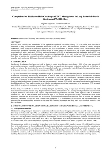
Proceedings of the 2016 International Conference on Industrial Engineering and Operations ManagementDetroit, Michigan, USA, September 23-25, 20161. IntroductionPetroleum as a source of energy powers a vast number of vehicles as well as railway locomotives, aircraft and ships.This means it is highly valuable hence its demand in the global market is very high regardless of it being a nonrenewable energy resource. In Zimbabwe this demand as in other countries keeps increasing and hence the need forcareful transportation since it is an imported product is also crucial. The fuel is transported in a pipeline system whichruns all the way from the Beira port in. To the engineers the challenge is in the servicing and maintenance of theunderground pipelines without disrupting or stopping the flow of the product. According to the ILS Standards use ofpipeline pigs as maintenance tools is the solution to tackling these problems. To define pigging, it is a process in whicha properly sized device, be it spherical or cylindrical is propelled through a pipeline by manipulating the pressure andflow of the existing media (fluid or gas) with the specific purpose of cleaning, inspecting, distributing an inhibitor andor as a plug to isolate a section of the pipeline (Varghese, 2011). A pig now can be defined as a device (or gadget) thatmoves through the inside of a pipeline for the purpose of cleaning, dimensioning, or inspecting (Girard Industries,2015) .Figure 1. A modern smart/intelligent pigA pig can be used in various pipeline industries such as gas or other related fields depending on the nature of jobrequirements, for example; Utility pigs, Inline Inspection tools, gel pigs and plugs. Due to technological advancementspig improvement led to the design of smart pigs, also known as, inline inspection (ILI) tools or intelligent pigs whichare basically electronic devices designed to flow inside of a gas/liquid transmission pipelines, usually while the lineis in service, to inspect a pipeline so as to reduce the risk of pipeline failure (Nagaraj, 7-9 July 2015).1.1 BackgroundEver since the breakthrough in the Petroleum industry in the 19th century, it has grown to successfully dominate theglobal economic market. Engineers in this particular field have had to deal with several challenges so as to optimizecosts and at the same time maximize production and distribution. The use of pipeline technology led to problemswhich resulted in the invention of Pigs. The term Pig has never had a satisfactory explanation as to why it was termedthat way although it is believed it came from the loud, screeching pig-like sounds as the early pigs went through apipeline. On the other hand a theory claims its stands for Pipeline Intervention Gadget.Historically pigging applications were mainly focused in cleaning of pipelines in order to maximize the flowconditions and were basically crude in nature. However in the modern world these applications have spread throughoutdue to various reasons and the equipment for pigging is designed by Engineers so as to perform particular functionsefficiently, reducing cost as much as possible. Also International standards such as the Indian Regulations and API1163 have been adopted for performance checks such as servicing and deciding life span of a pipeline as well as otherapplications. There is need for a mechanism or device to remove dirt accumulating in the interior of the undergroundpipelines as well as detect corrosion, without stopping or interrupting the transfer flow. IEOM Society International1290
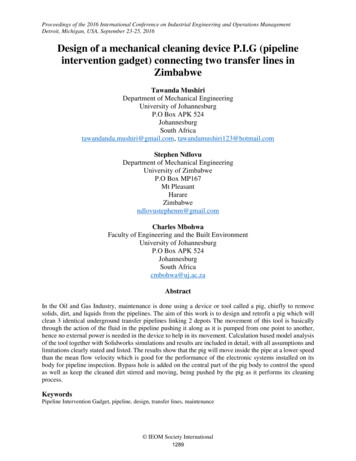
Proceedings of the 2016 International Conference on Industrial Engineering and Operations ManagementDetroit, Michigan, USA, September 23-25, 20162. Literature review2.1 Pigs and their classificationPigs can be classified into different categories according to their manner of job requirement or operations. Theseoperations include removal of debris, cleaning of wax, rust and dirt, tasks such as dewatering prior to commissioning,flooding a pipeline for hydrotest, detecting anomalies and leakages as well as other physical damages as a form ofinspection. The pigs can then be grouped into 3 categories; Utility pigs In-line Inspection Tools Gel pigsUtility PigsThese pigs are basically for cleaning and sealing pipelines, hence, they can be divided into 2 categories.1.2.Cleaning pigs – these are equipped with brushes or blades to remove the dirt which accumulate in the interiorwalls of the pipeline. The dirt can be inform of debris, wax from mainly crude products and so on. In gaspipelines, solvents in the inhibitors evaporate and form solids on pipeline walls which are removed by thesecleaning pigs. Cleaning pigs can also be used in conjunction with chemical treating of lines to disturbcorrosion sites and products, microbes and remove water as well as food for the microbes.Sealing pigs – these may be spheres, solid cast polyurethane or mandrel type pigs used during hydrostatictesting of pipelines. They are also used in separating dissimilar products from a products pipeline and alsoremove water among other applications. The sealing elements are usually elastomer cups or discs used as acombination of both sealing and cleaning elements to remove soft deposits.Figure 2. Utility pigsIn-line Inspection ToolsAlso called ’intelligent’ or ‘smart’ pigs as they provide information about the conditions as well as the extent andlocation of the pipeline problems, which then is used for rehabilitation by the operator and means for regularexamination to maintain a pipeline in good condition. In this paper we shall mainly focus on this type of piggingtogether with existing technologies for the case study and design.ILI technologies include the 2 most preferred methods for detecting and measuring metal loss; magnetic-flux leakage(MFL) and the ultrasonics (U/S).1.Magnetic-flux leakage ILI tools – the basic principle of this type of technology is by using a sensor to recordvariations or leakages of the flux path as the pig travels through the steel pipeline. A permanent magnet with twopoles is fitted on the pig such that its magnetic field is induced in the pipeline wall and a flux path recorded. Thesensor is then placed between the two poles and detect leakages which are directly related to the wall thicknessi.e. areas of metal loss. Sufficient flux density is required to be induced in the pipeline wall meaning very powerfuland often large magnets are used, this limits the use of MFL tools to thin walled pipelines i.e. in gas pipelines. IEOM Society International1291
Proceedings of the 2016 International Conference on Industrial Engineering and Operations ManagementDetroit, Michigan, USA, September 23-25, 20162.Ultrasonics ILI tools – its operation principle is basically the measurement of the time taken by an echo to travelto and fro through the pipeline wall, which is directly related to the wall thickness. A transducer is used to emit apulse of ultrasonic sound which travels at a known speed through the pipeline. U/S tools have a limitation that isopposite to that of MFL tools as they have a minimum thickness for accurate recordings hence they mainly applyultrasonic technology in liquid pipelines.Figure 3. Intelligent pig using MFL technologyGel pigsThese are basically a series of gelled liquid systems, developed to be used in pipeline operations as mechanical pigs.The gel pigs can either work in conjunction with the mechanical pigs for better performance or can be pumped intoany pipeline capable of accepting liquids. There are 3 main types of gel pigs;1.High-viscosity sealing gels – these are visco-elastic and self-healing gels designed for downhole fracturingtechniques with strong cohesive attraction, and used mainly in situations where contamination of the productor pipeline wall is not important.2. Commissioning cleaning gel systems – these gels have a high yield strength, visco-elastic and plastic flowproperties which ensures that the debris remains suspended even if the gel is static for long periods. Cleaninggel pigs are prepared from fresh water or sea water gelled with a biodegradable polymer.3. Hydrocarbon gels – They are used in operational oil or gas pipelines where aqueous systems are unacceptable,either with a mechanical pig or run alone. Gelled hydrocarbons can be mixed as base fluid, giving the highsealing efficiency characteristic of gel pigs.LaunchingThe following procedure to be described is a general guide to pipeline pigging as they vary depending on the pipelinesetup as well as the operation procedures. In some cases or companies, the pig launcher might be left on stream andin some, it is isolated after the pig has been run. IEOM Society International1292
Proceedings of the 2016 International Conference on Industrial Engineering and Operations ManagementDetroit, Michigan, USA, September 23-25, 2016Figure 4. Typical pig launcherThe launcher setup has 3 major valves; kicker valve, trap isolation valve and the main line valve. The other 2 valves,the drain and the vent are fitted on the trap barrel for emptying and pressure balance respectively. The sequence forliquid systems is described as follows;1.2.3.The isolation valve and the kicker valve are closed.The drain valve is opened and air allowed to displace the liquid by opening the vent valve.When the pig launcher is completely drained (0 Pa), with the vent and drain valves still open, the trap(closure) door is opened.4. The pig is installed with the nose firmly in contact with the reducer between the barrel and the nominal boresection of the launcher.5. The closure seal and other sealing surfaces are cleaned, lubricated if necessary, and the closure door closedand secured.6. The drain valve is then closed. By gradually opening the kicker valve and venting through the vent valve, thetrap is slowly filled.7. When filling is complete, the vent valve is closed to allow pressure to equalize across the isolation valve.8. The isolation valve is opened as the pig is ready for launching.9. The main line valve is partially closed, thus increasing the flow through the kicker valve and behind the pig.Continue to close the main line valve until the pig leaves the trap into the main line as indicated by the pigsignaler.10. After the pig leaves the trap and enters the main line, the main line valve is fully opened and both the isolationvalve and the kicker valve closed.11. The pig launching is complete.ReceivingAgain the pig receiver, just like the launcher might either be left on stream or isolated as according to the companypolicies and operation procedures.Figure 5. Typical pig receiver IEOM Society International1293
Proceedings of the 2016 International Conference on Industrial Engineering and Operations ManagementDetroit, Michigan, USA, September 23-25, 2016In this case, the kicker valve is replaced by the bypass valve and the rest of the setup remains unchanged except theprocedure is reverse as compared to the launching.3. MethodologyTo summarize the methodology, the 1st step will be data compilation as the pigging procedure involves, the study ofthe pipeline to be pigged by critical qualitative analysis prior to design. Once this information about the pipeline isobtained, a field survey is carried out for the launching and retrieval setup sites along the pipeline, thus the quantitativedata. Data sheets and schematic drawings of the pipeline are then produced and the pig designed based on thisinformation. The pig design involves prototype drawing and testing using CAD, thus theoretical calculations producedneed to be compared with those produced by the computer so as to optimize and size a final solution which will bethe last step in the design procedure.4.Pipe DatacompilationField survey(pipeanalysis)Pig Data sheet andschematic drawingsPrototypedesignFigure 6. Process flowThe data sheet compiled below is a result of the qualitative collection of pipe information gathered during the visit tothe 2 depots under the study. The information contained will be used for calculations and prototype design of chapter6 and it is specifically for the section of the pipeline to be monitored and cleaned.Table 1. Pipe Input DataPARAMETERSVALUELength of pipeline, LDepot 1 – Depot 2 300 000 l/hrDepot 2 – Depot 1 150 000 l/hr3200 mOutside diameter, D300 mmFlow-rate(s)5 mmThickness, tAverage of 3 mPipe depth from the groundPipe bends5D bendsPipe valvesnonesmoothInterior conditionCarbon steelPipe material60 barsSystem pressure, P4. Results and discussion4.1 DesignNDT technology is currently being utilized in the Pipeline industry through the use of electronic surveying robotscommonly known as intelligent or smart pigs. These metal loss or corrosion detecting techniques through long distancepipelines has been made possible due to advances in microprocessor technology. In this section, a detailed designedof an intelligent pig which utilizes ultrasonic technology will be designed, based on the 12 inch pipelines whichtransfer petroleum products between two depots. The PIG will not only perform metal loss detection, but also clean IEOM Society International1294
Proceedings of the 2016 International Conference on Industrial Engineering and Operations ManagementDetroit, Michigan, USA, September 23-25, 2016the pipelines as defined by the project aims and objectives. This means the design will be carried out in 2 steps, firstlythe mechanical aspect i.e. the pig components sizing and retrofit and then the ultrasonic transducers selected andinstalled on the pig designed.Custom sizes and thicknesses in inches and pounds for pig components are tabulated below;Table 2. Components custom sizesAPipe Size12’’BCTypeApprox.WeightODThicknessCenter HoleGuide disc12.0’’1.0’’1 1/16’’5.0 lbsSealing disc12 ¾’’5/8’’1 1/16’’3.5 lbsSpacer disc7.0’’5/8’’1 1/16’’1.4 lbs12 ¾’’1.0’’1 1/16’’5.0 lbsBrushesFigure 7. Pig design model (not up to scale) in relation to table 2Bolt sizes are 12 mm to 14 mm and the pitch circle diameter for the bolt is 145 mm according to the manufacturerstandards. For bi-directional pigs, the pig can be launched or propelled in either direction inside the pipe hence, one IEOM Society International1295
Proceedings of the 2016 International Conference on Industrial Engineering and Operations ManagementDetroit, Michigan, USA, September 23-25, 2016side is a mirror image of another. This means that the pig design will contain on each side; 1 guide disc, 2 sealingdiscs, 6 spacer dis c and 1 rotary wire brush.4.2 Pig motion analysisBehavior of the bidirectional pig model in steady state motion is analyzed. The working assumptions are listed asfollowing;i.ii.iii.iv.Most friction is due to the sliding contact of the seals and the pipe wall, as most of the pig weight is directedto the seal discs (only true for new pigs when wear is negligible).The analysis is treated as an axi-symmetrical problem i.e., centerline of the pig matches that of the pipelineresulting in uniform distribution of wear, leakage and friction around the seal circumference (in reality weightcauses friction to be greater at the bottom).The pressure drop across the bi-di pig is assumed constant and that pressure drop across seals is equal.The wall force is assumed to be related to real oversize of the sealing and not guide discs as their designoffers zero or little resistance to the flow.Figure 7. Pig Motion AnalysisIt should be noted that the sealing discs are oversized hence when the pig is moving inside the pipeline, they will bendin contact with the pipe wall as indicated by a circle. Flow-rates show that, when fuel is being transferred, due togravitational aid, the flow-rate is greater than the opposite hence for our design, a greater value mean flow will beused for safety. Also greater values of density will be considered for the design i.e. density of diesel at 20o as given bythe company Gasoil specification sheet of October 2015.Q will be taken as 300 000 l/hr 0.083333 m3/s, Density of diesel; ρ 0.8656 kg/l 865.6 kg/m3, Internal diameterof pipeline; d 295mm 0.295m; Contact friction coefficient between polyurethane seals and a steel pipeline is givenby; η 0.6. Leakage flow for pigs is found to be greater than 0.95, hence for this design; kd 0.98 will be selected.Using above figures for pig motion analysis, magnitude of forces, velocities and differential pressure can be calculatedas follows;Drag coefficient of the pig, CDUsing the Kogusi equation; CD 4(kd) 4 / (1- kd2)2 2352.739924 4 (0.98)4 / (1-0.982) 2 2353Cross-sectional area of the pipe, A IEOM Society International1296
Proceedings of the 2016 International Conference on Industrial Engineering and Operations ManagementDetroit, Michigan, USA, September 23-25, 2016𝑑𝑑Using the internal diameter; A π ( )22 π (0.1475)2 0.068349 0.0684m2With the drag coefficient of the pig and the cross-sectional area of the pipe both having been determined, the dragforce, FD on the pig created by the flow can now be calculated.Drag force on the pig, FD A CD 0.0684 2353 160.8258 161NDuring steady state motion, the drag force as calculated above is equal in magnitude but opposite direction to thecontact friction force, Ff.Contact friction force, Ff η N 161, N 161 / 0.6 268.0431 268NWhere, N is the total normal force that the pig exerts on the pipe wall in the radial direction and can be consideredas the weight of the pig. Using this result, the mass of the pig can then be calculated as follows;N mg, m 268/ 9.81, 27.3235, 27.32kgInside the pipe line, the pig moves with a constant velocity, Vp which is less than the mean flow, V due to existenceof contact friction as observed from the above calculations. The difference between these two velocities is equal to anamount Vd i.e. Vp V – Vd.Vd 2𝜂𝜂𝜂𝜂𝐶𝐶𝐶𝐶𝐶𝐶𝐶𝐶 2 0.6 2682353 865.6 0.0683 0.048081 0.0481 m/sSince the mean flow-rate is 0.0833 m3/s the corresponding mean velocity, V 1.219 m/s. using the above result forVd, the pig velocity can then be calculated.Pig velocity in the pipeline, Vp V - Vd 1.219 – 0.0481 1.170918 1.171 m/sPressure difference across the pig can then be calculated, having obtained the velocity of the pig as well as the dragcoefficient.Pressure difference across the pig, ΔPΔP (CD ρ Vd2 ) / 2 (2353 865.6 0.04812) / 2 2352.7399 2353 N/m2Compiling all calculations and tabulating them to form a design specification sheet.Table 3. Technical Data SheetPARAMETERSVALUEGuide disc x2D 305 mm (t 25.4 mm)Sealing disc x4D 324 mm (t 16 mm)Spacer disc x12D 178 mm (t 16 mm)D 324 mm (t 25.4 mm)Brushes x2Mounting/Pig body diameter110 mmBy-pass nose diameter66 mmMass (weight) of pig, m27.32 kg (268N)Overall length of pig, L800 mmLength of pig body400 mm IEOM Society International1297
Proceedings of the 2016 International Conference on Industrial Engineering and Operations ManagementDetroit, Michigan, USA, September 23-25, 20161.711 m/sPig velocity, VPPig differential pressure, ΔP2353 N/mm25%By-pass %3.94%Leakage flow-rate4.3 Design of the ultrasonic pigThis part of the design focuses on utilizing UT technology for metal loss detection. The sensors to be selected in thefollowing section will be installed on the cleaning pig body already designed. After this selection is complete, the twopigs will then be joined together using the universal coupling to form one intelligent and multitasking pig. This willmean the dimensions of the UT pig and the cleaning pig will be the same, only component arrangement and selectionwill be rearranged, thus behavior in the pipeline will be identical.4.3.1 Sensor probe selectionThe ultrasonic transducer to be selected should satisfy the following standard operations for a 12 inch liquid pipeline;o Transducer frequency 3.5 MHzo Transducer focus 165 mmo Minimum measurable thickness 3 mmo Maximum measurable thickness 1 mo Inspection sensitivity 0.1 mmPerformance requirements for the transducer are as follows;ooooooInspection capacityAxial sampling distanceGeneral metal loss depth at POD of 90%Depth sizing accuracy at 80% certaintyWidth sizing accuracy at 80% certaintyLength sizing accuracy at 80% certainty 10 hours 2 mm 0.1 mm 0.2 mm 0.2 mm 0.2 mmFrom the local Zimbabwean market, the transducer that best suit the above requirements is found to be UM30Ultrasonic Transducer. Since the transducer focus is 165 mm, arranging 4 of them in a circular manner on the pigbody will provide a wider and more accurate setup. Battery selection is dependent on the selected sensor as well asthe inspection capacity. Since the pig travels at a constant speed of 1.171 m/s, this means it will take approximately2733 seconds to move inside the pipe from point of lunch X to retrieval Y identified as possible launch and retrievalsites. A rechargeable battery which lasts for more than 10 hours with a supply voltage enough to power both the sensorand data recording equipment will be the best recommendation. These are available and purchased together with theUM30 UT selected above.5.Recommendations and conclusionsA number of improvements can be made on this device, hence the recommendations will fall into 4 categories; Improvements on the Ultrasonic pigThe model designed in this document needs further improvements such as addition of the odometers for online trackingin the pipeline as this will make it easier to track the pig in the event of failure. For future work this automation aspectwill be very necessary and economic, hence need to be looked at. Further research on the seal deformation and its calculationsThe sliding contact analysis is a very important aspect of the design as the rubber seals are the ones which providesignificant direct contact between the pipe and the pig, hence it has to be very accurate. More research using FEA hasto be done and calculations on the pig motion improved. Modelling and testing a physical prototype IEOM Society International1298
Proceedings of the 2016 International Conference on Industrial Engineering and Operations ManagementDetroit, Michigan, USA, September 23-25, 2016Having acquired necessary information through simulations and calculations, a need for a workshop made prototypeis needed so as to run physical tests and results observed before the final product to be used by the company ismanufactured. This will help identify more loop holes prone to making the pig fail, hence improving the design project. Design the launch and retrieval stationsFurther research or even a separate design project on the launch and retrieval stations would be necessary requirementfor the completion of this work. The company should take this as final piece to add on the work done in this projectsince the only way to access the pipeline for a successful pigging maintenance is through these 2 stations.5.3 ConclusionThe use of pipeline pigging as a maintenance tool serves a great purpose in increasing the life span of the highlypressurized pipelines as well as saving costs and maintenance time. The design of such a device when implementedwill help in meeting the demands for an efficient production as the fuel uses in the country keeps on increasing.AcknowledgementsI would like to thank the company that I worked with for data gathering.ReferencesA. Barbian, M. Beller, S. Hartmann, U. Schneider, 2011. High Resolution Ultrasonic In-Line Inspection: Added Valueand Special Applications. Pipeline Technology Conference, I(6), p. 15.Ali M. Sadeghioon, Nicole Metje, David N. Chapman and Carl J. Anthony, 2014. SmartPipes: Smart Wireless SensorNetworks for Leak Detection in Water Pipelines. Journal of Sensor and Actuator Networks, I(1), p. 15.AlyeskaPipeline,Available[Accessed 13 October lyeska-pipe.comAntaki, G. A., 2003. Piping and Pipeline Engineering. 1st ed. Aiken, South Carolina: Marcel Dekker, Inc.BLUCK, M., 2013. How to develop and deliver thick wall multi-diameter offshore inspection solutions: A case study.Technology Insights, I(1), p. 7.Brossia, S., 2012. PIG MOUNTED TRIALS FOR INTERNAL CORROSION MONITORING FLUIDIZED SENSORS,DET NORSKE VERITAS: MATERIALS AND CORROSION TECHNOLOGY CENTER.Camp, H.-J. d. l., 2010. High Precision With Ultrasonic Pigging. Pipeline and Gas Journal, 237(8), p. 10.CircorEnergy,Available[Accessed 28 April 2016].DaconInspectionAvailable[Accessed 06 May pection.com/resources/downloads/Dawson, K., 2008. Factors Affecting the Design and Selection of Pigging Tools For Multi-diameter Pipelines - Multidiameter Pigging. Pipeline Engineering, p. 10.Eric Quick, Martin Bluck, Justin Pearce, Jeff Sutherland, Andrew Bain, 2009. Specifications and Requirements forIntelligent pig Inspection of Pipelines. Pipeline Operators Forum, p. 38.Halima Hadžiahmetović, Ejub Džaferović, 2010. PIGGING SYSTEM. Trends in the Development of Machinery andAssociated Technology, 11-18 September, p. 4.Hashem, D. A.-A., n.d. Oil and Gas Pipeline Design, Maintenance and Repair. Instrumentation and Pigging, Volume7, p. 60. IEOM Society International1299
Proceedings of the 2016 International Conference on Industrial Engineering and Operations ManagementDetroit, Michigan, USA, September 23-25, 2016HEARN, E. J., 2000. MECHANICS OF MATERIALS 1. 3rd ed. Oxford: BUTTERWORTH-HEINEMANN.Liu, H., 2005. PIG MOTION ANALYSIS. In: T. &. F. e-Library, ed. Pipeline Engineering. Florida: LEWISPUBLISHERS, pp. 313 - 315.Nagaraj, J., 7-9 July 2015. Smart pigging in high pressure gas pipeline practical problems and solutions- a case study.3rd International Symposium on Energy Challeges and Mechanics - towards a big picture, 1(1), p. 1.NDTResourceCenter,Available at: onoghue, A. F., 1996. On The Steady State Motion of Conventional Pipleine Pigs Using Incompressible DriveMedia. PHD THESIS, I(1), p. 247.Peter Holstein, Hans-Joachim Münch, Santer zur Horst-Meyer, 2010. ULTRASONIC PIG DETECTION ATPIPELINES. I(1), p. 12.Pigging Products and Services Association, 2016. Pigging Products and Services Association. cessed 06 May 2016].Pirtle, L., 2013. An Update of ILI Tools & Other Industry Technologies For the Oklahoma Gas Association. PipelinePerformance, 1(1), p. 69.Pople, D. A., 2003. Magnetic Flux Leakage Pigs or Ultrasonic Pigs? The Case for Combined Intelligent PigInspections. 6th International Conference, Pipeline Rehabilitation and Maintenance, 6-10 October, Issue 6, p. 13.R.S KHURMI, J.K GUPTA, 2005. A TEXTBOOK OF MACHINE DESIGN. 1 ed. NEW DELHI: EURASIAPUBLISHING HOUSE (PVT.) LTD.Ranjbar, M. J., 2015. Pig Running. Advanced Corrosion, Course Presentation, 1(1), p. 18.Sasidharan Adiyodi Kenoth, Ali Al Matar, D. K. Gupta, 2015. Effectiveness of Bypass-Pigging Solutions inMultiphase-Flow Pipelines With Waxy Crude Oil: Evaluation and Innovative Solution. Oil and Gas Facilities, I(1),p. 15.Silowash, B., 2010. Piping Systems Manual. New York: The McGraw-Hill Companies.T.C. Pharris and R.L. Kolpa, 2007. Overview of the Design, Construction, and Operation of Interstate LiquidPetroleum Pipelines, Chicago: Argonne National Laboratory.Tan Tien Nguyeo, Sang Bong Kim, Hui Ryong Yoo, Yong Woo Rho, 2001. Modeling and Simulation for PIG withBypass Flow Control in Natural Gas Pipeline. KSME International Journal, 15(9), p. 9.Tiratsoo, J., 1992. Pipeline Pigging Technology. 2nd ed. Houston, TX: Gulf Professional Publishing.Varghese, C., 2011. Intelligent pig technology for inline inspection of pipelines and indigenous capabilitiesdevelopment. IndianOil Corporation Limited, 1(1), p. 37.Winters, B., 2016. Cleaning Pig Designs and Applications. Nace Central Area Conference, Volume 1, p. 24.Yan Shi, Chao Zhang, Rui Li, Maolin Cai and Guanwei Jia , 2015. Theory and Application of Magnetic Flux LeakagePipeline Detection. Sensors, 10 December.Bi
The following procedure to be described is a general guide to pipeline pigging as they vary depending on the pipeline setup as well as the operation procedures. In some cases or com