Transcription
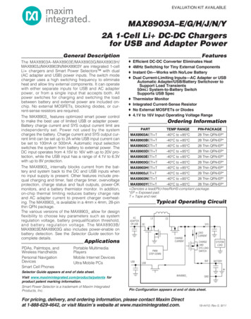
EVALUATION KIT AVAILABLEMAX8903A–E/G/H/J/N/Y2A 1-Cell Li DC-DC Chargersfor USB and Adapter PowerGeneral DescriptionThe 8903N/MAX8903Y are integrated 1-cellLi chargers and Smart Power Selectors with dual(AC adapter and USB) power inputs. The switch modecharger uses a high switching frequency to eliminateheat and allow tiny external components. It can operatewith either separate inputs for USB and AC adapterpower, or from a single input that accepts both. Allpower switches for charging and switching the loadbetween battery and external power are included onchip. No external MOSFETs, blocking diodes, or current-sense resistors are required.The MAX8903 features optimized smart power controlto make the best use of limited USB or adapter power.Battery charge current and SYS output current limit areindependently set. Power not used by the systemcharges the battery. Charge current and SYS output current limit can be set up to 2A while USB input current canbe set to 100mA or 500mA. Automatic input selectionswitches the system from battery to external power. TheDC input operates from 4.15V to 16V with up to 20V protection, while the USB input has a range of 4.1V to 6.3Vwith up to 8V protection.The MAX8903 internally blocks current from the battery and system back to the DC and USB inputs whenno input supply is present. Other features include prequal charging and timer, fast charge timer, overvoltageprotection, charge status and fault outputs, power-OKmonitors, and a battery thermistor monitor. In addition,on-chip thermal limiting reduces battery charge rateand AC adapter current to prevent charger overheating. The MAX8903 is available in a 4mm x 4mm, 28-pinthin QFN package.The various versions of the MAX8903 allow for designflexibility to choose key parameters such as systemregulation voltage, battery prequalification threshold,and battery regulation voltage. The MAX8903B/MAX8903E/MAX8903G also includes power-enable onbattery detection. See the Selector Guide section forcomplete details.FeaturesooooooooEfficient DC-DC Converter Eliminates Heat4MHz Switching for Tiny External ComponentsInstant On—Works with No/Low BatteryDual Current-Limiting Inputs—AC Adapter or USBAutomatic Adapter/USB/Battery Switchover toSupport Load Transients50mΩ System-to-Battery SwitchSupports USB SpecThermistor MonitorIntegrated Current-Sense ResistorNo External MOSFETs or Diodes4.1V to 16V Input Operating Voltage RangeOrdering InformationTEMP RANGEPIN-PACKAGEMAX8903AETI TPART-40 C to 85 C28 Thin QFN-EP*MAX8903BETI T-40 C to 85 C28 Thin QFN-EP*MAX8903CETI T-40 C to 85 C28 Thin QFN-EP*MAX8903DETI T-40 C to 85 C28 Thin QFN-EP*MAX8903EETI T-40 C to 85 C28 Thin QFN-EP*MAX8903GETI T-40 C to 85 C28 Thin QFN-EP*MAX8903HETI T-40 C to 85 C28 Thin QFN-EP*MAX8903JETI T-40 C to 85 C28 Thin QFN-EP*MAX8903NETI T-40 C to 85 C28 Thin QFN-EP*MAX8903YETI T-40 C to 85 C28 Thin QFN-EP* Denotes a lead(Pb)-free/RoHS-compliant package.*EP Exposed pad.T Tape and reel.Typical Operating CircuitACADAPTEROR USBLXSYSDCCHARGECURRENTApplicationsPDAs, Palmtops, andWireless HandheldsPersonal NavigationDevicesSmart Cell PhonesPortable MultimediaPlayersMobile Internet DevicesUltra Mobile PCsCSPWMSTEP-DOWNUSBLOADCURRENTCHARGEANDSYS LOADSWITCHBATUSBSYSTEMLOADBATTERYSelector Guide appears at end of data sheet.Visit www.maximintegrated.com/products/patents forproduct patent marking information.Smart Power Selector is a trademark of Maxim IntegratedProducts, Inc.MAX8903GNDPin Configuration appears at end of data sheet.For pricing, delivery, and ordering information, please contact Maxim Directat 1-888-629-4642, or visit Maxim’s website at www.maximintegrated.com.19-4410; Rev 5; 9/11
MAX8903A–E/G/H/J/N/Y2A 1-Cell Li DC-DC Chargersfor USB and Adapter PowerABSOLUTE MAXIMUM RATINGSDC, LX to GND .-0.3V to 20VDCM to GND .-0.3V to (VDC 0.3V)DC to SYS .-6V to 20VBST to GND .-0.3V to 26VBST TO LX .-0.3V to 6VUSB to GND .-0.3V to 9VUSB to SYS.-6V to 9VVL to GND .-0.3V to 6VTHM, IDC, ISET, CT to GND.-0.3V to (VVL 0.3V)DOK, FLT, CEN, UOK, CHG, USUS,BAT, SYS, IUSB, CS to GND .-0.3V to 6VSYS to BAT .-0.3V to 6VPG, EP (exposed pad) to GND .-0.3V to 0.3VDC Continuous Current (total in two pins).2.4ARMSUSB Continuous Current.1.6ALX Continuous Current (total in two pins).2.4ARMSCS Continuous Current (total in two pins) .2.4ARMSSYS Continuous Current (total in two pins) .3ARMSBAT Continuous Current (total in two pins) .3ARMSVL Short Circuit to GND .ContinuousContinuous Power Dissipation (TA 70 C)28-Pin Thin QFN-EPMultilayer (derate 28.6mW/ C above 70 C) .2286mW28-Pin Thin QFN-EPSingle-Layer (derate 20.8mW/ C above 70 C).1666.7mWOperating Temperature Range .-40 C to 85 CJunction Temperature Range .-40 C to 150 CStorage Temperature Range .-65 C to 150 CLead Temperature (soldering, 10s) . 300 CSoldering Temperature (reflow) . 260 CStresses beyond those listed under “Absolute Maximum Ratings” may cause permanent damage to the device. These are stress ratings only, and functionaloperation of the device at these or any other conditions beyond those indicated in the operational sections of the specifications is not implied. Exposure toabsolute maximum rating conditions for extended periods may affect device reliability.ELECTRICAL CHARACTERISTICS(VDC VUSB 5V, VBAT 4V, circuit of Figure 2, TA -40 C to 85 C, unless otherwise noted. Typical values are at TA 25 C.)(Note 4.14.4V16.51717.5VCharger enabled, no switching, VSYS 5V2.34Charger enabled, f 3MHz, VDC 5V15Charger enabled, VCEN 0V, 100mA USB mode (Note 2)12Charger enabled, VCEN 5V, 100mA USB mode (Note 2)VDCM 0V, VUSUS 5V10.1020.25DC INPUTDC Operating Range4.15No valid USB inputValid USB inputDC Undervoltage ThresholdWhen VDOK goes low, VDCrising, 500mV typical hysteresisDC Overvoltage ThresholdWhen VDOK goes high, VDC rising, 500mV typicalhysteresisDC Supply CurrentDC High-Side Resistance0.15ΩDC Low-Side Resistance0.15Ω0.31ΩDC-to-BAT Dropout ResistanceAssumes a 40mΩ inductor resistance (RL)DC-to-BAT Dropout VoltageWhen SYS regulation and charging stops, VDC falling,200mV hysteresis01530mVMinimum Off Time (tOFFMIN)100nsMinimum On Time (tONMIN)nsVDC 8V, VBAT 4V704MAX8903A/B/C/D/E/H/J/YSwitching Frequency (fSW)MAX8903GVDC 5V, VBAT 3V3VDC 9V, VBAT 4V1VDC 9V, VBAT 3V1DC Step-Down Output CurrentLimit Step RangeDC Step-Down Output CurrentLimit (ISDLIM)2mA0.5VDC 6V, VSYS 4VMHz2RIDC 3kΩ190020002100RIDC 6kΩRIDC 12kΩ95045010005001050550AmAMaxim Integrated
MAX8903A–E/G/H/J/N/Y2A 1-Cell Li DC-DC Chargersfor USB and Adapter PowerELECTRICAL CHARACTERISTICS (continued)(VDC VUSB 5V, VBAT 4V, circuit of Figure 2, TA -40 C to 85 C, unless otherwise noted. Typical values are at TA 25 C.)(Note 1)PARAMETERDC Soft-Start TimeDC Output Current500mA USB Mode (Note 3)DC Output Current100mA USB Mode (Note 2)SYS to DC Reverse CurrentBlockingCONDITIONSMINTYPMAXUNITSNo valid USB input1msValid USB input before soft-start20µsVDCM 0V, VIUSB 5V450475500mAVDCM 0V, VIUSB 0V9095100mAVSYS 5.5V, VDC 0V0.01µAUSB INPUTUSB Operating Range4.16.3USB Standoff VoltageV8VUSB Undervoltage ThresholdWhen VUOK goes low, VUSB rising, 500mV hysteresis3.954.04.05VUSB Overvoltage ThresholdWhen VUOK goes high, VUSB rising, 500mV hysteresis6.86.97.0VUSB Current LimitVIUSB 0V (100mA setting)9095100VIUSB 5V (500mA setting)4504755001.33ISYS IBAT 0mA, VCEN 0VUSB Supply CurrentISYS IBAT 0mA, VCEN 5VVUSUS 5V (USB suspend mode)Minimum USB to BAT Headroom0USB to SYS Dropout ResistanceUSB Soft-Start Time0.820.1150.2515300.20.35mAmAmVΩVUSB rising1msVDC falling below DC UVLO to initiate USB soft-start20µsSYS OUTPUTMinimum SYS Regulation Voltage(VSYSMIN)ISYS 1A,VBAT VSYSMINRegulation VoltageISYS Load RegulationISYS 0 to 2ACS to SYS ResistanceVDC 6V, VDCM 5V, VSYS 4V, ICS 1A0.07SYS to CS LeakageVSYS 5.5V, VDC VCS 0V0.01BAT to SYS ResistanceVDC VUSB 0V, VBAT 4.2V, ISYS 1A0.050.1ΩBAT to SYS Reverse RegulationVoltageVUSB 5V, VDC 0V, VIUSB 0V, ISYS 200mA5075100mVSYS Undervoltage ThresholdSYS falling, 200mV hysteresis (Note 4)1.81.92.0VMaxim IntegratedmV/AΩµA3
MAX8903A–E/G/H/J/N/Y2A 1-Cell Li DC-DC Chargersfor USB and Adapter PowerELECTRICAL CHARACTERISTICS (continued)(VDC VUSB 5V, VBAT 4V, circuit of Figure 2, TA -40 C to 85 C, unless otherwise noted. Typical values are at TA 25 C.)(Note 1)PARAMETERCONDITIONSMINTYPMAXTA 25 C4.1794.2004.221UNITSBATTERY CHARGERMAX8903A/B/C/G/HMAX8903D/EBAT Regulation Voltage(VBATREG)IBAT 0mAMAX8903JBAT Prequal Threshold (VBATPQ)Prequal Charge CurrentFast-Charge CurrentDONE Threshold (ITERM)4.1584.2004.2424.0794.1004.121TA -40 C to 85 C4.0594.1004.141TA 25 C4.3284.3504.372TA -40 C to 85 C4.3074.3504.394TA 25 C4.1294.1504.171TA -40 C to 85 3.03.1MAX8903B/E/G2.42.52.6RISET 600Ω180020002200RISET 1.2kΩ (MAX8903A/C/D)90010001100RISET 2.4kΩ450500550MAX8903Y/NCharger Restart ThresholdTA -40 C to 85 CTA 25 CChange in VBAT from DONE to fast-chargeVBAT rising 180mVhystersisPercentage of fast-charge current set at ISET10Percentage of fast-charge, IBAT decreasingRISET Resistor RangemVV%100.6VmA%2.4kΩISET Output Voltage1.5VISET Current Monitor Gain1.25mA/ABAT Leakage CurrentNo DC or USB inputWith valid input power, VCEN 5V0.05436µACharger Soft-Start Time1.0msCharger Thermal LimitTemperature100 C5%/ CCharger Thermal Limit GainCharge current 0 at 120 CCHARGER TIMERPrequalification TimeCCT 0.15µF33minFast-Charge TimeCCT 0.15µF660minMAX8903A/C/D/H/J/N/Y (fixed)15sTop-Off Timer (tTOP-OFF)MAX8903B/E/G, CCT 0.15µFTimer Accuracy132-15min 15%Timer Extend Current ThresholdPercentage of fast-charge current below which the timerclock operates at half-speed405060%Timer Suspend Current ThresholdPercentage of fast-charge current below which timerclock pauses162024%4Maxim Integrated
MAX8903A–E/G/H/J/N/Y2A 1-Cell Li DC-DC Chargersfor USB and Adapter PowerELECTRICAL CHARACTERISTICS (continued)(VDC VUSB 5V, VBAT 4V, circuit of Figure 2, TA -40 C to 85 C, unless otherwise noted. Typical values are at TA 25 C.)(Note 1)PARAMETERCONDITIONSMINTYPMAXUNITSTHERMISTOR MONITORTHM Threshold, HotWhen charging is suspended, 1% hysteresis0.27 xVVL0.28 xVVL0.29 xVVLVTHM Threshold, ColdWhen charging is suspended, 1% hysteresis0.73 xVVL0.74 xVVL0.75 xVVLVTHM Threshold, DisabledTHM function is disabled below this voltage0.0254x VVL0.03 xVVL0.036 xVVLVTHM Threshold DC, USB EnableMAX8903B/MAX8903E/MAX8903G0.83 xVVL0.87 xVVL0.91 xVVLV-0.100 0.001 0.200MAX8903A/C/D/H/J/N/YTHM GND or VL;TA 25 CTHM GND or VL;TA 85 CTHM Input LeakageMAX8903B/E/GTHM GND or VL;TA -40 C to 85 CµA 0.010-0.200 0.001 0.200THERMAL SHUTDOWN, VL, AND LOGIC I/O: CHG, FLT, DOK, UOK, DCM, CEN, USUS, IUSBHigh levelLogic-Input Thresholds(DCM, CEN, USUS, IUSB)Logic-Input Leakage Current(CEN, USUS, IUSB)1.3Low level0.4HysteresisVINPUT 0V to 5.5V(MAX8903A/C/D/H/J/N/Y)VINPUT 0V to 5.5V(MAX8903B/E/G)50TA 25 C-1.000TA 85 CTA -40 C to 85 C 0.001 0.200TA 25 C0.0011TA 85 C0.01VDCM 0V to 16VVDC 16VLogic Output Voltage, Low(CHG, FLT, DOK, UOK)Sinking 1mA8Sinking 10mA80Maxim IntegratedµA 0.001Logic-Input Leakage Current(DCM)Open-Drain Output LeakageVOUT 5.5VCurrent, High (CHG, FLT, DOK, UOK)mV 1.000 0.010-0.200TA 25 C0.001TA 85 C0.01V501µAmVµA5
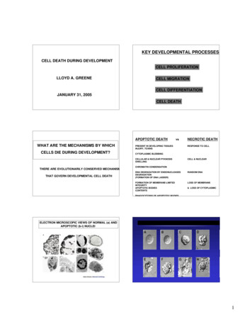
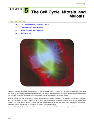
ELECTRICAL CHARACTERISTICS (continued)(VDC VUSB 5V, VBAT 4V, circuit of Figure 2, TA -40 C to 85 C, unless otherwise noted. Typical values are at TA 25 C.)(Note 1)PARAMETERCONDITIONSVL Output VoltageMINTYPMAXIVL 0 to 1mA(MAX8903A/C/D/H/J/N/Y)4.65.05.4IVL 0 to 10mA(MAX8903B/E/G)4.65.05.4UNITSVVDC VUSB 6VVL UVLO Threshold3.2VThermal Shutdown Temperature160 CThermal Shutdown Hysteresis15 CVVL falling; 200mV hysteresisNote 1: Limits are 100% production tested at TA 25 C. Limits over the operating temperature range are guaranteed by design.Note 2: For the 100mA USB mode using the DC input, the step-down regulator is turned off and its high-side switch operates as alinear regulator with a 100mA current limit. The linear regulator’s output is connected to LX and its output current flowsthrough the inductor into CS and finally to SYS.Note 3: For the 500mA USB mode, the actual current drawn from USB is less than the output current due to the input/output currentratio of the DC-DC converter.Note 4: For short-circuit protection, SYS sources 25mA below VSYS 400mV, and 50mA for VSYS between 400mV and 2V.Typical Operating Characteristics(TA 25 C, unless otherwise noted.)MAX8903A/B/C/D/E/H/J/N/YBATTERY CHARGER EFFICIENCYvs. BATTERY VOLTAGEEFFICIENCY (%)VDC 8V6050VDC 12V403070VDC 9V6050VDC 12V4030IBAT 0.15A20IBAT 1.5AIBATT 0.15A2010IBATT 1.5A1.52.02.53.03.54.0BATTERY VOLTAGE (V)4.55.03.5VBAT 3V3.02.5VBAT 4V2.01.51.0RISET 1.2kΩVCEN 0V0.001.04.00.51006VDC 6V804.5MAX8903A toc02VDC 5V7090SWITCHING FREQUENCY (MHz)80100MAX8903A toc01a90MAX8903A/B/C/D/E/H/J/N/YSWITCHING FREQUENCY vs. VDCMAX8903G BATTERY CHARGEREFFICIENCY vs. BATTERY VOLTAGEMAX8903A toc01100EFFICIENCY (%)MAX8903A–E/G/H/J/N/YMAX8903A–E/G/H/J/N/Y2A 1-Cell Li DC-DC Chargersfor USB and Adapter Power1.01.52.02.53.03.54.0BATTERY VOLTAGE (V)4.55.046810121416DC VOLTAGE (V)Maxim Integrated
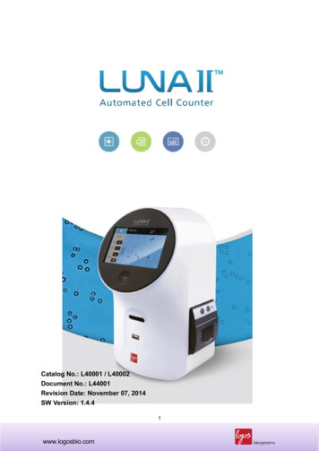
MAX8903A–E/G/H/J/N/Y2A 1-Cell Li DC-DC Chargersfor USB and Adapter PowerTypical Operating Characteristics (continued)(TA 25 C, unless otherwise noted.)MAX8903A/B/C/D/E/H/J/N/YSYS EFFICIENCYvs. SYS OUTPUT CURRENTVBAT 4VVBAT 3V0.4VDC 11V50VDC 16V4030VDC 6V20RISET 1.2kIVCEN 0V0.21068101214VDC 12V40VDC 9V30VDC 6V1010100100001000110100SYS OUTPUT CURRENT (mA)USB SUPPLY CURRENTvs. USB VOLTAGEUSB SUPPLY CURRENTvs. USB VOLTAGE (SUSPEND)BATTERY LEAKAGE CURRENTvs. BATTERY VOLTAGE0.6CHARGERDISABLED0.412010080604080BATTERY LEAKAGE CURRENT (nA)0.8140MAX8903A toc05MAX8903A toc041.0200.270605040302010NO DC OR USB INPUTUSB SUSPEND012345670123456072345USB VOLTAGE (V)BATTERY VOLTAGE (V)BATTERY LEAKAGE CURRENTvs. AMBIENT TEMPERATURECHARGE CURRENTvs. BATTERY VOLTAGE—USB MODECHARGE CURRENTvs. BATTERY VOLTAGE—DC MODE6050403020350300VIUSB VUSB250200VIUSB 0V15010010NO DC OR USB INPUT-151035TEMPERATURE ( C)Maxim Integrated6085800MAX8903A toc096CHARGER ENABLEDIBAT SET TO 1AIDC SET TO 2AMAX8903A/C/HVBAT RISING60040020050001000CHARGE CURRENT (mA)400CHARGE CURRENT (mA)70CHARGE ENABLEDIBAT SET TO 1.5AMAX8903DVBAT RISING4501200MAX8903A toc08500MAX8903A toc0780-401USB VOLTAGE (V)90BATTERY LEAKAGE CURRENT (nA)00010,0001000SYS OUTPUT CURRENT (mA)CHARGERENABLED1.2VDC 16V50DC VOLTAGE (V)1.61.4600116USB QUIESCENT CURRENT (µA)47020VDC 4.5V00USB SUPPLY CURRENT (mA)6080MAX8903A toc060.670VCEN 190SYS EFFICIENCY (%)1.00.880SYS EFFICIENCY (%)1.2VCEN 1VVSYS 4.4V90100MAX8903A toc031.4SWITCHING FREQUENCY (MHz)100MAX8903A toc02a1.6MAX8903G SYS EFFICIENCYvs. SYS OUTPUT CURRENTMAX8903A toc03aMAX8903G SWITCHINGFREQUENCY vs. VDC01.52.02.53.03.5BATTERY VOLTAGE (V)4.04.51.52.02.53.03.54.04.5BATTERY VOLTAGE (V)7
MAX8903A–E/G/H/J/N/Y2A 1-Cell Li DC-DC Chargersfor USB and Adapter PowerTypical Operating Characteristics (continued)(TA 25 C, unless otherwise noted.)NORMALIZED BATTERYREGULATION VOLTAGEvs. AMBIENT 0.34.0100.1100.099.92.099.71.00.522ppm/ C103508560RSYS 1MΩ099.5-15VUSB RISING1234567USB VOLTAGE (V)MAX8903A/C/D/H/N/YSYS VOLTAGE vs. DC VOLTAGESYS VOLTAGEvs. SYS OUTPUT CURRENT, DC INPUTSYS VOLTAGEvs. SYS OUTPUT CURRENT, USB INPUTVDC FALLING1.54.3MAX8903A/C/D/H, MAX8903N/Y,VDC 5.75VVDC 5.75VMAX8903B/E/G,VDC 5.75V4.14.01.0VCEN 5VVBAT 0VVUSB 0V0.524681012141600.51.01.5MAX8903 , VUSB 0V3.82.01000VL WITHNO LOAD ANDDCDC OFF(VUSUS 5V)VL AND DCDCWITHFULL LOAD(VUSUS 0V)21VBAT 3.6VVUSB 0V0VBAT (V)5MAX8903A toc176.05.55.04.54.03.53.0IDC SET TO 1AIBAT SET TO 2AVBAT246810 12 14 16 18 20DC VOLTAGE 903A/B/C/G/H00300CHARGE PROFILE—1400mAh BATTERYADAPTER INPUT—1A CHARGEMAX8903A toc166200SYS OUTPUT CURRENT (mA)VL VOLTAGE vs. DC VOLTAGE3MAX8903B/E/G,VUSB 5V4.1SYS OUTPUT CURRENT (A)DC VOLTAGE (V)4MAX8903A /C/D/H, MAX8903N/Y,VUSB 5VVUSB 5V4.23.9MAX8903 , VDC 0V3.8184.34.03.90MAX8903J, VUSB 5V4.44.2MAX8903A toc15VDC 0V, VBATT 4V4.5IBAT (A)2.04.6SYS VOLTAGE (V)2.5MAX8903J, VDC 5.75V4.4SYS VOLTAGE (V)VDC RISING3.0VUSB 0V4.5MAX8903A toc144.6MAX8903A toc133.5VL VOLTAGE (V)2.51.5-40VUSB FALLING3.0TEMPERATURE ( C)4.003.599.899.6VCEN 5VVBAT 0VVDC 0V4.5100.2854.585.0MAX8903A toc12100.4TEMPERATURE ( C)5.0SYS VOLTAGE (V)100.5SYS VOLTAGE (V)1.010MAX8903A/C/D/H/N/YSYS VOLTAGE vs. USB VOLTAGEMAX8903A toc11VUSB 5V, VBAT 4VNORMALIZED BATTERY REGULATION VOLTAGE (%)NORMALIZED CHARGE CURRENT1.015MAX8903A toc10NORMALIZED CHARGE CURRENTvs. AMBIENT TEMPERATURE0204060801000.0120 140TIME (min)Maxim Integrated
MAX8903A–E/G/H/J/N/Y2A 1-Cell Li DC-DC Chargersfor USB and Adapter PowerTypical Operating Characteristics (continued)(TA 25 C, unless otherwise noted.)MAX8903A/B/C/G/HCHARGE PROFILE—1400mAh BATTERYUSB INPUT—500mA CHARGEMAX8903A toc185.0MAX8903A MAX8903B/MAX8903CIUSB SET TO 500mAIBAT SET TO 2A0.500IBAT (A)VBAT (V)MAX8903A/B/C/D/E/H/J/N/Y DC SWITCHINGWAVEFORMS—LIGHT LOAD0.105V/divVLX0VILX0.05RSYS 44Ω020 40 60 80 100 120 140 160 180 200500mA/div0A200ns/divTIME (min)MAX8903A/B/C/D/E/H/J/N/Y DC SWITCHINGWAVEFORMS—HEAVY LOADMAX8903G DC SWITCHINGWAVEFORMS—LIGHT LOADMAX8903A toc20MAX8903A toc19a50mV/divAC-COUPLEDVSYSVDC 9V, L 2.2µHCSYS 22µF,RSYS /divILX0AILX500mA/divRSYS 5Ω0A1µs/div200ns/divMAX8903G DC SWITCHINGWAVEFORMS—HEAVY LOADDC CONNECT WITHUSB CONNECTED (RSYS 25Ω)MAX8903A toc21MAX8903A toc20a3.6VVSYSVDC 9V, L 2.2µHCSYS 22µF, RSYS 5ICEN 7mA475mA500mA/div500mA/div-IBAT xim Integrated200µs/div9
MAX8903A–E/G/H/J/N/Y2A 1-Cell Li DC-DC Chargersfor USB and Adapter PowerTypical Operating Characteristics (continued)(TA 25 C, unless otherwise noted.)DC CONNECT WITH NO USB(RSYS 25Ω)DC DISCONNECT WITH NO USB(RSYS 25Ω)MAX8903A CHARGINGIDCMAX8903A toc23CSYSCHARGING 850mA3.68V3.6VVSYS3.6VVBAT5V/div1A/divIDC0A-IBAT CHARGINGIBAT144mA 8903B/E SYS LOAD TRANSIENTMAX8903A toc24aMAX8903A toc24b4.400VMAX8903AVDC 10.5VL 2.2µHCSYS 10µFRIDC 3kI (2A)DCM HIGHCEN 120mV/divAC-COUPLED4.360V4.325VVSYSMAX8903BVDC 10.5VL 2.2µHCSYS 22µFRIDC 3kI (2A)DCM HIGHCEN 1 0µs/div100µs/divMAX8903G SYS LOAD TRANSIENTUSB CONNECT WITH NO DC(RSYS 25Ω)MAX8903A toc25MAX8903A toc24c3.6VVSYS4.325VVSYS4.305V1AISYS50mV/divVDC 9VL 2.2µHCSYS 22µFRIDC 3kI (2A)DCM 1CEN 10A100µs/div101A/div-IBAT CHARGING-1AMAX8903A/C/D/H SYS LOAD mA/div-330mA400µs/divMaxim Integrated
MAX8903A–E/G/H/J/N/Y2A 1-Cell Li DC-DC Chargersfor USB and Adapter PowerTypical Operating Characteristics (continued)(TA 25 C, unless otherwise noted.)USB DISCONNECT WITH NO DC(RSYS 25Ω)USB SUSPENDMAX8903A toc26VSYS3.6VVUSB2V/div5V/div5VUSB RESUMEMAX8903A toc27VUSUSIUSB0V475mA3VMAX8903A toc285V/div0AVUSUS500mA/divIUSB0V3V500mA/div VSYSIBAT-330mA144mA100µs/div2V/div3.7V500mA/div IBAT TTERYCHARGERSOFT-START-475mA500mA/div200µs/divPin DescriptionPINNAME1, 2PGFUNCTIONPower Ground for Step-Down Low-Side Synchronous n-Channel MOSFET. Both PG pins must beconnected together externally.DC Power Input. DC is capable of delivering up to 2A to SYS. DC supports both AC adapter and USBinputs. The DC current limit is set through DCM, IUSB, or IDC depending on the input source used. SeeTable 2. Both DC pins must be connected together externally. Connect at least a 4.7µF ceramic capacitorfrom DC to PG.Current-Limit Mode Setting for the DC Power Input. When logic-high, the DC input current limit is set bythe resistance from IDC to GND. When logic-low, the DC input current limit is internally programmed to500mA or 100mA, as set by the IUSB logic input. There is an internal diode from DCM (anode) to DC(cathode) as shown in Figure 1.3, 4DC5DCM6BSTHigh-Side MOSFET Driver Supply. Bypass BST to LX with a 0.1µF ceramic capacitor.7IUSBUSB Current-Limit Set Input. Drive IUSB logic-low to set the USB current limit to 100mA. Drive IUSB logichigh to set the USB current limit to 500mA.8DOKDC Power-OK Output. Active-low open-drain output pulls low when a valid input is detected at DC. DOKis still valid when the charger is disabled (CEN high).9VLLogic LDO Output. VL is the output of an LDO that powers the MAX8903 internal circuitry and chargesthe BST capacitor. Connect a 1µF ceramic capacitor from VL to GND.10CTCharge Timer Set Input. A capacitor (CCT) from CT to GND sets the fast-charge and prequal fault timers.Connect to GND to disable the timer.11IDCDC Current-Limit Set Input. Connect a resistor (RIDC) from IDC to GND to program the current limit of thestep-down regulator from 0.5A to 2A when DCM is logic-high.12GNDGround. GND is the low-noise ground connection for the internal circuitry.Maxim Integrated11
MAX8903A–E/G/H/J/N/Y2A 1-Cell Li DC-DC Chargersfor USB and Adapter PowerPin Description (continued)PINNAME13ISETCharge Current Set Input. A resistor (RISET) from ISET to GND programs the fast-charge current up to 2A.The prequal charge current is 10% of the fast-charge current.14CENCharger Enable Input. Connect CEN to GND to enable battery charging when a valid source is connectedat DC or USB. Connect to VL, or drive high to disable battery charging.15USUSUSB Suspend Input. Drive USUS logic-high to enter USB suspend mode, lowering USB current to 115µA,and internally shorting SYS to BAT.16THMThermistor Input. Connect a negative temperature coefficient (NTC) thermistor from THM to GND.Connect a resistor equal to the thermistor 25 C resistance from THM to VL. Charging is suspendedwhen the thermistor is outside the hot and cold limits. Connect THM to GND to disable the thermistortemperature sensor.17USBUSB Power Input. USB is capable of delivering 100mA or 500mA to SYS as set by the IUSB logic input.Connect a 4.7µF ceramic capacitor from USB to GND.18FLTFault Output. Active-low, open-drain output pulls low when the battery timer expires before prequal orfast-charge completes.19UOKUSB Power-OK Output. Active-low, open-drain output pulls low when a valid input is detected at USB.UOK is still valid when the charger is disabled (CEN high).20, 21BATBattery Connection. Connect to a single-cell Li battery. The battery charges from SYS when a validsource is present at DC or USB. BAT powers SYS when neither DC nor USB power is present, or when theSYS load exceeds the input current limit. Both BAT pins must be connected together externally.22CHGCharger Status Output. Active-low, open-drain output pulls low when the battery is in fast-charge orprequal. Otherwise, CHG is high impedance.23, 24SYSSystem Supply Output. SYS connects to BAT through an internal 50mΩ system load switch when DC orUSB are invalid, or when the SYS load is greater than the input current limit.When a valid voltage is present at DC or USB, SYS is limited to VSYSREG. When the system load (ISYS)exceeds the DC or USB current limit, SYS is regulated to 50mV below BAT, and both the powered inputand the battery service SYS.Bypass SYS to GND with an X5R or X7R ceramic capacitor. See Table 6 for the minimum recommendedSYS capacitor (CSYS). Both SYS pins must be connected together externally.25, 26CS70mΩ Current-Sense Input. Connect the step-down inductor from LX to CS. When the step-downregulator is on, there is a 70mΩ current-sense MOSFET from CS to SYS. When the step-down regulator isoff, the internal CS MOSFET turns off to block current from SYS back to DC.27, 28LXInductor Connection. Connect the inductor between LX and CS. Both LX pins must be connected togetherexternally.—EPExposed Pad. Connect the exposed pad to GND. Connecting the exposed pad does not remove therequirement for proper ground connections to the appropriate pins.12FUNCTIONMaxim Integrated
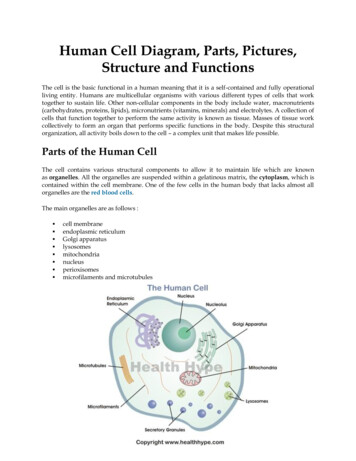
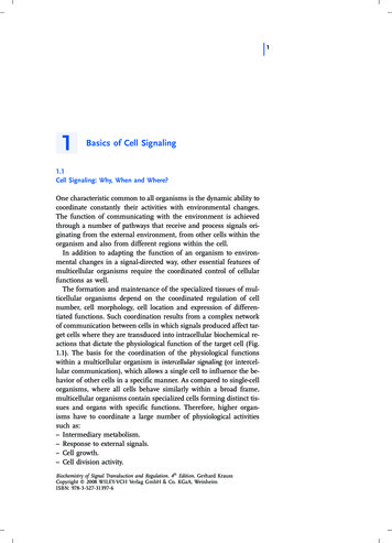
MAX8903A–E/G/H/J/N/Y2A 1-Cell Li DC-DC Chargersfor USB and Adapter PowerPGACADAPTERDCLXBSTCSMAX8903DC POWERMANAGEMENTSYSPWROKLi BATTERYCHARGERAND SYS LOAD TORBATBAT BAT-USB POWERMANAGEMENTUSBUSBPWROKTTHERMISTORMONITOR(SEE FIGURE TIONNTCVLCHARGETERMINATIONAND MONITORSETINPUTLIMITTHMCHGDCDCMFLTDC RINPUT ANDCHARGERCURRENT-LIMITSET LOGICCENIDCDCLIMITCTGNDEPFigure 1. Functional Block DiagramMaxim Integrated13
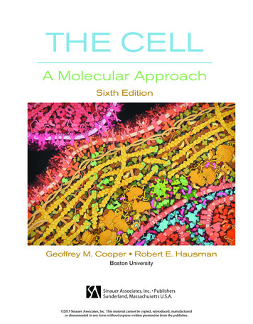
MAX8903A–E/G/H/J/N/Y2A 1-Cell Li DC-DC Chargersfor USB and Adapter PowerRPU4 x 100kΩTO VL12PGPGMAX8903CDC4.7µFUOK3 DCADAPTERDOK4 DC6CBST0.1µFFLTCHGBST27 LX18FAULTOUTPUT19USB PWR OK8DC PWR OK22CHARGEINDICATOR13RISET11RIDCISET28 LXIDCL11µH25CS(SEE TABLE 5 FORINDUCTOR SELECTION)26CSSYS24SYS23BAT21BAT20TO SYSTEMLOADCSYS(SEE TABLE 6 FOR CSYS SELECTION)USB17VBUSUSBCUSB4.7µFGNDTO DC5OFFCHARGE ON14500mA100mA7USB SUSPEND1510CCT0.15µFCBAT10µF1-CELLLI D12EPFigure 2. Typical Application Circuit Using a Separate DC and USB ConnectorCircuit DescriptionThe MAX8903 is a dual input charger with a 16V inputfor a wide range of DC sources and USB inputs. The ICincludes a high-voltage (16V) input DC-DC step-downconverter that reduces charger power dissipation whilealso supplying power to the system load. The stepdown converter supplies up to 2A to the system, thebattery, or a combination of both.14A USB charge input can charge the battery and powerthe system from a USB power source. When poweredfrom USB or the DC input, system load current peaksthat exceed what can be supplied by the input are supplemented by the battery.The MAX8903 also manages load switching from thebattery to and from an external power source with anon-chip 50mΩ MOSFET. This switch also helps supportload peaks using battery power when the input sourceis overloaded.Maxim Integrated
MAX8903A–E/G/H/J/N/Y2A 1-Cell Li DC-DC Chargersfor USB and Adapter PowerRPU4 x 100kΩTO VL12PGPGMAX8903CDC4.7µFDOK4 DCD-6D CBST0.1µFIDGNDCHGBST27 LX18FAULTOUTPUT19USB PWR-OK8DC PWR-OK22CHARGEINDICATOR13RISET11RIDCISET28 LXL11µH499kΩIDC25CS26CS(SEE TABLE 5 FORINDUCTOR VALUESELECTION)17DC MODEUOK3 DCVBUSFLTUSBADAPTER5OFFCHARGE ON14500mA100mA7USB SUSPEND1510CCT0.15µFUSBSYS24SYS23BAT21BAT20TO SYSTEMLOADCSYS(SEE TABLE 6 FOR CSYS SELECTION)CBAT10µF1-CELLLI D12EPFigure 3. Typical Application Circuit Using a Mini 5 Style Connector or Other DC/USB Common ConnectorAs shown in Figure 1, the IC includes a full-featuredcharger with thermistor monitor, fault timer, chargerstatus, and fault outputs. Also included are power-OKsignals for both USB and DC. Flexibility is maintainedwith adjustable charge current, input current limit, anda minimum system voltage (when charging is scaledback to hold the system voltage up).The MAX8903 prevents overheating during high ambient temperatures by limiting charging current when thedie temperature exceeds 100 C.Maxim IntegratedDC Input—Fast HystereticStep-Down RegulatorIf a valid DC input is present, the USB power path isturned off and power for SYS and battery charging issupplied by the high-frequency step-down regulatorfrom DC. If the battery voltage is above the minimumsystem voltage (VSYSMIN, Figure 4), the battery chargerconnects the system voltage to the battery for lowestpower dissipation. The step-down regulation point isthen controlled by three feedback signals: maximumstep-down output current programmed at IDC, maximumcharger current programmed at ISET, and maximum15
MAX8903A–E/G/H/J/N/Y2A 1-Cell Li DC-DC Chargersfor USB and Adapter PowerTable 1. External Components List for Figures 2 and 3COMPONENT(FIGURES 2 AND 3)CDC, CUSBFUNCTIONInput filter capacitor4.7µF ceramic capacitorCVLVL filter capacitor1.0µF ceramic capacitorCSYSSYS output bypass capacitor10µF (MAX8903A/MAX8903C/MAX8903D/MAX8903H/MAX8903J) or22µF (MAX8903B/MAX8903E/MAX8903G/MAX8903Y) ceramic capacitorCBATBattery bypass capacitor10µF ceramic capacitorCCTCharger timing
19-4410; Rev 5; 9/11 For pricing, delivery, and ordering information, please contact Maxim Direct at 1-888-629-4642, or visit Maxim's website at www.maximintegrated.com.