Transcription
USBtinyISPCreated by lady adahttps://learn.adafruit.com/usbtinyispLast updated on 2021-11-15 05:59:25 PM EST Adafruit IndustriesPage 1 of 94
Table of ContentsOverview5 5566667AVR programmer & SPI interfaceIntroductionWhat's so great about it?Easy to makeEasy to useEasy to powerEasy to extendF.A.Q.7Make It!9 Make Make Make Step-by-step99Preparation9 Get ready to solder, sports-racers! Tutorials Tools9910Parts list13 Kit parts list Schematic (v2.0)1323Solder it! Ouch, hot! Make 6-pin cable (Old kits, without pre-made 6-pin cables) CaseParts (v1.0)2424384143 Kit parts list43 This is the list for very old kits, its very unlikely you have a v1.0 but we're keeping it around for historical record43Solder (v1.0) V1.0 instructions!Its very unlikely you have a v1.0 but we're keeping it around for historical recordSolder it!Make 6-pin cableCaseUse It! How to use it!Indicator LEDsProgramming CablesJumper JP3 (USB power to target)Using it as an SPI interfaceUser Manual How to use it! Indicator LEDs Programming Cables Adafruit Industries52525252636667676768686869696970Page 2 of 94
Jumper JP3 (USB power to target) Using it as an SPI interface7070Drivers71 AVR programmer & SPI interface Windows 7, 8 & XP Mac OS X & Linux717174AVRDUDE Using the programmer with AVRDUDEFor WindowsFor Mac OS XFor LinuxAVRStudio AVRISP/STK500v2 compatibility bridgeNotesStep 1. COM bridgeStep 2. Install AVRStudioStep 3. Download USBtiny500Download Windows DriversAVRDUDEHardware/Firmware Files for v2.0Hardware/Firmware Files for v1.0USBtiny500 compatibility bridge for AVR StudioHELP!!! Frequently Asked QuestionsI'm running avrdude and I get "Initialization failed, rc 1"Check:It doesn't work with a USB 3 portI'm running avrdude and I get "error: usbtiny transmit: initialization failed, rc -1"It's not working!I'm running avrdude and I get "USB read error: expected 4, got -1" (or something similar)My 64 bit computer doesn't seem to work!I'm having trouble compiling/burning the chip for this project.I'm running avrdude and I get "Could not find USB device 0x1781/0xc9f"I'm having trouble building this project from scratch.I'm running avrdude and I get "error at avrdude.conf:370 unrecognized character: 'u'"I'm running avrdude and I get 'avrdude: Can't find programmer id "usbtiny" Adafruit 9091919292929393949494Page 3 of 94
Adafruit IndustriesPage 4 of 94
OverviewAVR programmer & SPI interfaceIntroductionThis is documentation for a simple open-source USB AVR programmer and SPIinterface. It is low cost (https://adafru.it/cf1), easy to make (https://adafru.it/cf2), worksgreat with avrdude (https://adafru.it/cf3), is AVRStudio-compatible (https://adafru.it/cf4)and tested under Windows, Linux and MacOS X. Perfect for students and beginners,or as a backup programmer.The project is based off of the USBtiny code & design (https://adafru.it/cf5). The mainimprovements are: adjusting the code to allow it to act as a SpokePOV (https://adafru.it/cf6) interface, adding lowlevel bitbang commands, and addition of a "USBgood" LED. Other changes are new VID/PID (to make it official), removing some of thecommands, and moving around the pins a bit.You can build this design using the schematic and firmware (https://adafru.it/cf7), orbuy a kit from the Adafruit webshop (https://adafru.it/aK1). Having a full kit availablesolves the "chicken & egg" problem of purchasing or building a USB programmer thatthen needs a programmer of some sort to 'kick start'. (See USBasp (https://adafru.it/aNU), AVRdoper (https://adafru.it/cf8), USBprog (https://adafru.it/cf9)) Adafruit IndustriesPage 5 of 94
All the firmware code is distributed under the GPL, the hardware design layout filesare CC 2.5 Attrib./Share-alike (https://adafru.it/c37).What's so great about it?Easy to make Ultra low cost: programmer is 16 in parts, less than half the price of the AVRISPv2 ! (Kits are 22 and available from the adafruit shop (https://adafru.it/aK1).) Kit comes with both 6-pin and 10-pin AVR-standard connectors and cables.Almost no programmers that are not from Atmel have both! (Including theAVRISP v2) Easy to build: All through-hole parts, all common and available from largedistributors.Easy to use AVRdude compatible - support for usbtiny added in v5.5! (https://adafru.it/cf3) USB drivers available for Windows (https://adafru.it/cf7) using libusb, no driversneeded for Mac OS X or Linux. Durable off-the-shelf enclosure High speed! Max clock rate is 400KHz. Write speed:1Kb/s, read speed: 2Kb/s.(Atmega8 takes 8s to write, 4s to read/verify) 2 LEDs to indicate "USB/Power good" and "Busy" I/O is buffered to allow programming of 2V-6V targets (v2) Works with any AVR ISP chip with 64K of flash (or less) - does not work withAtmega1281/1280/2561/2560Easy to power Powered off of 5V USB bus at less than 100mA to allow it to be used withunpowered USB hubs Easily accessable jumper to power target project off of USB (target must be 5Vtolerant, of course) Remove the jumper and it will self-power but buffer the I/O to match the targetdevice. (v2) Adafruit IndustriesPage 6 of 94
Easy to extend Easily interfaced with libusb Existing firmware allows for fast SPI interfacing using USB Bit-bang commands provide 8 bits of I/O control (including LED) for open-endedproject ideasF.A.Q.Is this sold as an assembled programmer?Not yet, it is only available as a kit.How hard is it to assemble?There are very clear instructions availble in the "Make it! (https://adafru.it/cf2)" link.It's a simple kit and should be fairly easy for anyone with proper tools even if it'stheir first soldering project.Does this work with linux?Yes. We have tested it with linux (Ubuntu 7.04) and it didn't require anythingstrange so it should work with any distribution. If you're having problems makesure you are running as root to have permissions on the device.Why is there no Serial/COM/port (or /dev/ttyXX device) ?USBtiny is not a USB-Serial device, it is its own USB protocol which is understoodby Avrdude. You will not see a COM port or Serial port created when you plug it in.Can I send serial messages using the USBtiny as well asprogramming, like an Arduino?No, the USBtiny does not create a serial port and cannot do that. It programs chipsdirectly, using the ISP connection, not Serial. Arduinos are not AVR programmers,they are an AVR with a bootloader that runs over a serial port.What chips can be programmed? Adafruit IndustriesPage 7 of 94
Any AVR that uses the ISP interface for programming and has 64K or less of flashcan be programmed.Chips such as the Atmega1280/1281 and Atmega2560/2561 have more than 64Kand cannot be programmed.Chips that use TPI interface, such as Attiny4/5/9/10 cannot be programmed.Some very old chips such as the AT90S1200 and similar cannot be programmedCan I program a bootloader (like an Arduino one) withUSBtinyISP?Yes, this is what an AVR programmer can do. We suggest using the 'built in'bootloader-burner in the IDE to do it.How do I program a bootloader onto an Arduino?1. Put a fresh AVR chip (such as an Atmega328) into the Arduino in the correctorientation2. Remove the jumper from the USBtinyISP3. Plug in the USBtiny to USB4. Plug the Arduino into DC or USB so it is powered5. Plug the 6 pin cable from the USBtinyISP into the Arduino so that pin 1 mark islined up with the red wire on the cable6. Start up Arduino IDE7. Select the chip/Arduino you are using in the Tools- Board menu8. Do not select a COM/Serial port9. Select Tools- Burn Bootloader- w/USBtinyISP10. The USBtinyISP red LED should light up. It will take a minute or two toprogram the chip11. When it is done, the IDE will tell you it has completed and the red LED will beoff.I need help getting this workingCheck the HELP! page (https://adafru.it/cfa). Adafruit IndustriesPage 8 of 94
Does this work with the 8051-core (AT89) series chips?The USBtinyISP design as-is only works with the AVR core chips (ATtiny/ATmega/etc). However Lucas Chiesa and his peers have done an excellent job porting thisversion to support 8051-core chips. (https://adafru.it/uGa)What is "Self Program"?The original USBtinyISP could be programmed by another programmer byjumpering a pin. This is not true anymore now that there is a buffer. You shouldignore the jumper.Also, you cannot program the usbtiny with itself.Make It!Make Make MakeStep-by-stepMaking a USBtinyISP from kit is easy, just follow these steps:1. Preparation and tutorials (https://adafru.it/cfd)2. Parts list check (https://adafru.it/cf1) (v2.0) or if you have an older version, partslist for v1.0 (https://adafru.it/cfe)3. Solder it together! (https://adafru.it/cf2) (v2.0) or if you have an older version, assembly for v1.0 (https://adafru.it/cff)PreparationGet ready to solder, sports-racers!TutorialsLearn how to solder with tons of tutorials! (https://adafru.it/aTk)Don't forget to learn how to use your multimeter too! (https://adafru.it/aZZ) Adafruit IndustriesPage 9 of 94
ToolsThere are a few tools that are required for assembly. None of these tools areincluded. If you don't have them, now would be a good time to borrow or purchasethem. They are very very handy whenever assembling/fixing/modifying electronicdevices! I provide links to buy them, but of course, you should get them whereever ismost convenient/inexpensive. Many of these parts are available in a place like RadioShack or other (higher quality) DIY electronics stores.Soldering ironAny entry level 'all-in-one' soldering ironthat you might find at your local hardwarestore should work. As with most things inlife, you get what you pay for.Upgrading to a higher end soldering ironsetup, like the Hakko FX-888 that westock in our store (http://adafru.it/180),will make soldering fun and easy.Do not use a "ColdHeat" soldering iron!They are not suitable for delicateelectronics work and can damage the kit(see here (https://adafru.it/aOo)).Click here to buy our entry leveladjustable 30W 110V solderingiron (http://adafru.it/180).Click here to upgrade to a GenuineHakko FX-888 adjustable temperaturesoldering iron. (http://adafru.it/303) Adafruit IndustriesPage 10 of 94
SolderYou will want rosin core, 60/40 solder.Good solder is a good thing. Bad solderleads to bridging and cold solder jointswhich can be tough to find.Click here to buy a spool of leadedsolder (recommended forbeginners) (http://adafru.it/145).Click here to buy a spool of lead-freesolder (http://adafru.it/734). Adafruit IndustriesPage 11 of 94
MultimeterYou will need a good quality basicmultimeter that can measure voltage andcontinuity.Click here to buy a basicmultimeter. (http://adafru.it/71)Click here to buy a top of the linemultimeter. (http://adafru.it/308)Click here to buy a pocketmultimeter. (http://adafru.it/850)Flush Diagonal CuttersYou will need flush diagonal cutters totrim the wires and leads off ofcomponents once you have solderedthem in place.Click here to buy our favoritecutters (http://adafru.it/152). Adafruit IndustriesPage 12 of 94
Solder SuckerStrangely enough, that's the technicalterm for this desoldering vacuum tool.Useful in cleaning up mistakes, everyelectrical engineer has one of these ontheir desk.Click here to buy a one (http://adafru.it/148).Helping Third Hand With MagnifierNot absolutely necessary but will makethings go much much faster, and it willmake soldering much easier.Pick one up here (http://adafru.it/291).Good light. More important than you think.Parts listKit parts listCheck to make sure your kit comes with the following parts.Sometimes we makemistakes so double check everything and email support@adafruit.com if you needreplacements!Image Adafruit IndustriesName DescriptionPart #Page 13 of 94
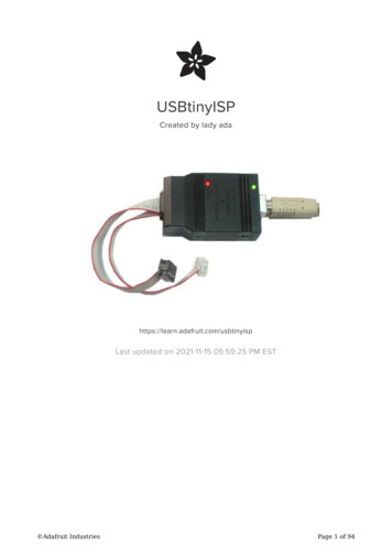
Adafruit 13-20PUwhen purchasedin a kit)IC2Buffer chip(New in v2)74AHC125Page 14 of 94
XTL112.00 MHzceramicoscillatorZTT-12.00MTMake sure itsays 12.00 on it Adafruit IndustriesPage 15 of 94
C1Bypass 0.1uFcapacitor (104)GenericMight be blueC2Bypass 100uF/6.3V electrolyticcapacitor (photoshows 10V but6.3V is fine)GenericNew in v2.0R10 Adafruit Industries10K 1/4W 5%resistor (brown,black orangegold)Page 16 of 94
Adafruit IndustriesR3,R4,R5,R6,R71.5K 1/4W 5%resistor (browngreen red gold)R1,R227-68 ohm 1/4W5% resistorLED1Red 3mm LEDLED2Green 3mm LEDGenericPage 17 of 94
Adafruit IndustriesD1,D23.6V Zenerdiode1N5227BX1USB type Bmale jackGenericJP210 pin boxheader3M 30310-6002HBPage 18 of 94
Adafruit IndustriesJP16 pin straightheader (0.1" x0.1")JP32 pin right angleTyco 640453-2headerJP3'Jumper/ShuntMolex 10-89-7062GenericPage 19 of 94
10 pin IDC cable Adafruit IndustriesGeneric CablePage 20 of 94
6 pin IDC cable Adafruit IndustriesGeneric CablePage 21 of 94
PCB Adafruit IndustriesCircuit boardv2.0 looksdifferent thanv1.0Page 22 of 94
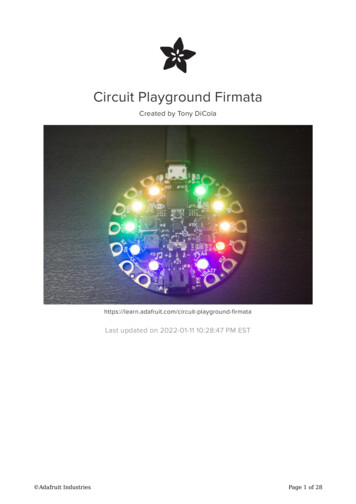
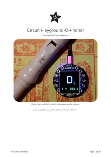
CaseEnclosurePactec CNS-0407Schematic (v2.0)Click to enlarge. Adafruit IndustriesPage 23 of 94
Solder it!Ouch, hot!The first step is to solder the kit together. If you've never soldered before, check the Preparation page for tutorials and more (https://adafru.it/cfd).Check the kit to verify you have all the parts necessary, read the parts page (https://adafru.it/cf1) for a list of parts you should have in your kit. Adafruit IndustriesPage 24 of 94
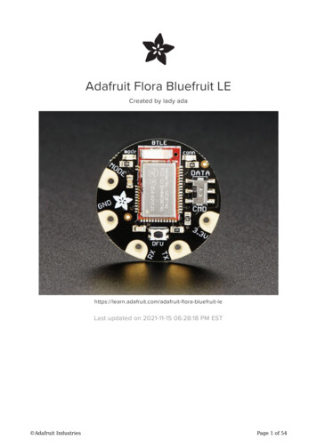
Get your tools ready! A board vise,soldering iron & solder, diagonal cutters,and a solder sucker (desoldering tool) ifyou have one.Next, get ready by placing the PCB in avise so that you can easily place andsolder the parts in!Check also that you have all the toolsyou need, & warm up your soldering ironto 650-700degF.The first part to solder is a resistor, R1.This resistor has a 47ohm value, checkthe parts list to make sure you have theright one. Bend the two legs of theresistor so that its staple-shaped. Thenslide the resistor into the PCB so that theoutline matches the image on thesilkscreen. Resistors are bi-directional soyou don't have to worry about putting itin the wrong way. Adafruit IndustriesPage 25 of 94
Bend the wire legs so that when theboard is flipped over, it won't fall out.Next, with your soldering iron, soldereach of the resistor legs. Place the tip ofthe iron against both the pad (ring) andlead (leg) and after a few counts, touchthe solder in, to make a nice joint.Repeat for the other joint.Next, clip the excess leads using thediagonal cutters. Clip right above the topof the solder joint. Adafruit IndustriesPage 26 of 94
When you are done, it should look likethis. If you have some sticky stuff on thesolder joints, that's OK, that's the rosininside the solder that protects the jointsfrom oxidation. It isn't necessary to cleanit off.Next is the other 47 ohm resistor, R2This one doesnt sit flat like R1, so bend itover as shown. Again it doesnt matterwhich end goes where since resistorswork both ways. Adafruit IndustriesPage 27 of 94
Solder the resistor just like you did withR1.Then clip the excess wire off. Adafruit IndustriesPage 28 of 94
Now that you have a lot of practice withresistors, you can do the remaining 5 allat once. Place R10 (10K pullup resistor),R3, R5 and R6 (1.5K resistors for the USBconnection, LEDs and output buffer).If you are using the UsbtinyISP with aSpokePOV kit, install R4 and R7 (1.5K) aswell. If not you may want to switch theseresistors for jumpers (see the secondphoto for a 'finished' shot) as it will meanthat target boards with loaded pins canbe programmed.Note: sometimes the 74AHC125 is a bitlarger than the silkscreen so you maywant to put R7 in later, once the chip is inplace. Adafruit IndustriesPage 29 of 94
Solder and clip all of the leads. Adafruit IndustriesPage 30 of 94
Next are the two 3.6V zener diodes, D1and D2.These diodes help convert the voltagefrom the microcontroller down to 3.3V,safe for the USB connection.Diodes, unlike resistors, have to beplaced a certain way or they won't workat all. Each diode has a small black line atone end. Make sure that this endmatches with the white line on thesilkscreen image. (See left)Solder and clip the diode leads. Adafruit IndustriesPage 31 of 94
Next is the socket for the microcontrollerthat does all the hard work. A socket isuseful because you can replace the chipin case of upgrade or damage. Socketshave a little notch in them to indicatewhich way to put in the chip. This notchshould match the notch in the silkscreenimage, in this picture, the notch is on theleft-hand side.Tack two opposite corners of the socket,to keep it in place, and then solder all thepins.No clipping is needed as the socket pinsare quite short already. Adafruit IndustriesPage 32 of 94
Next to be placed is the 74AHC125buffer. This chip does a level-shiftingconversion on signals from the USBtinymicrocontroller to the device beingprogrammed. This way you can safelyprogram chips that vary from 1.8V to 5.5Vvoltage.Integrated circuits must be placedcorrectly, check that the notch in the endof the chip matches the notch in thesilkscreen image.When ICs come from the factory, the legsare angled out somewhat which makes itdifficult to insert them into the PCB.Prepare them for soldering by gentlybending the legs against a flat tabletopso that they are perfectly straight.Solder each pin of the buffer, you won'tneed to clip the leads as they are quiteshort already. Adafruit IndustriesPage 33 of 94
Next is the USB connector and the12.00MHz ceramic oscillator. The USBconnector is what we use to plug into thecomputer, the oscillator makes sure theUSBtiny microcontroller runs at theprecise rate necessary to communicateat the very picky USB protocol rates.The oscillator can go in 'either way',they're made to be symmetric. The USBconnector should snap in easily.Solder in the three-pins of the oscillatorand all 6 pins of the USB connector.Make sure to not bridge any of thesquare-pins and put plenty of solder onthe mechanical tabs. These provide theresistance when you plug in a cable soit's important that they are soldered well,as shown here. Adafruit IndustriesPage 34 of 94
Although they are short, you should clipthe pins to the oscillator if possible, tomake sure they dont bend over andtouch another component.Next are the two indicator LEDs, greenLED2 and red LED1. These LEDs let youknow that the USB device connectedsuccessfully, and is in the process ofprogramming the target device.LEDs are diodes, and must be placedcorrectly or they wont light up, which isvery confusing. Make sure the longer(positive) lead of the LED goes into thehole marked with a . See the images tothe left. Adafruit IndustriesPage 35 of 94
The LEDs are also supposed to be veryclose to the top of the enclosure, so thatyou can see the light through the drilledholes, when you bend the leads, makesure the LEDs stick out about 1/2" abovethe PCB.Solder and clip the two LEDs.Next are the two capacitors, C1 and C2.These provide some power supplyfiltering so that the USBtinyISP is lessflakey. C1 goes in the corner next to theUSB connector. It is a non-polar ceramiccapacitor so it can go in either way.C2 is a polarized electrolytic. It must goin only one way. Make sure the longer legof the capacitor goes into the hole with a . Bend the capacitor so that it lies on topof the buffer chip. Adafruit IndustriesPage 36 of 94
Solder and clip both capacitor's leads.Almost done! The last set of parts are theheaders for the cables, and the jumperheader. The 10-pin box header has anotch in it, make sure it matches up withthe silkscreen, as shown.The 6-pin header goes in with the longpins sticking up.The 2 pin jumper has the long pinspointing out. Adafruit IndustriesPage 37 of 94
Solder in all the pins of the headers. Youwon't need to clip them as they arealready quite short.Finally, straighten the pins of themicrocontroller and place it, so that thenotch in the chip matches the notch inthe socket (and the silkscreen) as shown.Now go on to make the cables and putthe PCB in the case.If you're not using the USBtiny to talk to aSpokePOV kit, and if you are using atarget that has some load on the SCKand MOSI pins, you may need to replaceR4 and R7 with jumpers as the 1.5Kresistors will have trouble driving theload!Make 6-pin cable (Old kits, without pre-made 6-pincables)There are two standards for AVR programming, 6-pin and the 10-pin headers.Therefore, it's important that an AVR programmer have both types of cables. The 10pin cables are easy to come by, but the 6-pin ones must be custom made. However,making a cable is super easy, just follow these steps! Adafruit IndustriesPage 38 of 94
If you're using the adaptor for a spokepov or don't need the 6pin cable, you can justskip this part.It's hard to find 6-conductor ribbon cableso you may end up with 10-conductorwire. (The kit ships with 6-conductor) Ifso, just use your diagonal cutters (or aknife) to cut a notch so that the red stipeis on the 6-conductor side.Tear the cable, it should come apartcleanly.You are now ready to assemble thecable. Adafruit IndustriesPage 39 of 94
It's important that the key (the bump inthe connector) and the red stripe line up.Match the image on the left, just poke theconductor in with a mm or two past theedge.Get it started by just squeezing it withyour fingers to make sure the wires arealigned properly. You won't be able tofinish the cable this way so dont try!Do not use needlenose pliers to try topress the pieces together. You have tohave very flat pressure from both sides.For example, use the flat side of a tool topress against a table top.Or better yet, a vice! Slowly squeeze thetwo sides together until they lock. Adafruit IndustriesPage 40 of 94
Do the other end, keeping track of thekey and red line.Yay! You've got two cables!CaseFinally it's time to put the programmer in the case for use.Take the PCB, two case halves and thecables you've made. Adafruit IndustriesPage 41 of 94
Plug in the two cables as shown, the redstripes on top and so that the cablesdon't bend over the plug (the case wontfit).Put the PCB into the bottom case half.The 6-pin cable may have strain reliefsthat can clip on. You don't really needthem but if you do want strain relief, put iton the one that goes to the target: thecable won't fit in the case if the strainrelief bit is on.Line up the LEDs and snap the top on.You're done!Next up, read the usage manual (https://adafru.it/cfg).Can't get it working? Don't worry, help is available in the forums (https://adafru.it/forums)! Adafruit IndustriesPage 42 of 94
Parts (v1.0)Kit parts listThis is the list for very old kits, its very unlikely you have av1.0 but we're keeping it around for historical recordImage Adafruit IndustriesName mmed ATTINY2313-20PUwhen purchased Digikey & Mouserin a kit)XTL112.00 MHzceramicoscillatorZTT-12.00MTPage 43 of 94
C1Bypass 104capacitor (0.1uF)BC1160CT-NDMight be blueBrownGreenRedGold.gif Adafruit IndustriesR1010K 1/4W 5%resistor (brown,black orangegold)10KQBK-NDR3,R4,R5,R6,R71.5K 1/4W 5%resistor (browngreen red gold)1.5KQBK-NDR1,R227-68 ohm 1/4W5% resistor47QBK-NDPage 44 of 94
Adafruit IndustriesLED1Red 3mm LEDLTL-1CHELED2Green 3mm LED LTL-1CHGD1,D23.3V Zenerdiode1N5226BPage 45 of 94
Adafruit IndustriesX1USB type Bmale jackJP210 pin boxheader61729-0010BLFPage 46 of 94
Adafruit IndustriesJP16 pin straightheaderJP32 pin right angle Mouserheader(640453-2)JP3'Jumper/ShuntMolex 10-89-7062Mouser(71363-102LF)Page 47 of 94
Adafruit Industries10 pin IDC cableDigikeyMouser6" wire ribboncable (6conductors)DigikeyPage 48 of 94
6-pin IDC plug Adafruit IndustriesFCI 71600-006LFMouserPage 49 of 94
PCB Adafruit IndustriesCircuit boardAdafruit IndustriesPage 50 of 94
Pactec CNS-0407Case Adafruit IndustriesEnclosureMouserPactecPage 51 of 94
Solder (v1.0)V1.0 instructions!These are instructions for v1.0 USBtinyISP. If your PCB looks a bit different, youprobably have a v2.0 and should go here for the instructions (https://adafru.it/cf2).Its very unlikely you have a v1.0 but we're keeping itaround for historical recordSolder it!The first step is to solder the kit together. If you've never soldered before, check the Preparation page for tutorials and more (https://adafru.it/cfd). Adafruit IndustriesPage 52 of 94
Check the kit to verify you have all theparts necessary (the 0.1uF capacitor ismissing, oops!).Get your tools ready! A board vise,soldering iron & solder , diagonal cutters,and a solder sucker (desoldering tool) ifyou have one.Put the PCB in the vise & heat up thesoldering iron so you are ready to go!Place the first component: the 10Kresistor as shown. Resistors are nondirectional, so you can put them in'either' way and they'll work fine. Whenyou put the legs through the PCB, bendthem out so when the PCB is flipped itwont fall out. Adafruit IndustriesPage 53 of 94
Flip the PCB over.Solder the legs. Hold the tip of ironagainst the wire leg and the metal ring atthe same time, after 2 counts, poke thesolder in till it creates a nice pool. Thenremove the solder, wait a half count, thenremove the iron. Do this for both legs. Adafruit IndustriesPage 54 of 94
Use the diagonal cutters to clip the legsoff just above the solder joint. Adafruit IndustriesPage 55 of 94
Next up are the 2 47 ohm resistors. Placethem as shown. Bend the legs out, flipthe PCB, solder the 4 joints and clipthem. Adafruit IndustriesPage 56 of 94
Adafruit IndustriesPage 57 of 94
Next are the 5 1.5K resistors. Place themas shown, then solder them in and clipthe leads off. Adafruit IndustriesPage 58 of 94
Next are the zener diodes. Diodes aredirectional so make sure to put them inas shown. There's a white stripe on thePCB drawing that matches the black stipeon the glass diode. Adafruit IndustriesPage 59 of 94
The next parts are the USB connector(big silver part), the 12.00MHz ceramicoscillator (the three pin part) and theceramic capacitor (the small yellow part).Both the capacitor and oscillator arenondirectional so they can go in eitherway. The USB connector can only go inone way, and snaps into place.When you solder in the parts, make surethat you put plenty of solder on the twoprongs that hold the USB connector in.These are mechanical connections: thesolder actually acts as a 'glue' here,keeping the part fixed in place! Adafruit IndustriesPage 60 of 94
Next are the headers and themicrocontroller socket. The 6-pin headerhas no direction so just put it in eitherway.The 10-pin box header has a notch whichshould match the notch in the PCBgraphic. (here it's closest to themicrocontroller socket).The right angle header JP3 should go inas shown, with the two prongs stickingout over the PCB.The microcontroller socket also has to goso that the notch in the end matches thedrawing. Here it's on the right. If youmess it up it's not the end of the world,just remember to put the microcontrollerin the right way!When you solder it in, it might be toughto keep the parts in place. you can try'tacking' the parts in place by holding it inwith a finger and soldering one or twocorners as shown.Then go back and solder each and everyconnectionThe two LEDs are next. They shouldstand-off a bit from the PCB so make amarking about 1/2" (1cm) from where thecolored plastic ends. Adafruit IndustriesPage 61 of 94
Place the LEDs as shown, the red onenear the 10-pin header and the greenone near the USB plug.LEDs are directional and if you put themin backwards they won't light up. Tofigure out which way is right, look on thePCB, at the image of the LED. One sideof the image is slightly flattened. Thatindicates the negative side. The LEDshave one lead that is shorter than theother. The short lead is also negative.In this image, the negative side for thegreen LED is on the left. The negativeside for the red LED is towards the top.Instead of making the LEDs sit flatagainst the PCB, bend the leads at the1/2" mark you made so they stick out.Solder them in place. Adafruit IndustriesPage 62 of 94
Soldering's done. Next up, insert themicrocontroller. You can do this by gentlybending the legs in using your fingertipsor the tabletop.Make sure it's inserted as shown, andpress it in so it's seated well into thesocket.Make 6-pin cableThere are two standards for AVR programming, 6-pin and the 10-pin headers.Therefore, it's important that an AVR programmer have both types of cables. The 10pin cables are easy to come by, but the 6-pin ones must be custom made. However,making a cable is super easy, just follow these steps!If you're using the adaptor for a spokepov or don't need the 6pin cable, you can justskip this part.It's hard to find 6-conductor ribbon cableso you may end up with 10-conductorwire. (The kit ships with 6-conductor) Ifso, just use your diagonal cutters (or aknife) to cut a notch so that the red stipeis on the 6-conductor side. Adafruit IndustriesPage 63 of 94
Tear the cable, it should come apartcleanly.You are now ready to assemble thecable.It's important that the key (the bump inthe connector) and the red stripe line up.Match the image on the left, just poke theconductor in with a mm or two past theedge.Get it started by just squeezing it withyour fingers to make sure the wires arealigned properly. You wont be able tofinish the cable this way so don't try! Adafruit IndustriesPage 64 of 94
Do not use needlenose pliers to try topress the pieces together. You have tohave very flat pressure from both sides.For example, use the flat side of a tool topress against a table top.Or better yet, a vice! Slowly squeeze thetwo sides together until they lock.Do the other end, keeping track of thekey and red line.Yay! You've got two cables! Adafruit IndustriesPage 65 of 94
CaseFinally it's time to put the programmer in the case for use.Take the PCB, two case halves and thecabl
Nov 15, 2021 · and tested under Windows, Linux and MacOS X. Perfect for students and beginners, or as a backup programmer. The project is based off of the USBtiny code & design (https://adafru.it/cf5). The main improvements are: adju