Transcription
Circuit Playground Sound-ControlledRobotCreated by Anne d-sound-controlled-robotLast updated on 2022-06-15 04:46:51 PM EDT Adafruit IndustriesPage 1 of 31
Table of ContentsIntroduction3Robot Mechanics4 Body Wheels Servo Cables456Add Circuit Playground7Using the Microphone10Continuous Rotation Servos14Whistle Bot16 Using the Whistle Bot Variations on the Whistle Bot2020Tone Controlled Robot20Build the Controller24Use29Going Further29 Control Robotics Adafruit Industries2930Page 2 of 31
IntroductionCircuit Playground, Adafruit's multi-faceted experimenter board, may be used in manyof the maker projects on the Adafruit Learning System and other tutorials on theInternet. This project extends Circuit Playground into the field of robotics.With this project, you can make a robot with Circuit Playground that is low cost, easyto build and program. The techniques used are applicable to using continuous servos,sound processing, and robotics techniques.There are two general methods of controlling robots: via a set of wires from a personto the robot or wirelessly in some fashion. While Circuit Playground contains aplethora of capabilities, a wireless radio is (currently) not onboard. Looking at theinput sensors shows two which might allow non-wired control: the light sensor andthe sound sensor. The light sensor could be a challenge to use as a control,especially in bright light. I believe there is more flexibility with the microphone.At present, use of a Alexa/Siri type voice control system takes more processing powerthan is available on the Circuit Playground's ATmega 32u4 microcontroller. CircuitPlayground is very able to listen for tones at certain frequencies with the capabilitiesbuilt into the Circuit Playground software library. Adafruit IndustriesPage 3 of 31
This project is intended to be educational, so there is more detail on how the variousparts of the project work. This includes optimal sound values for controlling the robotand how to set the servo motors for no movement. The data gathered in those stepswill be used in building the final robot.Robot MechanicsBodyIn guilding a simple body, we can just attach the servo motors back to back. Thisis done using three or four 2.5" / 6.5 mm long screws. You will need 3 nuts for eachone so that the head and one nut grips one servo and other two nuts grip the other.Alternatively you can cut two pieces of wood. Nominal measurements are 2 inches /57 mm ling by 0.75" / 20 mm by 0.25 inch / 8 mm tall. You may want to measure thespace between servos yourself to ensure a snug fit. You can also look to 3D print anappropriate piece. Measuring carefully, possibly with a caliper, is recommended if youdesign a custom piece. Align to the top and bottom of the servos where the mountingholes are and secure with wood or self tapping screws.The secured servos serve as a rigid body for mounting other parts including a minibreadboard on one side and a LiPo battery and Circuit Playground on the other. Adafruit IndustriesPage 4 of 31
WheelsI designed the robot to sit pretty close to the ground but this is a design decision youcan change without any consequences. I could not source wheels approximately 100mm in diameter with a Futaba/Parallax servo mount, so I made my own. You cansource wheels if you like from a shop specializing in robotics.Using good stiff cardboard, I made circles with a diameter of 3.75 inches / 95 mm. Youcan find a can or other round shape at least this size to trace around. You can alsodraw a circle with a compass. Be sure the circle is nice and round when you cut it outas any flat spots will not allow the robot to roll well. Cut out two circles.To find the center of the circle, I suggest following this tutorial on instructables.com (https://adafru.it/rMf) or you may Google "Find center of a circle". Using a servo screw tocarefully poke through and make a hole at the center point only large enough for thescrew. If you have some tiny lock washers, they can help keep the wheels screwstight. If the robot is not moving when the servos spin, check the wheel center screwsto ensure they are tight. Adafruit IndustriesPage 5 of 31
Servo CablesAs this is an educational build, I did not cut the generous length of servo cable oneach motor. Rather the excess is folded and secured with a wire tie and tucked it ontothe top of the servo.While technically these servos require 5V power to run, you can get away withrunning them from 4V power like the LiPo, and they'll work OK! They'll just run a littleweak/slow. Adafruit IndustriesPage 6 of 31
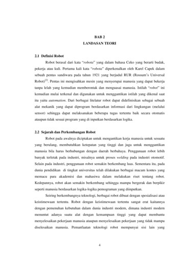
Leave enough slack at the end to just touch the mini breadboard. The ends of theservo cables will be mounting to one side of the breadboard.Add Circuit PlaygroundThe Fritzing diagram for the robot is shown below. The number of parts andconnections is fairly low. Hookup wire for the breadboard makes for sturdierconnections than premade breadboard wires.The alligator clip to male jumpers allow connection between the Circuit Playgroundand the robot. You can buy them from Adafruit as part #3255 or make them yourselffrom clips and pins. Adafruit IndustriesPage 7 of 31
Peel the adhesive off the mini breadboard (or put some adhesive on the back if thebreadboard lacks it) and stick to one side of the robot body defined by the twoservos. This will be our wiring side.We need to attach the servo leads to the board as shown. Cut individual 90 degreeheader pins and take off the plastic square. Make 6 of them. Place them on thelocations in the 4th row from the top with the ends pointing to the "top" defined aswhere the servo wires are at. This allows for good breadboard and servo cableconnections. Add red and black solid wire to be able to power the servos off thesame battery voltage.Next add the alligator clips, connecting the two white servo control wires and the twojoined power lines. I suggest Black for ground GND, red for power VBATT, and twoother colors for the servo control wires. In the picture below, I did not have the newlystocked Adafruit multicolor cables. Adafruit IndustriesPage 8 of 31
Take the LiPo battery and stick it to the non-breadboard side of the robot body withthe power lead sticking out towards the left wheel. Use Blu Tack, thick double-sidedtape or other non-permanent adhesive. Place additional non-permanent adhesive onthe back of the Circuit Playground board and carefully press it onto the battery at a45 degree angle.The Circuit Playground should be up a bit so that when we drape the alligator clipsover from the breadboard side, they comfortably clip onto the 4 top pins (one reason Adafruit IndustriesPage 9 of 31
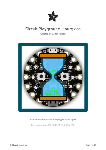
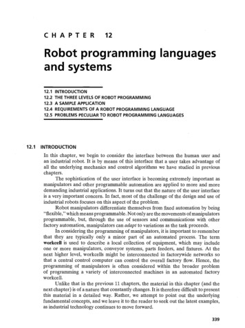
we tilted the board at 45 degrees, the other two being good for the power and USBconnectors).The joint red connections on the breadboard go to the Circuit Playground VBATTconnection. The joint black connections use the clip that is connected to the CircuitPlayground GND connection. The right motor (looking from the breadboard side) goesto Pin #6 and the left motor connection to Circuit Playground Pin #12.That's it. Check your connections against the diagram and pictures to be sureeverything matches up.Using the MicrophoneIt sounds like it would be an easy task: make a certain sound and have themicrophone detect it and some software makes a decision based on what themicrophone just heard. But most sounds are polyphonic, made up of many differentsounds at multiple frequencies. This is very hard to match up in software.But our microcontroller can match monophonic, single frequency sounds. It still is notso easy. You need to take into account a sound occuring over time. So to simplify asound's identification, we want to convert the microphone input to the frequencydomain. If we know the likely frequency of a sound, we can more easily compare it tothe sound frequency you expect.What is the method we transform sound to frequency? There are severalmethematical transformations that take intensities sensed over time and calculate aset of frequencies. The main method is called the Fast Fourier Transform (commonlyabbreviated as FFT). For more in-depth information, see this Adafruit Learning Centertutorial (https://adafru.it/qMB) and Wikipedia (https://adafru.it/qMC).XKCD-style graph generated by http://matplotlib.org/users/whats new.html#xkcdstyle-sketch-plotting (https://adafru.it/cM8) by Tony DiCola. Adafruit IndustriesPage 10 of 31
In the diagrams, you can see a continuous line graph transforms to a bar graph. That'spart of the math. We look for the tallest bar and see where it lands on the x-axis whichis the frequency of the sound.The Circuit Playground library has a FFT routine built-in for our use. The routineCircuitPlayground.mic.fft takes in sound samples and puts the frequencies itfinds into 32 frequency bins using some math. To make sure we find the sound we arelooking for (as things can change over time), several samples are taken and averaged.Which of the 32 frequency bins corresponds to sounds we might want to make? Iused the list of musical notes in the tutorial Circuit Playground Sound and Music (https://adafru.it/qMD) as a start. But I found I was not getting good results.The best frequencies to use are shown in the chart below. If you would like toperform sound tests or just have fun, here are the simple circuits and programyou can use.I grabbed an Arduino Uno (http://adafru.it/50) and created one of my "go to" circuitswhich reads a variable resistor and maps the values to a range of frequency tones tooutput to a piezo speaker. You can also use a second Circuit Playground as shown inthe center diagram, either using an external piezo speaker or the internal speaker.The value of the potentiometer is not critical, any one from 1 kiloohms to 100 kiloohmsor more will work fine as it acts as a voltage divider to select different voltages on ananalog pin which is translated to variable pitch on the speaker.// Variable Tone Generator Circuit for Arduino Uno or Circuit Playground// Anne Barela for Adafruit IndustriesSeptember, 2016#define speakerPin 11 // For Circuit Playground change 11 to 9 for// external Piezo, change to 5 for onboard speaker#define potPin A0// For Circuit Playground change A0 to A7void setup() { Adafruit IndustriesPage 11 of 31
pinMode(potPin, INPUT);pinMode(speakerPin, OUTPUT);Serial.begin(9600);}void loop() {uint16 t potValue;uint16 t freq;potValue analogRead(potPin);freq );Serial.println(freq);}Test out your tone generator by turning the potentiometer and listening to thedifferent tones. Hooking up a serial monitor to the USB port, you can see thefrequency you have dialed in.On the "listening" Circuit Playground, you use the onboard microphone and see whichfrequency bins "max out" (like the peak in the above bar graph) as it "hears" the soundfrom the sound generator circuit.For the "listening" Circuit Playground, download the following code:// Fast Forier Transform Test Program for Circuit Playground// Anne Barela for Adafruit IndustriesSeptember, 2016#include Adafruit CircuitPlayground.h #define BINS32#define FRAMES 4// The number of FFT frequency bins// This many FFT cycles are averagedvoid setup() d loop() {uint8 t i,j;uint16 t spectrum[BINS];uint16 t avg[BINS];// Set up the board library and serial// FFT spectrum output buffer// The average of FRAME "listens"for(j 1; j FRAMES; j ) {// We gather data FRAMES times andaverage itCircuitPlayground.mic.fft(spectrum); // Here is the CP listen and FFT thedata routinefor(i 0; i BINS; i ) {// Add for an averageif(spectrum[i] 255) spectrum[i] 255; // limit outlier dataif(i 0)avg[i] spectrum[i];elseavg[i] avg[i] spectrum[i];}}for(i 0; i BINS; i ) {// For each output bin averageavg[i] avg[i] / FRAMES;// divide about the number of valuesaaveraged}int maxVal 0, maxIndex 0;for(i 0; i BINS; i ) {// For each output bin average Adafruit IndustriesPage 12 of 31
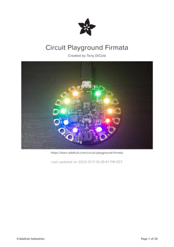
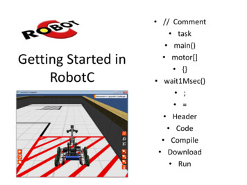
if(avg[i] maxVal) {maxVal avg[i];maxIndex i;}}for(j 0; j 32; j ) {Serial.print(avg[j]);Serial.print(" ");}Serial.println("");//find the peak value//and the bin that max value is in// print spectrum 32 bins// and print the highest value and the bin it isinSerial.print("Max Value "); Serial.print(maxVal);Serial.print(", Index of Max Value "); Serial.println(maxIndex);}Find a room where people will not be annoyed by squeeky sounds and is quiet. Letthe far right "listening" Circuit Playground listen to the ambient sounds with thesecond sketch and a computer to monitor the serial output. Then use your tonegenerator to make tones.You can use the same computer with a separate USB port and serial terminal programto monitor the frequency you chose dial in. Adjust the potentiometer and note wherea FFT bin reaches a maximum (hopefully 255, but maybe greater than 220 or so) andwrite that frequency and that bin number as a data point. Continue through the fullrange of the potentiometer. I recorded the following values and made a quick plot.Several different frequencies maxed out an FFT bin. The data shows that you can getthe same bin filling at different frequencies. Those frequencies are about 3 times alower value (a third harmonic in musical/frequency terms). But not all frequencies willmax out a bin. That's why my first inclination to pick nice musical notes didn't worklike I thought. Several candidate frequencies (#1 to #5) are chosen to use for therobot. Those bins are spaced out so one tone that might be close to another does notget so close that the code cannot differentiate one for another. Adafruit IndustriesPage 13 of 31
Continuous Rotation ServosThe robot uses two continuous rotation servos (http://adafru.it/154) to move. Thesemotors are a bit different than normal servos. See the Adafruit Motor Selection Guideon continuous servos (https://adafru.it/qME) for a great explanation for how they work.The two servos we are using are rotated 180 degrees to each other (back to back) soone side will be running opposite the other. For example to go forward, run one servoforward, the other in reverse.Using the Servo.write function, a setting of 180 is full forward, 0 is full reverse.The value for no motion would usually be 90 degrees but each servo might be a bitdifferent. We need to do a bit of testing to find the actual angle for a stop value forthe servos you get.The program below uses the Circuit Playground to find the values for two Servosconnected back to back. If the slide switch is on " ", the right motor is calibrated, "-"for the left motor. The two pushbuttons adjust the right motor by 0.1 degree (leftminus, right plus). The angle is printed out on the Arduino serial monitor.Use the circuit shown on the page "Use Circuit Playground" and the program below.// Circuit Playground Robot - Continuous Servo zero/no movement calibration program// Anne Barela for Adafruit IndustriesSeptember, 2016#include Adafruit CircuitPlayground.h #include Servo.h Servo servoLeft;Servo servoRight; Adafruit Industries// Define left servo// Define right servoPage 14 of 31
float speedAngleLeft 90.0; // Assume 90 degrees as a startfloat speedAngleRight 90.0;void setup() al.println("Robot Continuous}Set left servo to digital pin 12Set right servo to digital pin 6initialize the Circuit Playground libraryto output servo angle valuesServo Zero Movement Calibration");void loop() {// Loop through motion testsSerial.print("Speed Left ");Serial.print(speedAngleLeft);Serial.print(", Speed Right "); nd.slideSwitch()) { // Calibrate Right, - Calibrate Leftif( CircuitPlayground.rightButton() ) {speedAngleRight 0.1;}if( CircuitPlayground.leftButton() ) {speedAngleRight - 0.1;}}else {if( CircuitPlayground.rightButton() ) {speedAngleLeft 0.1;}if( CircuitPlayground.leftButton() ) {speedAngleLeft - rite(speedAngleRight);delay(50);}To use the program, upload it to your Circuit Playground with the right servo controlwire connected to Pin #6 and the left servo control motor connected to Pin #12.When you power on the project, both wheels will probably turn slowly. Maddeningthat they do, as at an angle of 90 degrees we'd think they should be stopped. Butwe'll fix that.Move the slide switch to and open the Arduino IDE serial monitor to view the rightmotor angles. Press the Circuit Playground push buttons to increment or decrementthe angle given to the right servo. The switches are not debounced so the valuesmight be a bit jumpy. Eventually the motor will stop at a certain value displayed on theserial monitor. Note that value for right.Move the slide switch to - and do the same angle adjustment for the left motor.Record the left value which results in no movement. For my two servos, the angleswere 96.2 for the left servo, 95.3 for the right.You can hard code these into the main robot program. If you leave the values I foundinstead of using your own, you'll probably still have slowly turning wheels at a stop.All continuous servos are a bit different. Adafruit IndustriesPage 15 of 31
Whistle BotWhen working with what frequencies the robot responds to, the temptation is towhistle into the microphone and see what it does. This is what I did in uploading theCircuit Playground sample program vu meter (https://adafru.it/qPb) which uses themicrophone as a sound level meter. I did get some multicolor sounds with differentwhistles.But do whistles allow you to control the robot? Maybe, if you are good at yourwhistles. Through testing the various bins my whistling fell in, I could get decent startand stop whistles. If I whistle in a frequency filling bins 5, 6, or 7, the robot movesforwards. A different, higher whistle filling one of the bins 8, 9, or 10, the robot stops.My whistles are not varied enough to get left and right turns. If you have some rangeof tones, you can change which bins make which motion in the program's switchstatement.For the most flexible sound control, consider the tone controlled robot on thenext page.Here is the code for a two tone whistle bot. A lower tone starts the robot movingforward, a higher whistle stops the robot.// A sound controlled robot for the Adafruit Circuit Playground board// This uses two continuous rotation servos for movement and listens to// commands via the built-in mic.// This version is designed to respond to two whistle tones for//start and stop.// By Anne Barela for Adafruit Industries September, 2016#include Adafruit CircuitPlayground.h #include Servo.h // Circuit Playground library// Audiono servo control library// Global Definitions ---------// Fourier Transform#define BINS32// FFT output is output in this many bins#define FRAMES4// This many FFT cycles are averaged for leveling#define THRESHOLD 150// Max bin value to say a tone was detected// Servo objectsServo servoLeft;#define leftStopAngle 96.2Servo servoRight;#define rightStopAngle 95.3uint8 t moving 0;yes)//////////Define left servoAngle that left servo will stop (calibrated)Define right servoAngle that right servo will stop (calibrated)Is the robot currently moving value (0 no, 1 // SETUP FUNCTION - this runs once to set the robot up when it is powered onvoid setup() Playground.begin(); Adafruit Industries// Set left servo to digital pin 12// Set right servo to digital pin 6// Initialize the CP libraryPage 16 of 31
CircuitPlayground.setBrightness(20); // NeoPixels are another visual que on whatis happeningCircuitPlayground.clearPixels();// Ensure all NeoPixels are off at startSerial.begin(9600);// Set up the USB port for serialinformation for usersSerial.println("\n\nAdafruit Circuit Playground Robot using Whistle Commands");stopRobot();}// LOOP FUNCTION - runs over and over to check what to do --------------------void loop() {uint8 t i,j;uint16 t spectrum[BINS];uint16 t avg[BINS];iterationsint16 t maxVal 0, maxIndex 0;valueint8 tmaxBins;// loop index values// FFT spectrum output buffer// The avaerage FFT values over FRAMES// The maximum value and the FFT bin of thatif( !CircuitPlayground.slideSwitch() ) {shut robot downif(moving) al.println("\nRobot stopped due toreturn;}// if slide switch is moved to "-",// stop the robot// turn all pixels off in low power modeslide switch, move to ' ' to resume");// and go back to top of loopfor(j 1; j FRAMES; j ) {// Gather FRAMES samples of audio from themicrophoneCircuitPlayground.mic.fft(spectrum); // This function gathers an audio sampleand does FFTfor(i 0; i BINS; i ) {// Add values to perform a simple averageif(spectrum[i] 255) spectrum[i] 255; // in library, sometimes values get"huge"if(i 0)avg[i] spectrum[i];elseavg[i] avg[i] spectrum[i];}}for(i 0; i BINS; i ) {// For each output bin averageavg[i] avg[i] / FRAMES;//calculate the average (unweighted)}maxBins 0;for(i 0; i BINS; i ) {// Search for the highest value and the FFT bin it'sinif(avg[i] 255) avg[i] 255;// HACK 4 NOWif(avg[i] maxVal) {maxVal avg[i];// Important note: If there is an equal max value inhigher binsmaxIndex i;//note the later index (helps when recognizing asound)}if(avg[i] 254) maxBins ;}// avg[] is now FRAME averaged FFT output, 32 bins.if( CircuitPlayground.leftButton() ) {behaviormaxIndex 9; // stopmaxVal THRESHOLD;}if( CircuitPlayground.rightButton() ) {maxIndex 7; // forwardmaxVal THRESHOLD; Adafruit Industries// use onboard buttons to changePage 17 of 31
}// A detection is defined as a bin reaching a value of at least THRESHOLDif( maxVal THRESHOLD ) {// For visual review of the values the FFT has produced, print the FFTs 32 binsfor( uint8 t j 0; j 32; j ) {Serial.print(avg[j]);Serial.print(" ");}Serial.println("");// maxVal is the biggest bin, maxIndex is the index of that valueSerial.print("\nMax Value "); Serial.print(maxVal);Serial.print(", Index of Max Value "); xels(); // clear old pixel valuesswitch( maxIndex ) { // based on which bin had the detection, act on itcase 0:case 1:case ;// you can put a movement function call herebreak;case 3:case ;// you can put a movement function call herebreak;case 5:case 6:case 0); // Low whistle(3rd LED Green)forward();// forwardbreak;case 8:case 9:case 10); // higherwhistle (4th LED red)stopRobot();break;case 11:// 7822 ,0);// you can put a movement function call herebreak;case 18:case 19: CircuitPlayground.strip.setPixelColor(4,0,240,0); // 2795 hertz// you can put a movement function call herebreak;case 20:// 2957 hertzcase 21:// 3094 hertzcase 22: CircuitPlayground.strip.setPixelColor(5,0,240,0); // 3250 hertz// you can put a movement function call herebreak;case 23:// 3436 hertzcase 24:// 3605 hertzcase 25: CircuitPlayground.strip.setPixelColor(6,0,240,0); // 3700 hertz// you can put a movement function call herebreak;case 26:// 3876 hertzcase 27:// 4046 hertzcase 28: CircuitPlayground.strip.setPixelColor(7,0,240,0); // 4192 hertz(motor noise?)// you can put a movement function call herebreak;case 29:// 4339 hertzcase 30:// 4517 hertz Adafruit IndustriesPage 18 of 31
case 31: CircuitPlayground.strip.setPixelColor(8,0,240,0); // 4640 hertz(often goes here)// you can put a movement function call herebreak;default: CircuitPlayground.strip.setPixelColor(9,200,0,0); // if any otherbin, light NeoPixel #9 redbreak;} // end switchCircuitPlayground.strip.show(); // show the neopixel assigned to the bin} // end if} // end function loop// Servo motion function routines for robot movement forward, reverse, turns, andstopvoid stopRobot() {moving rightStopAngle);90.0Serial.println("Stopped");}// let program know we are stopped// Get these values from a calibration routine// as continuous servos don't stop at exactlyvoid forward() {if( moving 1 ) { // if the robot currently is movingstopRobot();// stop it}else {moving 1;// flag we are going to DED?void reverse() {if( moving 1 ) { // if the robot currently is movingstopRobot();// stop it}else {moving 1;// flag we are going to d turnRight() {if( moving 1 ) { // if the robot currently is movingstopRobot();// stop it}else {moving 1;// flag we are going to oid turnLeft() {if( moving 1 ) { // if the robot currently is movingstopRobot();// stop it}else {moving 1;// flag we are going to move}servoLeft.write(0);servoRight.write(0);} Adafruit IndustriesPage 19 of 31
Using the Whistle BotUse a lower tone whistle to start it forward, a higher whistle to stop. You'll probablyneed to experiment with your whistle tones to find the right ones. It currently iscalibrated for more of a male whistle (I'm told by my wife).Whistle and see which NeoPixels light up. For me it's the 4th and 5th pixels (#3 and#4). If you see something like the second and third (NeoPixels #2 and #3), you canchange where the movement function calls are in the switch.case statement(there are comments where to put the calls in).The left and right pushbuttons perform the same two functions (start & stop) if youwould like to manually change the mode. If you change the switch.casestatement, put the case numbers in the if statements that check the left and rightbuttons on Circuit Playground.Here is a video of the whistle bot in action:Variations on the Whistle BotYou could use a first low tone for start and a second low tone for stop. You would testif variable moving is 1 then you's call stopRobot instead of forward . Then youhave the higher tone to do something like calling reverse .If you can whistle in three tones, you can probably call all of the control functions withsome variables which record what state you are in and what state you want the robotto change to when a whistle is received.On the next page you can build an inexpensive tone generator to save you fromhaving to whistle so precisely.Tone Controlled RobotThe final program for the robot combines the building blocks we've worked on in thetutorial: Using the Circuit Playground library for microphone, NeoPixel, and switchfunctions Taking FFT information and looking for our command sounds Adafruit IndustriesPage 20 of 31
Moving the robot based on the command soundsYou might want to review how to program Circuit Playground (https://adafru.it/rb4).And definitely use a good USB data cable and not a charging cable (even I have donethis and said "doh!").Here is the code to run on the Circuit Playground for the tone controlled robot:// A sound controlled robot for the Adafruit Circuit Playground board// This uses two continuous rotation servos for movement and listens to// commands via the built-in mic. Sound processing is done with the// Circuit Playground FFT library function for AVR microcontrollers.// The fast Fourier transform (FFT) algorithm converts a signal from the// time domain to the frequency domain -- here, turning a specific audio// signal into a command to the robot.// Note the Circuit Playground slide switch when set to "-" stops the motors// It is not a battery off switch so unplug or turn off the battery to save// power when not in use.// By Anne Barela for Adafruit Industries September, 2016#include Adafruit CircuitPlayground.h #include Servo.h Version 1.0// Circuit Playground library// Audiono servo control library// Global Definitions ---------// Fourier Transform#define BINS32// FFT output is output in this many bins#define FRAMES4// This many FFT cycles are averaged for leveling#define THRESHOLD 150// Max bin value to say a tone was detected// Servo objectsServo servoLeft;#define leftStopAngle 96.2Servo servoRight;#define rightStopAngle 95.3uint8 t moving 0;yes)//////////Define left servoAngle that left servo will stop (calibrated)Define right servoAngle that right servo will stop (calibrated)Is the robot currently moving value (0 no, 1 // SETUP FUNCTION - this runs once to set the robot up when it is powered onvoid setup() {servoLeft.attach(12);// Set left servo to digital pin 12servoRight.attach(6);// Set right servo to digital pin 6CircuitPlayground.begin();// Initialize the CP libraryCircuitPlayground.setBrightness(20); // NeoPixels are another visual que on whatis happeningCircuitPlayground.clearPixels();// Ensure all NeoPixels are off at startSerial.begin(9600);// Set up the USB port for serialinformation for usersSerial.println("\n\nAdafruit Circuit Playground Robot");stopRobot();}// LOOP FUNCTION - runs over and over to check what to do --------------------void loop() {uint8 t i,j;uint16 t spectrum[BINS];uint16 t avg[BINS];iterationsint16 t maxVal 0, maxIndex 0; Adafruit Industries// loop index values// FFT spectrum output buffer// The avaerage FFT values over FRAMES// The maximum value and the FFT bin of thatPage 21 of 31
valueint8 tmaxBins;if( !CircuitPlayground.slideSwitch() ) {shut robot downif(moving) al.println("\nRobot stopped due toreturn;}// if slide switch is moved to "-",// stop the robot// turn all pixels off in low power modeslide switch, move to ' ' to resume");// and go back to top of loopfor(j 1; j FRAMES; j ) {// Gather FRAMES samples of audio from t
Circuit Playground, Adafruit's multi-faceted experimenter board, may be used in many of the maker projects on the Adafruit Learning System and other tutorials on the Internet. This project extends Circuit Playground into the field of robotics. With this project, you can make a robot with Circuit Playground that is low cost, easy to build and .