Transcription
quicky 3ds max 7 tutorial v1.0ghazJuly 4, 20061
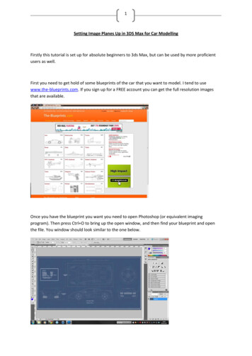
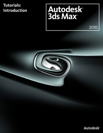
Figure 1: the viewport layoutThis tutorial is for those who know as much about 3ds Max as I did whenI got started. Absolutely nothing. So we will start from scratch and endup with a textured non-animated model (.MDL) that you can use for Fate.There are definately better ways of doing it, but I’ll show you what worksfor me while also using as many different 3ds max stuff as possible. I alsoadvise you to make a brand new save after each big step. That way you canalways go back to an old saved file if something goes wrong.First I want to make sure that you viewport is setup the same as mine. Itshould be the same as the default, but just to make sure go to Customize V iewport Conf iguration. If you click on the Layout tab, it should look likeFigure 1. If it does not, click on the viewport picture to change it.In Figure 2 you can see some of the important buttons. I will refer to thesea lot. Red is select, green is move, blue is rotate and pink is scale. Thisis also a good time for you to learn some other basic controls. Middle-mousebutton pans the ‘camera’. Mousewheel zooms in and out. Middleclicking ona view selects that view without losing your current object selection. Other2
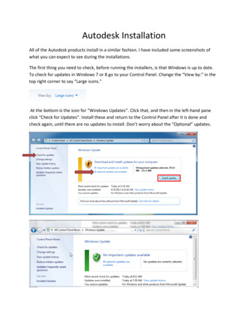
Figure 2: important buttonsFigure 3: creating in top viewuseful controls are in the bottom-right corner of the screen, pan, zoom,rotate view etc. Just note that rotate view rotates the ‘camera’, while therotate in Figure 2 physically rotates your object. If you just want to seeyour object from a different angle, use the rotate in the bottom-right corner.Pressing F3 and F4 turns shading and wire mode on and off. So if the objectin one of my screenshots is solid while yours is a wireframe, press F3.OK, time to start with our axe. I’ll start with the handle. Click on theCreate tab (Figure 4 : red circle, top right corner). Select Geometry(green circle) and click on Cylinder (blue circle). Click and drag on the topviewport (like Figure 3). It does not matter how big, we will manually set thisin the next step. If you didn’t click anywhere else, your bottom right cornerwill show the cylinder parameters like in Figure 5 (ignore the specific values,yours will be different). If it shows only zeros for the radius and height, don’tworry. Just select the cylinder you created (click on the select button andclick on the cylinder) and click on the Modify tab (next to the red circlein Figure 4). Now set radius 4, height 100, height segments 1,cap segments 1 and sides 6. So now your object should look like theone in Figure 6.Now we need to add the head of the axe. This might be tricky. First youneed to convert the object to something that we can mold like a piece of clay.I use editable poly. Select your object. Right-click on it. At the bottom ofthe popup menu you will see a Convert To section. Go into that sub-menu3
Figure 4: create cylinderFigure 5: cylinder parametersFigure 6: the handle4
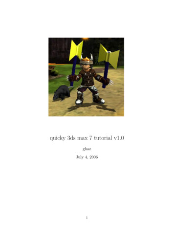
Figure 7: editable polyand click on Convert to Editable Poly. If you now go to the Modifysection on the top right of your screen you will no longer see the parametersof the cylinder. Now you will see Figure 7 (click on the little plus next toEditable Poly to see the detail). I only use the vertex and polygon options.A quick explanation might be necessary.A vertex is a point in space. The line connecting two vertices is called aedge. A polygon is a ‘surface’ surrounded by edges. My jargon might not betotally correct, so if my explanation is too vague, just click on vertex, edge orpolygon and select bits of your object. You will quickly learn what is what.Click on Polygon and select all the polygons as shown in Figure 8. Makesure the Ignore Backfacing box is NOT checked. If it is, you can only selectthe polys in the front. We now want to create the polys for the head. If youhaven’t realized yet, you can scroll down on the right menus. Scroll down until you get to the Edit Geometry section. Click on the Slice Plane button.A yellow line should appear. Click the move button at the top and moveit upwards until it looks like Figure 9. Note that when you click the movebutton, axes appear with the yellow line. If you hold the move cursor on thex -axis while moving, you will only move on the x -axis. The same applies fory and z. If you click on the top right corner of the square between the axes,you can move in any direction you can see in that specific view. Sometimesyou might want to switch to a different view to move a object. If the yellowline is in position, just click Slice (the button below the slice plane button).Now your object should look like Figure 10. You can see that we sliced thepolys into more polys.5
Figure 8: selecting polysNow select the new polys. Make sure you don’t select to poly at the top.Scroll around on the menu at the right and look for the Edit Polygons section. Click on the little settings box next to the Extrude button. Changethe type to Local Normal and the height to 2. Press OK. See Figure 11 fordetails and how the result should look.Now go to your front view and select the polys at the top-middle. Extrude them by 20. The result should look like Figure 12. Now we will shapethe blades.Change to vertex mode and look at your left view. Select the verticesin the corners as shown in Figure 13. Click and hold the scale button andselect non-uniform scale (see Figure 14). Click on the y-axis and move up.Scale until it looks like Figure 15. Scaling the vertices on the y-axis onlymoves them away from each other. You could have moved the vertices byhand, but this method ensures that the top and bottom vertices are exactlythe same distance from the middle.6
Figure 9: slice planeFigure 10: after slice7
Figure 11: extrudingFigure 12: extruding the blade8
Figure 13: selected verticesFigure 14: non-uniform scaleNow lets just sharpen the blades. Again select all the blade corner vertices. Click on the Weld settings box under the Edit Vertices section (seeFigure 16. Set the threshold to 7 and press OK. If the distance betweensome the selected vertices is less than 7, this will weld them together. Asyou can see, the vertices at the ends of the blades are now welded together.The blade is now sharp.This isn’t the prettiest axe ever, but it looks fine for a first try. Now letssee how it looks in Fate. I included a mod manager compatible example itemwith this. So lets just export the model to the correct folder. If you don’tknow how to add an item to Fate, check out some of the excellent tutorialson the Fate Modding Forum.To export, go to F ile Export. Select Screwdriver Model (*.MDL) as9
Figure 15: done with scalingFigure 16: weld10
the save type. If .MDL is not listed as a possibility, you need to get theplugins from the Mod Kit. Look for it on the Fate Modding Forum. Save itas MODS/quickytut/ITEMS/myaxe.mdl. Use the viewer.exe programthat comes with the Mod Kit to view the model. If it doesn’t show in theviewer, something is wrong. (Ignore the weird texture that shows up in theviewer. We still have to add a texture) Use Mod Manager to apply the modand enter the game. Press Ctrl-Shift- and type myaxe.If you did everything correct and you equipped the axe, you will see something like Figure 17. I like my axes big, but I think we can all agree thatit is a bit too much. So lets resize. Select the axe and click and hold scaleagain, but this time choose uniform scale. You can either click and drag toscale, or manually enter the value in the box at the bottom of the screen asdone in Figure 18. 4.5 gives a bit better result. Export and overwrite the oldfile in the mod folder. Run the game again and cheat the item. Looks betterthis time, but he doesn’t grip the handle exactly where I want. To changethis we move the pivot.Select the axe. Click on the Hierarchy tab (top-right corner, next to theModify tab). Click Affect Pivot Only and move the pivot to the desired position. The pivot shows where the object is positioned and which way it shouldface. So moving and rotating the pivot will result in a rotated or moved itemin Fate. The end moving result should look something like Figure 21. If youexport it again you will see the grip is now perfect (Figure 22).Now we only have to do the texture. This isn’t as easy as it sounds. Timeto save and backup.Select your object. Make sure you don’t just select polys or vertices, butthe object itself. Go the Modify tab and click on the words Modifier List(see Figure 23). Scroll down and select Unwrap UVW. It should be the exactwords, not something close to it. If your Modify window doesn’t look exactlylike Figure 24, right-click the Unwrap UVW and delete. Make sure you object is correctly selected and try again. The purpose of the UVW-thing is toget a flat representation of your model that you can color. The list containingour Edit Poly and Unwrap UVW is called the modifier stack. It should alsobe seen as a litteral stack. You should not try to modify anything that isnot on top. It could still work, but then again, why take the risk.11
Figure 17: too big :)Figure 18: uniform scale12
Figure 19: held too lowFigure 20: adjust pivot13
Figure 21: moved pivotFigure 22: perfect grip14
Figure 23: modifier listFigure 24: after clicking Unwrap UVWWith everything still selected, scroll down and click on the Planer Mapbutton and then on Edit. What you see now will hopefully confuse you. Itshould look something like Figure 25. Luckily we can make it better. In thisnew Edit UVWs window go to M apping F latten M apping and press OK.Usually it doesn’t turn out this nice, but this time we were lucky. Now itshould look sort of like Figure 26. As you can see there are no overlappinglines, so it should be quite easy to colour.The next step seems a bit crude, but it is the only way I know how. Still inthe Edit UVWs window, go to Options Advanced Options. Uncheck the15
Figure 25: huh?Figure 26: nice uvw map16
Figure 27: texture filethree boxes in the colors section. Now you should have a dark blue block withwhite lines showing the different polys. Zoom in until the dark blue blockfills the screen and press PrintScreen on your keyboard. Open your favouriteimage editing program (GIMP, Photoshop, paint). Go to Edit P aste.Select only the blue border with the image inside and go to Edit Copy.Paste it as a new image. Should look like a image with a blue border. Nowyou should just color it. For this I really recommend Photoshop or GIMP.If you don’t already have Photoshop, don’t bother buying it, use the GIMP(it is free). Remember to save in in the same folder as your 3ds Max file.I tried to finish my texture file as quickly as possible, so hopefully yourswill look better. Mine looks like like Figure 27. I really hope yours looksbetter. Now we have to apply the texture to the model.Close the Edit UVWs window. Select you object and press m. Selectthe top left material and click on the button that says Standard (see Figure 28). Double-click on Multi/Sub-Object. If it asks if you want to keepor discard old materials, I usually just discard, but if you added somethingpreviously it might be better to keep it. Now click on the topmost material.The material number doesn’t matter (yours will probably be different frommine), just pick the one next to id 1 (see Figure 29). Scroll down to Mapsand click on the box (labelled none) next to Diffuse Color. Double-click on17
Figure 28: materials windowbitmap and find myaxe.png. It should be in the same folder as your .maxfile. Now click the Assign Material to Selection button and click ShowMap in Viewport (see Figure 30). Click the Go to Parent button to goback to the main materials window. Your object should now be textured .but it is not. Unfortunately I made a mistake, so lets fix it. :)Close the materials window. What went wrong is that I forgot to give theobject a material ID. This is something that you are supposed to do beforeyou create the UVW map. We already spent a lot of time on the map andthe texture, so to redo it all will just be terrible. Luckily we don’t have to.Select your object and once again click on the Modifier List on the right.This time select Edit Poly. Now we can make changes to our poly withoutlosing the previous work. Choose polygon mode and select all the polys. Itshould look like Figure 31. Make sure that the Ignore Backfacing box is notchecked. Scroll down to the Polygon Properties section. Type 1 in the SetID box and press enter (see Figure 32).18
Figure 29: select the materialFigure 30: assigning the materialNow everything should work. If you want a nice rendered picture, pressF10, choose the viewport and click on Render. This is a good way to createan icon.OK, so export the model again and this time also copy myaxe.png to themod folder. Now the model in-game should look like Figure 33 (hopefullywith a better texture than mine).For the final bit we’ll make the blade shiny. This involves creating a reflection texture and assigning it to the model. Very easy. First make a copyof myaxe.png and rename it myaxeref.png. Open myaxeref.png in your image editor and get ready to edit. The reflection texture is a grayscale imagewhere black causes no reflection and white total reflection. I’m going to editmine so that the handle reflects nothing and the blade almost everything.The result looks like Figure 34.Press m again to go to the materials window. Again click on the materialnext to id 1. Scroll down to Maps and click on the button next to Reflection.Double-click on bitmap and find myaxeref.png. Press the Assign Material to19
Figure 31: selecting all the polysFigure 32: assigning material ids20
Figure 33: textured axeFigure 34: my reflection texture21
Selection button. For some strange reason the reflection map doesn’t workcorrectly when I render it in 3ds Max, but it works perfectly in Fate. So mymethod is probably wrong, but for Fate it works.Last step! Export the model again and remember to also copy myaxeref.pngto the mod folder. Run the game and play with your new axe.Enjoy the chopping.ghaz22
for me while also using as many different 3ds max stuff as possible. I also advise you to make a brand new save after each big step. That way you can . check out some of the excellent tutorials on the Fate Modding Forum. To export, go to File Export. Select Screwdriver Model (*.MD