Transcription
Autodesk 3ds Max Design 2012 FundamentalsSupplementalFilesSDCP U B L I C AT I O N SSchroff Development CorporationBetter Textbooks. Lower Prices.www.SDCpublications.comTutorial files onenclosed CD
Visit our website to learn more about this and other books:
Chapter 3Basic Modeling TechniquesThis chapter introduces:9Model with Primitives9Applying Transforms9Sub-Object Mode9Reference Coordinate Systems and Transform Centers9Cloning and Grouping9Poly Modeling with Graphite Tools9Statistics in Viewport3–1
3–2
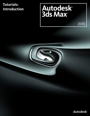
Basic Modeling Techniques3.1 Model with PrimitivesAutodesk 3ds Max Design software enables you to create andadjust 3D geometry by creating a complex model, as shown inFigure 3–1, from simple 3D objects called primitives.Figure 3–1 Not everyone works with Autodesk 3ds Max Design as theirprimary modeling tool. However, even for those who do not,modeling with Autodesk 3ds Max Design primitives might still beuseful for additional dressing or background objects to add to yourimported scenes. Modeling with primitives is only one approach to creating geometryin Autodesk 3ds Max Design. Other processes, such as modelingwith modifiers, creating loft compound objects or creating a 3Dterrain from 2D contour objects, can also be done. Do not duplicate.3–3
Autodesk 3ds Max Design 2012 FundamentalsPractice 3aModeling with PrimitivesEstimated time forcompletion: 10 minutes.In this practice you will model the base for the parking lot light fixtures.You will continue with this model in other practices.1. Open Modeling with Primitives.max from your Class Files folder.If you get a dialog box that mentions a File Load: Mismatch, clickto accept the default values.2. In the Command Panel, select the Create tab (). Click(Geometry) and verify Standard Primitives displays in thedrop-down list. In the Object Type rollout, click.3. If the Keyboard Entry rollout is collapsed, clickto expand it.4. In the Keyboard Entry rollout leave the X, Y, Z coordinates at 0’0”.Set the Radius to 1’0” and the Height to 3’0”. Click. Youcan either enter the values directly in the respective fields or usethe spinner arrows to increase or decrease the values.5. Click(Zoom Extents) to get a closer look at the base. Notethat it zooms into the cylinder in the Perspective viewport only,because that is the active viewport (yellow border).Note: After creating an object, you cannot change the parameters in theKeyboard Entry rollout. Changing the parameters in the Keyboard Entry rolloutand clickingadds a second object. If you created another object, inthe Quick Access Toolbar, clickonce to undo the creation of second object.) to change the parameters.After creating an object, use the Modify tab (Select the object if necessary, and select the Modify tab.Note: After entering a value in a field, either click in another edit field or press Enter to see its affect in the viewports.6. With the cylinder still selected, in the Command Panel, select theModify tab ( ). At the top of the modifier list, in the name field,rename the object from Cylinder001 to LP Base.3–4 Do not duplicate.
Basic Modeling Techniques7. In the Parameters rollout, set Radius to 1’6”. You can also set thenumber of segments and sides for the object. Try changing thesevalues to see what effect they have on the geometry. Set bothHeight Segments and Cap Segments to 1 (default) and Sides to20, as shown Figure 3–2.Figure 3–28. Select the Create tab () and in the Object Type rollout, clickto create the anchor base plate. In the Keyboard Entryrollout set X, Y, Z coordinates to 0’0”, 0’0”, 3’0”. Set the Lengthand Width to 1’4” and the Height to 0’2”. Click. A box iscreated on top of the Base cylinder, as shown in Figure 3–3.Figure 3–39. With the box selected, click the Modify tab (object as LP Anchor Base.10. Click Do not duplicate.) and rename the Save As and save your work as MyLight Pole.max.3–5
Autodesk 3ds Max Design 2012 Fundamentals3.2 Applying TransformsMany CAD and 3D graphic programs consider Move, Rotate, andScale as modify options similar to Stretch, Break, and Trim.However, in Autodesk 3ds Max Design there is a significant distinctionbetween modifiers and transforms. Modifiers add geometric and property alterations to objects. Theyare listed in the Modifier Stack and their parameter values areavailable for adjustment afterwards. Transforms are used to translate (move) and scale objects in thescene. The three Autodesk 3ds Max Design transforms are Move,Rotate, and Scale. Transforms are conducted by accessing atransform mode and typing new values or graphically transformingobjects on the screen. Transforms are applied to objects after basic parameters andmodifiers have been taken into account (except world-spacemodifiers). For example, if you scale a box, the Length parametershown in the Modifier Stack does not take into account the effectsof the scale transform. An object can have any number of modifiers, but only has a singleset of transform values at any time. Transforms and almost all object and modifier parameters can beanimated in Autodesk 3ds Max Design. For example, awalkthrough animation can be created using Move Transform tomove the camera or its target or both. Transform modes are initiated by selecting the required buttons inthe Main toolbar or by using the Transform modes in the right-clickquad menu.The Transform tools are:Select and MoveSelect and Rotate3–6 Do not duplicate.
Basic Modeling TechniquesSelect and Scale: Scaling has three flyout options,(Uniform),(Non-uniform), and(Squash).Non-uniform enables you to scale one or two axesindependently. Squash enables you to do the same, butscaling one or two axes applies a simultaneous oppositescaling to the other(s). The Scale transform gizmo also hasthe tools to do Non-uniform scaling.Hint: It is best not to use the Scale transform directly on objects. Instead, applyan XForm modifier to the objects and then Scale the XForm gizmo. This avoidsmany problems in animation, because you can define when the scale is takingplace at the sub-object level.Transforms can be constrained to one or two axes by selecting one ofthe buttons in the Axis Constraints toolbar, as shown in Figure 3–4.However, it is more common to use the gizmos or the keyboardshortcuts to constrain the transforms. This toolbar is hidden bydefault.Figure 3–4When a transform mode is active, a Transform gizmo displays, asshown in Figure 3–5, on the selected object on the screen. If theTransform gizmo is missing, press X to toggle it on.MoveRotateScaleFigure 3–5Clicking and dragging over the gizmo enables you to perform thetransform interactively on the screen. You can also constrain thetransform by highlighting an axis handle on the gizmo before clickingand dragging. Do not duplicate.3–7
Autodesk 3ds Max Design 2012 FundamentalsYou can apply a transform accurately by entering the requiredtransform values in the Transform Type-In area in the Status Bar, asshown in Figure 3–6.Figure 3–6You can also right-click on any of the Transform buttons to open aTransform Type-In dialog box, as shown in Figure 3–7 for the Movetransform.Figure 3–7The Transform Type-In dialog box can also be accessed byright-clicking the object and clicking(Settings) to the right of Move,Rotate, or Scale, as shown in Figure 3–8.Figure 3–8Transform modes remain active until they are canceled. One way tocancel a transform mode is by clicking(Select Object) in theMain toolbar or pressing Q . You should consider selecting Selectafter you have finished a transform to avoid accidentally moving,rotating, or scaling objects while making selections.3–8 Do not duplicate.
Basic Modeling TechniquesPractice 3bModeling with Modifiers andTransformsEstimated time forcompletion: 20-30minutes.In this practice you will refine the parking lot lighting fixture withModifiers, then use Transforms to locate objects in the correct scenepositions.Task 1 - Extrude and Adjust the Light Pole.To create the rectangular light pole, create a 2D cross-section shapeand then extrude it into a 3D object. This approach is another way tocreate 3D geometry.1. Continue working with the file created in the previous practice,MyLightPole.max. If you did not complete it, open Modeling withModifiers and Transforms.max from your Class Files folder.2. In the Create tab (), click(Shapes) to create 2D objects.Verify that the Splines sub-category is displayed and click, as shown in Figure 3–9.Figure 3–93. In the Keyboard Entry rollout set X, Y, and Z to 0’0”, 0’0”, and3’2”. Set Length and Width to 0’6” each and set Corner Radius to0’1”. Click Do not duplicate.3–9
Autodesk 3ds Max Design 2012 Fundamentals4. A 2D rectangle is created on the top of base plate. With therectangle still selected, open the Modify tab ( ). Open theModifier List by clicking the down arrow next to it. In the ModifierList drop-down list, select Extrude. Note that Extrude gets listed inthe Modifier Stack, as shown in Figure 3–10.Figure 3–105. In the Parameters rollout, set Amount to 15’0” and leave the otherparameters at their default settings.6. Rename the object Rectangle001 as LP Pole.7. Use(Zoom) to get a closer look at the light pole, as shown inFigure 3–11. Note how much detail the light pole’s fillet adds to themodel.Figure 3–11Note: You should cut down on any unnecessary detail if the object is meant to bea background item and not the main focus of the visualization. Keeping modelssimple reduces the file size and speeds up software performance and renderingtimes.3–10 Do not duplicate.
Basic Modeling Techniques The Extrude modifier is listed directly above the Rectangle objectin the Modifier Stack. The rectangle’s parameters are stillaccessible and can be changed after the extrude is added.8. In the Modify tab ( ), in the Modifier Stack, select Rectangle. itgets highlighted in dark gray. In the Interpolation rollout changeSteps to 2 and press Enter . The fillet divisions are reduced, asshown in Figure 3–12. (In your projects you might change theSteps to 0 or not use fillets at all, if the object is not a focal point ofthe visualization.)9. Save your work as MyLightPole01.max.Figure 3–12Task 2 - Taper the Light Pole.The modifiers in theModifier drop-down listare placed in groups andthen listed alphabetically.Click and drag the scrollbar on the right of theModifier drop-down list todisplay the modifiers atthe bottom of the list.1. In the Modifier Stack, select Extrude (so that the next modifierTaper is applied after the Extrude). In the Modifier List, selectTaper, located at the bottom of this list. Note that the Taperdisplays above the Extrude in the Modifier Stack. The ModifierStack lists modifiers in reverse historical order.2. In the Taper area of the Parameters rollout, set Amount to -0.5,which relates to approximately a 50% size reduction over theheight of the object. Press Enter . You can still adjust the originalRectangle and Extrude parameters in the Modifier Stack.3. Click(Zoom Extents All) to see all the objects in the viewport.Note the taper on the pole towards the top.4. Click Save As. In the Save File As dialog box, clickautomatically save your work incrementally asMyLightPole02.max. Do not duplicate.to3–11
Autodesk 3ds Max Design 2012 FundamentalsTask 3 - Create the Fixture Housing and Globe.Previously you created primitives by keying in exact values in theKeyboard Entry rollout. Now you will roughly size the primitive shapesby clicking and dragging with the mouse in the viewport.1. In the Create tab (), click(Geometry). In the StandardPrimitives drop-down list, select Extended Primitives as asub-category. In the Object Type rollout, click.2. Next to the base (LP Base), click and drag the left mouse button tosize the radius to roughly 2’0” (Keep looking in the Parametersrollout in the Command Panel where the Radius changesinteractively as you move your mouse). After releasing the mousebutton, move your cursor up the screen slightly to give the cylindera height of approximately 1’0”. Click a second time to set thecylinder height. Then move the cursor up and down the screenuntil you can roughly define a 0’2” fillet. Complete the objectcreation process with a third click. The object should display asshown in Figure 3–13.Figure 3–13 All primitives can be sized by clicks and drags as you did here.You can enter the parameters of the object before creating it oryou can sketch in an object this way and fix its dimensions andposition after creating it.3. With the object, ChamferCyl, still selected, in the CommandPanel, select the Modify tab (shown in Figure 3–14.) and modify the parameters, as3–12 Do not duplicate.
Basic Modeling TechniquesFigure 3–144. Name the object LP Fixture Housing.5. In the Create tab (), click(Geometry). In the drop-down list,select Standard Primitives as a sub-category. In the Object Typerollout, clickto create the fixture’s globe. Click and draganywhere on the screen to size a sphere of approximately 1’0” inradius. Select the Modify tab ( ) and assign the parameters, asshown in Figure 3–15. Note the effects that each of them has onthe model, specifically the Hemisphere and Smooth values.Figure 3–156. Select the Squash option in the rollout. This option generatesmore faces and creates a smoother appearance. Since the globeis often where the viewer’s attention will be focused when lookingat the light pole, you should make it look as good as possible whilekeeping the polygon count low.7. Rename the hemisphere LP Fixture Globe.8. Click Save As and clickto automatically save yourwork incrementally as MyLightPole03.max. Do not duplicate.3–13
Autodesk 3ds Max Design 2012 FundamentalsTask 4 - Use Transforms to Position Objects.To complete this practice you will rotate and move the light polefixture housing and globe into position.1. Select the LP Fixture Housing (the chamfered cylinder) and inthe Main toolbar, click(Select and Move).2. In the Main toolbar, set the Reference Coordinate System toWorld by selecting it from the drop-down list and clickPivot Point Center), as shown in Figure 3–16.(UseFigure 3–16If the Transform gizmo ismissing, press X totoggle it on.3. The Move gizmo displays over the object, as shown inFigure 3–17. Move the fixture housing by clicking and dragging thegizmo’s axis handles and plane handles, noting how eachconstrains the movement to a certain axis or plane. By default, thegizmo displays at the object’s pivot point.Figure 3–174. To position the object precisely, use the Transform Type-Incontrols located in the Status Bar at the bottom of your screen.5. Verify that(Absolute Mode Transform Type-In) is displayed inthe Status Bar. The Absolute Mode button toggles with(Offset Mode). Theshould display.(Absolute Mode Transform Type-In)3–14 Do not duplicate.
Basic Modeling Techniques If the values are entered in Offset Mode, they are added to thecurrent coordinates. Offset Mode is useful if you want to move anobject a certain distance but are not sure what the resultingcoordinates will be.6. Set X to 0’0”, Y to -6’0”, and Z to 19’0”, as shown in Figure 3–18,and press Enter .Figure 3–187. As the Move transform and Absolute Mode are already active,select LP Fixture Globe (hemisphere) and enter the same X, Y, Zcoordinates. The globe moves inside the fixture housing.8. With the globe still selected, in the Main toolbar, clickand Rotate).(Select9. The X, Y, Z Transform Type-In fields display the current rotationswhich are 0. Set X to180 and note the position of the globe isinverted. The object should display as shown in Figure 3–19.Figure 3–1910. Click(Select Object) to end the Rotate transform as aprecaution to avoid rotating objects accidentally.11. Click Save As and clickto automatically save yourwork incrementally as MyLightPole04.max. Do not duplicate.3–15
Autodesk 3ds Max Design 2012 Fundamentals3.3 Sub-Object ModeMany of the objects and modifiers in Autodesk 3ds Max Designcontain sub-objects that can be independently adjusted throughtransforms and special modifier controls.These sub-objects are adjusted through a special Autodesk 3ds MaxDesign state called Sub-object mode. For example, the Tapermodifier in the column has Gizmo and Center sub-objects, as shownin Figure 3–20, that can be adjusted to position the Taper.Figure 3–20Working inSub-ObjectModeSub-object mode is activated through the Modifier Stack. You canexpand the modifier by clicking next to the name of an object ormodifier that has sub-objects, then clicking sub-object level to beadjusted. You normally can have only a single object selected to enter theSub-object mode. When Sub-object mode is active, the Sub-object level (or themodifier name if the Sub-object list has not been expanded) ishighlighted in yellow (with the default user interface settings). Normally you cannot clear the currently selected object while inSub-object mode. Therefore, to edit another object you must firstexit Sub-object mode. To do so, select the level of the ModifierStack presently highlighted in yellow, or select the name of themodifier where you are in Sub-object mode.3–16 Do not duplicate.
Basic Modeling Techniques If you see your Modifier Stack highlighted in yellow accidentally,(where you did not intend to be in Sub-object mode) simply selectthe yellow highlighted item to exit the mode.GeometricEdits throughSub-objectsA whole range of explicit geometric changes can be made throughSub-object mode. Objects imported into Autodesk 3ds Max Design often take theshape of Editable Splines or Editable Meshes. These haveSub-object controls that can be edited directly. For example, agroup of vertices in an Editable Mesh could be selected andmoved, or deleted separate from the rest of the geometry. Many Autodesk 3ds Max Design objects can also have thesecontrols applied to them through an Edit Spline modifier (for 2Dobjects) or an Edit Mesh or Edit Poly modifier (for 3D objects).This includes geometry linked to AutoCAD drawings that list onlyas Linked Geometry in the Modify tab. Figure 3–21 shows a Box that is being edited geometrically bylowering two of its vertices with the Move transform.Figure 3–21 The Edit Mesh modifier is best for objects based on a triangularmesh, such as triangulated terrain models. The Edit Poly modifieris best for objects with faces of more than three vertices, such asrectangular objects. In general it is best to adjust objects through their core parameters(such as the length, width, and height of a Box primitive) andstandard modifiers whenever possible. This makes it easier toreview the changes and adjust them. For cases where this is notpossible, Spline, Mesh, and Poly editing can be an effectivealternative. Do not duplicate.3–17
Autodesk 3ds Max Design 2012 FundamentalsGeometricSub-ObjectsThe Editable Spline, Editable Mesh, and Editable Poly objects (as wellas any other object with an Edit Spline, Edit Mesh, or Edit PolyModifier applied to it) share a number of common Sub-object modes.These are:Vertex: The individual 3D points that define an object (EditSpline, Edit Mesh, or Edit Poly).Segment: A single line or curve segment of an EditableSpline.Spline: A series of one or more connected Editable Splinesegments. Segments are considered connected if they sharea common vertex.Edge: The linear segments connecting vertices with EditMesh or Edit Poly. Three edges are shown in the button.Face: The triangular surface area defined by three edges(Edit Mesh only).Border: A series of edges that define an opening in anEditable Poly (only).Polygon: Enables you to work with coplanar faces (EditMesh) or a defined polygon (Edit Poly).Element: Enables you to work with all the faces or polygonsthat form a contiguous whole (Edit Mesh or Edit Poly).SmoothingOne of the most important properties controlled at the face or polygonsub-object level is smoothing. Figure 3–22 shows the same geometrywith and without smoothing applied.Figure 3–22 Autodesk 3ds Max Design can have two adjacent faces appear tobe smooth or faceted. This distinction becomes very importantwhen dealing with curved or gently undulating objects. Whensmoothed, faces appear smooth but Autodesk 3ds Max Designdoes not adjust the actual geometry.3–18 Do not duplicate.
Basic Modeling Techniques Smoothing is controlled by smoothing groups. Each face orpolygon can be a member of up to 32 smoothing groups. If twoadjacent faces share a common smoothing group, Autodesk 3dsMax Design attempts to blend the surfaces together to disguisethe edge that separates them. As an example of the controls for polygon smoothing groups (inEdit Mesh and Edit Poly), Figure 3–23 indicates the smoothinggroups for the selected faces. When some but not all selectedfaces fall into a particular smoothing group, that group’s box isshown without a number.Figure 3–23As an alternative to manually assigning smoothing groups there is anAuto Smooth feature. This feature automatically places adjacentselected faces into smoothing groups if their normal vectors have anangle of separation equal to or less than the Auto Smooth angle.(Normals are formally described in the rendering material).Note: You can also use the Graphite Modeling Tools located in the ModelingRibbon, to perform modeling with Edit Poly techniques. Do not duplicate.3–19
Autodesk 3ds Max Design 2012 FundamentalsPractice 3cModeling with Edit Poly inSub-Object ModeEstimated time forcompletion: 10 minutes.In this practice you will add some detail to the concrete base of thelight pole by chamfering (beveling) the outside top of the cylinder.1. Continue with the file created in the previous practiceMyLightPole04.max. If you did not complete it, open Modelingwith Edit Poly in Sub-Object Mode.max from your Class Filesfolder.2. Select LP Base and click(Zoom Extents Selected).3. In the Modify tab ( ), select Edit Poly from the Modifier List.Click for Edit Poly and select Polygon to activate Sub-objectmode at the Polygon level. The yellow highlighting in the ModifierStack indicates that you are now in Sub-object mode, as shown inFigure 3–24.Figure 3–243–20 Do not duplicate.
Basic Modeling TechniquesNote: You can also perform all the commands through the Graphite ModelingTools located in the Modeling Ribbon. With the object selected, select PolygonModeling tab under the Graphite modeling tools. In the drop-down list, select theApply Edit Poly Mod, as shown in Figure 3–25. Clickfor Polygonsub-object level. Note that the selections that you make in the Ribbon (GraphiteModeling Tools) are reflected in the Command Panel and vice versa.Figure 3–254. Select the polygon at the top of the cylinder, as shown inFigure 3–26.Figure 3–26Note: Creating a 1” bevel will raise the cylinder top by 1”. In preparation you willfirst lower the top of the cylinder by that same 1”.5. In the Main toolbar, clickmove gizmo is displayed. Do not duplicate.(Select and Move). Note that the3–21
Autodesk 3ds Max Design 2012 Fundamentals6. In the Status Bar, click(Absolute Mode Transform) to changeinto(Offset Mode Transform) and set Z to -0’1” and press Enter . The cylinder geometry is adjusted.7. In the Command Panel, in the Edit Polygons rollout, next to, click (Settings), as shown in Figure 3–27. You mighthave to scroll down to locate this rollout.Figure 3–278. The heads-up display opens on the screen. In the heads-updisplay, setHeight of 0’1” and anas shown in Figure 3–28. ClickOutline Amount of -0’1”,.Figure 3–28 The base is beveled as shown in Figure 3–29.Figure 3–293–22 Do not duplicate.
Basic Modeling Techniques9. To make the newly created faces smooth you will adjust thesmoothing groups. While still in Polygon sub-object mode, in thepull-down menu, select Edit Select All. In the Command Panel,in the Polygon: Smoothing Groups rollout, clicktoremove the existing smoothing. Set the AutoSmooth angle to 30,as shown in Figure 3–30, and click.Figure 3–3010. To better see the effect of this change, turn off the Edged Faces inthe Viewport Shading label, if enabled. The angle of 30 degreesenabled the newly created faces to smooth across each other, butthose faces are not smoothed with the top of the cylinder, asshown in Figure 3–31. This is the chamfered appearance that wasoriginally intended. A larger smoothing angle enables thechamfered faces between the top and sides to smooth out.Figure 3–3111. To end Sub-object mode, in the Command Panel Modifier Stack,click on the yellow highlighted Polygon to clear the selection. Thetop Modifier Edit Poly is highlighted as dark gray.12. In the Main toolbar, click(Select Object) to end the MoveTransform mode as a precaution to avoid moving objectsaccidentally while making further selections.13. Save your work as MyLightPole05.max or usedialog box if using the MyLightPole04.max file. Do not duplicate.in the Save As3–23
Autodesk 3ds Max Design 2012 Fundamentals3.4 Reference Coordinate Systemsand Transform CentersAll geometry in Autodesk 3ds Max Design is referenced to a basecoordinate system called the Home Grid. You can create your own coordinate systems by creating andlocating grid objects, available in the Helpers Category in theCreate tab. User Coordinate Systems created in AutoCAD can automaticallybe brought into Autodesk 3ds Max Design as grid objects. You can also create objects in AutoGrid mode, which creates atemporary Grid aligned in 3D to the object directly under thecrosshairs. The option to enable AutoGrid is located in the Createtab, in the Object Type rollout, as shown Figure 3–32 (AutoGrid issimilar to the Dynamic UCS feature introduced in AutoCAD 2007).If you hold down Alt , the AutoGrid remains available for futureuse. If you use AutoGrid without any key pressed, the griddisappears after object creation.Figure 3–32ReferenceCoordinateSystemsAlthough a single grid is active at any one time, the current ReferenceCoordinate System might differ depending on which view you are inand which transform is active. It is recommended that new users stayin the World system as much as possible to avoid confusion fromchanging axis labels. The Default Reference Coordinate system is setto View.3–24 Do not duplicate.
Basic Modeling Techniques In the Main toolbar, the options listed in the Reference CoordinateSystem drop-down list, as shown Figure 3–33, controls howtransform values are read.Figure 3–33 In the World coordinate system the X, Y, and Z axes areinterpreted based on the Home Grid, even if a user-defined grid isactive. To use the coordinates of the active user-defined gridinstead, select the Grid option. In the Screen coordinate system the X-axis is always measuredalong the bottom of the viewport, the Y-axis is always measuredalong the side, and the Z-axis is measured perpendicularly out ofthe screen. For example, in a front view using the Screenreference system the Y-axis is measured “up” the screen. Thatsame view in the World system would measure Z-axis “up” thescreen instead. The View system is a combination of World and Screen. In anorthographic view the Screen system is used, while other viewsuse the World system. The Pick option enables you to pick any object in the viewport orfrom a list and use the reference coordinate system of that objectas the reference for transforms. You can use XRef objects with thePick option. The Working option enables you to use the Working Pivot. It is atemporary modeling pivot tool you create from the Hierarchypanel’s Pivot tab. Generally you need to assign a hotkey to UseWorking Pivot and Edit Working Pivot to make them functionaltools. Do not duplicate.3–25
Autodesk 3ds Max Design 2012 FundamentalsTransformCentersTransforms are applied through a Transform Center point indicated bythe Transform Gizmo. There are three options for the TransformCenter and can be accessed in the Main toolbar, in the TransformCenter flyout, as shown Figure 3–34.Figure 3–34Pivot Point Center: Transforms are applied through eachselected object’s pivot point. Pivots often default to the bottomcenter or geometric center of objects. Pivot points can beadjusted through controls in the Hierarchy tab. Select thisoption if you want to rotate many objects, each around its owncenter.Selection Center: Transforms are applied through thegeometric center of all selected objects.Tr
Autodesk 3ds Max Design software enables you to create and adjust 3D geometry by creating a complex model, as shown in Figure 3–1, from simple 3D objects called primitives. Figure 3–1 Not everyone works with Autodesk 3ds Max Design as their p