Transcription
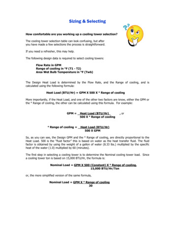
Sizing & SelectingHow comfortable are you working up a cooling tower selection?The cooling tower selection table can look confusing, but afteryou have made a few selections the process is straightforward.If you need a refresher, this may help.The following design data is required to select cooling towers:Flow Rate in GPMRange of cooling in F (T1 - T2)Area Wet Bulb Temperature in F (Twb)The Design Heat Load is determined by the Flow Rate, and the Range of cooling, and iscalculated using the following formula:Heat Load (BTU/Hr) GPM X 500 X Range of coolingMore importantly, if the Heat Load, and one of the other two factors are know, either the GPM orthe Range of cooling, the other can be calculated using this formula. For example:GPM Range of cooling Heat Load (BTU/Hr)500 X Range of cooling, orHeat Load (BTU/Hr)500 X GPMSo, as you can see, the Design GPM and the Range of cooling, are directly proportional to theHeat Load. 500 is the “fluid factor” this is based on water as the heat transfer fluid. The fluidfactor is obtained by using the weight of a gallon of water (8.33 lbs.) multiplied by the specificheat of the water (1.0) multiplied by 60 (minutes).The first step in selecting a cooling tower is to determine the Nominal cooling tower load. Sincea cooling tower ton is based on 15,000 BTU/Hr, the formula is:Nominal Load GPM X 500 (Constant) X Range of cooling,15,000 BTU/Hr/Tonor, the more simplified version of the same formula,Nominal Load GPM X Range of cooling30
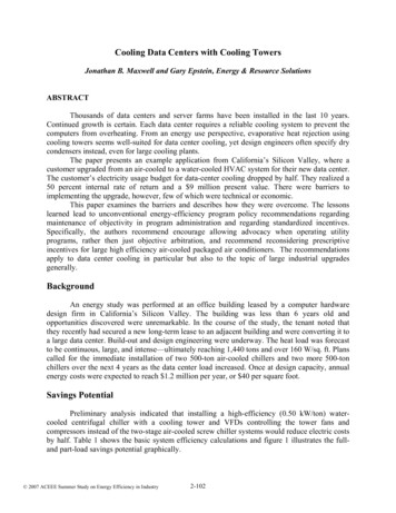
Sizing & SelectingOnce the Nominal cooling load has been calculated, a Correction Factor must be determined tocalculate the Actual Rated cooling tower tons required for the specific conditions of service. Thecorrection factor adjusts for the ease or difficulty of cooling based on the Theoretical Design of allcooling towers.The Nominal Ton Correction Factor is determined byusingtheCOUNTERFLOWCOOLINGTOWERSELECTION AND PERFORMANCE CHART enclosed.Note that the curves are shown as three separatesections. The WET BULB CORRECTION SECTION, theAPPROACH SECTION and the CAPACITY MULTIPLIERFACTOR SECTION.First find Range line in the WET BULB CORRECTIONSECTION in the upper left-hand section of chart. Movealong the Range line over to the intersection of theWet Bulb line.Now move down along the Wet Bulb line to theAPPROACH SECTION, in the lower left-hand section of the chart, and stop at the intersection ofthe Approach line.Move across to the CAPACITY MULTIPLIER FACTOR SECTION to the right-hand curves and stopat the intersection of the Range line and read the CAPACITY MULTIPLIER FACTOR.The Actual Rated cooling tower tons can now be calculated by multiplying the Nominal coolingtons, which was previously calculated, by the CAPACITY MULTIPLIER FACTOR.The Actual Rated cooling tower tons is the capacity required for the specific conditions of service,and the next largest size cooling tower should be selected for the application.Following are selection examples for three different applications. One example is based onconditions which are identified as "Theoretical Design", for reasons which will becomeapparent.The second example, entitled "Actual Design" is a selection based on adjusting fromTheoretical to Actual design.The third example, "Modified Application", converts an actual once through well water systemto a cooling tower recirculation system.
Sizing & SelectingCooling Tower Selection ProcedureExample 1. Theoretical DesignThe following conditions are provided for selection purposes:The operating water flow rate is 600 gpm.Hot water temperature (T1) to the cooling tower is 95 F.Cold water temperature (T2) desired from the cooling tower is 85 F.The installation location wet bulb temperature (Twb) is 78 F.You can now make a cooling tower selection with this information:The water flow is 600 gpm.The Range of cooling is 10 - (T1 - T2)The Approach to the wet bulb temperature is 7 - (T2 - Twb)First the cooling tower NOMINAL load has to be determined:Nominal Load GPM x 500 x Range, GPM x Range,15,000 BTU/Hr30therefore,Nominal Load 600 gpm x 10 Range 200 tons of cooling required.30Since the Heat Load Flow (gpm) x 500 x Range of cooling 600 gpm x 500 x 10 3,000,000 BTU/Hrand a cooling tower nominal ton 15,000 BTU/Hr, the nominal cooling tower ton is derived fromthe actual heat load. Therefore,a heat load of 3,000,000 BTU/Hr 200 nominal cooling tower tons.Now the Nominal Ton Correction Factor has to be determined for the conditions established; a10 Range of cooling, and a 7 Approach to the design wet bulb temperature of 78 F, using theCOUNTERFLOW COOLING TOWER SELECTION AND PERFORMANCE CHART enclosed.Find the 10 Range line in the WET BULB CORRECTION SECTION in the upper left-hand sectionof the chart. Move along the 10 Range line over to the intersection of the 78 Wet Bulb line.Move down along the 78 Wet Bulb line to the APPROACH SECTION, (the lower left-handsection), and stop at the intersection of the 7 Approach line. Move across to the CAPACITYMULTIPLIER FACTOR SECTION to the right-hand curve and stop at the intersection of the 10 Range line, and read the CAPACITY MULTIPLIER FACTOR, which is 1.0.To select the proper cooling tower for this application, multiply the 200 Nominal tons calculated,by the 1.0 CAPACITY FACTOR. As previously stated, the correction factor adjusts for the ease ordifficultly of cooling in relation to Theoretical Design. So in this case, since the CAPACITYCORRECTION FACTOR is 1.0, the Nominal and Actual Rated tons are the same as the TheoreticalDesign, and a Model DT-200I cooling tower can be quoted.
Sizing & SelectingCooling Tower Selection ProcedureExample 2. Actual DesignNow we will select a cooling tower for the same 200-ton Nominal Load as Example #1 but isdifferent from the Theoretical Design.The operating water flow rate is 300 gpm.Hot water temperature (T1) to the cooling tower is 105 F.Cold water temperature (T2) desired from the cooling tower is 85 F.The installation location wet bulb temperature (Twb)is 76 F.You can now make a cooling tower selection with this information:The water flow is 300 gpm.The Range of cooling is 20 - (T1 - T2)The Approach to the wet bulb temperature is 9 - (T2 - Twb)First the cooling tower NOMINAL load must be determined:Nominal Load GPM x 500 x Range, GPM x Range;15,000 BTU/Hr30therefore,Nominal Load 300 gpm x 20 Range 200 cooling tons required.30Since the Heat Load Flow (gpm) x 500 x Range of cooling 300 gpm x 500 x 20 3,000,000 BTU/Hrand a cooling tower nominal ton 15,000 BTU/Hr, the Nominal cooling tower ton is derived fromthe actual Heat Load. Again, a 3,000,000 BTU/Hr heat load 200 Nominal cooling tower tons.Now the Nominal Ton Correction Factor must be determined for the conditions established; a 20 Range of cooling, and a 9 Approach to the design wet bulb temperature of 76 F, using theCOUNTERFLOW COOLING TOWER SELECTION AND PERFORMANCE CHART enclosed.First find the 20 Range line in the WET BULB CORRECTION SECTION in the upper left-handsection of chart. Move along the 20 Range line over to the intersection of the 76 Wet Bulb line.Move down along the 76 Wet Bulb line to the APPROACH SECTION, in the lower left-handsection of the chart, and stop at the intersection of the 9 Approach line. Move across to theCAPACITY MULTIPLIER FACTOR SECTION to the right-hand curves and stop at the intersectionof the 20 Range line, and read the CAPACITY MULTIPLIER FACTOR, which in this case is 0.62.The final step to select the proper cooling tower for this application is to multiply the 200 nominalcooling tons required, which was calculated above, by the CAPACITY FACTOR, which in this caseis 0.62. The cooling tower Actual Rated tons for the conditions given is therefore 124 tons, and aModel DT-125I cooling tower can be quoted. Since the correction factor adjusts for the ease ordifficulty of cooling based on the Theoretical Design, in this case, the Actual Rated towerconditions are easier than Theoretical Design.
Sizing & SelectingCooling Tower Selection Procedure3. Modified ApplicationThe following is an example of modifying a "once through non-recirculating cooling application"to a recirculating cooling tower system.A cooling tower is required for heat exchanger process cooling, which is now being cooled using55 F well water at a flow rate of (1 Million gallons/day - 300,000 sanitary 700,000 gal per day)Approximately 500 gpm, and discharging to a lake at 80 F.With this information we can establish the Heat Load, which is500 gpm x 500 x 25 R (80 F - 55 F) 6,250,000 Btu/HrWe can establish the cooling tower design for a 6,250,000 Btu/Hr Heat Load, based on theinstallation location design Twb, which, for this example we'll say is determined to be 76 F, andby establishing a reasonable cold water temperature at a 7 Approach to the Twb, at 83 F.What we have to determine now is either the design range of cooling, or the appropriate designflow rate based on the established Heat Load.Lets select the appropriate design flow rate by using a reasonable 15 Range of cooling; 83 Fcold water 15 98 F hot water.Use the Heat Load Formula to find the design flow rate as follows:Heat Load (BTU/Hr) GPM X 500 X Range of cooling,or rearranged to determine the design flow rate.GPM Heat Load (BTU/Hr)500 X Range of cooling 6,250,000 Btu/Hr500 x 15 R 835 gpmNow you can make your cooling tower selection based on 835 gpm, cooling from 98 F to 83 F @a design 76 F Twb. The cooling tower selection is 418 Nominal Tons x .83 DCF 347 Ratedcooling tower tons, or a 350-ton cooling tower selection.Alternate #1:A cooling tower can also be selected for this heat load based on a 25 Range of cooling. Theconditions for selection would be 500 gpm, cooling from 108 F to 83 F @ 76 F Twb, which isequal to 418 Nominal tons x .62 DCF 259 Rated cooling tower tons, for a 260 ton cooling towerrequirement.Alternate #2:Or select for a design to cool 110 F to 83 F 27 R of cooling, the design flow would be6,250,000 Btu/Hr 465 gpm.27 R x 500The selection for 465 gpm cooling from 110 F to 83 F @ 76 F Twb 418 Nominal tons x .58DCF 242 Rated tons; so you can recommend a single Model DT-250I cooling tower.
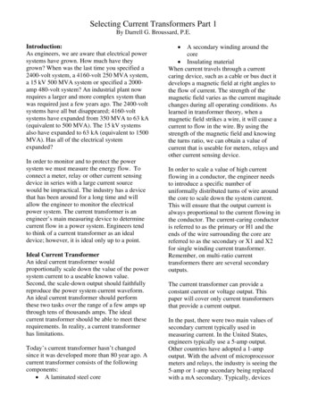
Sizing & SelectingCooling Tower Selection ProcedureOur “TowerSelect” software is available on our website izingThe program requires the input of the required flow rate, hot water temperature, cold-watertemperature, and the design web bulb temperature. The program will then calculate the Deltatower model for the given design conditions.
Choose the Delta model that has a capacity equal or greater to the corrected tons calculated.
The first step in selecting a cooling tower is to determine the Nominal cooling tower load. Since a cooling tower ton is based on 15,000 BTU/Hr, the formula is: Nominal Load GPM X 500 (Constant) X Range of co oling, 15,000 BTU/Hr/Ton . or, the more simplified version of the same formula, Nominal Load GPM X Range of cooling 30