Transcription
ME8651 Design of Transmission Systems Notes, Depart. of Mech. Engg. VTHT, AVADI, Chennai-62DESIGN OF TRANSMISSIONSYSTEMSNotesSubj. Code: ME8651For Third year Sixth Semester Mechanical StudentsPREPARED BYDr. P. NagasankarProfessor / Mechanical & Dean (S&H),Department of Mechanical Engineering,Vel Tech High Tech Dr Rangarajan Dr SakunthalaEngineering College,Avadi, Chennai-6000621
ME8651 Design of Transmission Systems Notes, Depart. of Mech. Engg. VTHT, AVADI, Chennai-62DEPARTMENT OF MECHANICAL ENGINEERINGSIXTH SEMESTER / III YEARME8651 DESIGN OF TRANSMISSION SYSTEMSLTPC3003OBJECTIVES:To gain knowledge on the principles and procedure for the design of Mechanical powerTransmission components.To understand the standard procedure available for Design of Transmission ofMechanical elementsTo learn to use standard data and catalogues (Use of P S G Design Data Book permitted)UNIT IDESIGN OF FLEXIBLE ELEMENTS9Design of Flat belts and pulleys - Selection of V belts and pulleys – Selection of hoisting wireropes and pulleys – Design of Transmission chains and Sprockets.UNIT IISPUR GEARS AND PARALLEL AXIS HELICAL GEARS9Speed ratios and number of teeth-Force analysis -Tooth stresses - Dynamic effects – Fatiguestrength- Factor of safety - Gear materials – Design of straight tooth spur & helical gearsbased on strength and wear considerations – Pressure angle in the normal and transverseplane- Equivalent number of teeth-forces for helical gears.UNIT IIIBEVEL, WORM AND CROSS HELICAL GEARS9Straight bevel gear: Tooth terminology, tooth forces and stresses, equivalent number of teeth.Estimating the dimensions of pair of straight bevel gears. Worm Gear: Merits and demeritsterminology. Thermal capacity, materials-forces and stresses, efficiency, estimating the sizeof the worm gear pair. Cross helical: Terminology-helix angles-Estimating the size of the pairof cross helical gears.UNIT IVGEAR BOXES9Geometric progression - Standard step ratio - Ray diagram, kinematics layout -Design ofsliding mesh gear box - Design of multi speed gear box for machine tool applications Constant mesh gear box - Speed reducer unit. – Variable speed gear box, Fluid Couplings,Torque Converters for automotive applications.UNIT VCAMS, CLUTCHES AND BRAKES9Cam Design: Types-pressure angle and under cutting base circle determination-forces andsurface stresses. Design of plate clutches –axial clutches-cone clutches-internal expandingrim clutches- Electromagnetic clutches. Band and Block brakes - external shoe brakes –Internal expanding shoe brake.TOTAL : 45 PERIODSOUTCOMES: Upon completion of this course, the students can able to successfully design transmissioncomponents used in Engine and machines2
ME8651 Design of Transmission Systems Notes, Depart. of Mech. Engg. VTHT, AVADI, Chennai-62TEXT BOOKS:1. Bhandari V, “Design of Machine Elements”, 3rd Edition, Tata McGraw-Hill Book Co,2010.2. Joseph Shigley, Charles Mischke, Richard Budynas and Keith Nisbett “MechanicalEngineering Design”, 8th Edition, Tata McGraw-Hill, 2008.REFERENCES:1. Sundararajamoorthy T. V, Shanmugam .N, “Machine Design”, Anuradha Publications,Chennai, 2003.2. Gitin Maitra, L. Prasad “Hand book of Mechanical Design”, 2nd Edition, Tata McGrawHill, 2001.3. Prabhu. T.J., “Design of Transmission Elements”, Mani Offset, Chennai, 2000.4. C.S.Sharma, Kamlesh Purohit, “Design of Machine Elements”, Prentice Hall of India,Pvt. Ltd., 2003.5. Bernard Hamrock, Steven Schmid, Bo Jacobson, “Fundamentals of Machine Elements”,2nd Edition, Tata McGraw-Hill Book Co., 2006.6. Robert C. Juvinall and Kurt M. Marshek, “Fundamentals of Machine Design”, 4thEdition, Wiley, 20057. Alfred Hall, Halowenko, A and Laughlin, H., “Machine Design”, Tata McGraw-HillBookCo.(Schaum‟s Outline), 20108. Orthwein W, “Machine Component Design”, Jaico Publishing Co, 2003.9. Ansel Ugural, “Mechanical Design – An Integral Approach", 1st Edition, Tata McGrawHill Book Co, 2003.10. Merhyle F. Spotts, Terry E. Shoup and Lee E. Hornberger, “Design of MachineElements” 8th Edition, Printice Hall, 2003.11. U.C.Jindal : Machine Design, "Design of Transmission System", Dorling Kindersley,20103
ME8651 Design of Transmission Systems Notes, Depart. of Mech. Engg. VTHT, AVADI, Chennai-62UNIT IDESIGN OF FLEXIBLE ELEMENTSCharacteristics of Belt DrivesS.No Characteristics1.2.3.4.5.6.7.8.Maximum velocity ratioMaximum belt speed (m/s)SlipTensionShock resistanceResistance to wearDressingInitial costFlat belts V- belts1635 to 1101 to 5%HighGoodGoodRequiredLessToothed or timingbelts121125801 to 5%NilLessVery lessGoodFairFairGoodNot Required Not RequiredLessModerateSELECTION OF A BELT DRIVESelection of a belt drive depends upon: Power to be transmitted Speed of driver and driven shafts Shaft relationship Service conditions Speed reduction ratio Centre distance Positive drive requirement Space availableVELOCITY RATIO OF BELT DRIVEThe ratio between the speeds of the driver and the follower or driven is known as velocityratio.D and d Diameters of the driver and driven respectively,N1 and N2 Speeds of the driver and driven respectively, andω1 and ω 2 Angular velocities of the driver and driven respectively.Velocity ratio, Effect of Belt Thickness on Velocity RatioWhen the thickness of belt (t) is considered, then velocity ratio is given by Effect of Slip on Velocity Ratio4
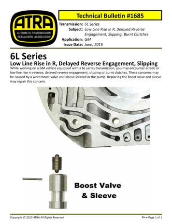
ME8651 Design of Transmission Systems Notes, Depart. of Mech. Engg. VTHT, AVADI, Chennai-62LetS1 Percentage slip between the driver and the belt,S2 Percentage slip between the belt and the driven pulley, andS Total percentage slip S1 S2Velocity ratio, [1 -] [1 -]If thickness of the belt (t) is considered, thenVelocity ratio, [1 -]Effect of Creep of BeltLetσ1 and σ2 Stresses in the belt on the tight side and slack side respectively, andE Young's modulus of the belt material.Velocity ratio, xGEOMETRICAL RELATIONSHIPSFor open belt drive:An open belt drive is shown in Fig.LetD and d Diameters of the larger and smaller pulleys respectively in meters,C Centre distance between the two pulleys in meters,L Total length of the belt in meters,2α The angle subtended between the straight portions of the belt in degrees,αs Wrap angle (or angle of contact/lap) for small pulley in degrees, andαL Wrap angle for large pulley in degrees.OPEN BELT DRIVEsin α alsoαs (180 - 2α) and αL (180 2α)5
ME8651 Design of Transmission Systems Notes, Depart. of Mech. Engg. VTHT, AVADI, Chennai-62andWrap angle for smaller pulley, α s 180 - 2 Sin-1 ()Wrap angle for larger pulley, αL 180 2 Sin-1 ()Length of the belt, L 2C ( ) (D d) For Crossed Belt Drive:sin α ()alsoαs αL (180 2α)Therefore, wrap angels for smaller and larger pulleys are same and is given byαs αL 180 2 Sin-1 (and)Length of the belt, L 2C ( ) (D d) STRESSES IN THE BELTThe various stresses acting at various portions of the belt are.1. Stress due to maximum working tension, TI (σ t):σt Where b width of the belt, andt Thickness of the belt.2. Stress due to bending of the belt over the pulley(σ b):(σb) Where E young‟s modulus of the belt over the pulley (σ b)d diameter of the smaller pulley3. Stress due to the effect of centrifugal force (σ c)(σc) 6 2
ME8651 Design of Transmission Systems Notes, Depart. of Mech. Engg. VTHT, AVADI, Chennai-62Where density of the belt material in Kg/m3It is noted that the stress will be maximum when the belt moves over the smaller pulley.Therefore the maximum stress in the tight side of the smaller pulley is given byσmax σ t σ b σ cPermissible stressesLeather belt 2 to 3.45 M PaRubber belt 1 to 1.7 M PaFabric belt Less that 1.5 M PaDESIGN OF FLAT BELT PULLEYSMaterials Used for PulleysThe commonly used pulley materials are: Fabricated steel Wood or fiber. Compressed paper Cast Iron pulleys are most widely used in actual practice.Cast ironDesign Procedure for Cast Iron PulleysThe cross-section of a cast iron pulley is shown in Fig.1.13. (Refer PSG data book, pageno. 7.56).D Diameter of the pulley,a Width of the pulley,b Thickness of the arm,d1 Diameter of the hub,d2 Diameter of the shaft, andI Length of the hub,t Thickness of the rim,1. Dimension of pulley:7
ME8651 Design of Transmission Systems Notes, Depart. of Mech. Engg. VTHT, AVADI, Chennai-62(i) Diameter of the pulley (D): Obtain the diameter of the pulley either from velocityration consideration or centrifugal stress consideration. We know that the centrifugal stressinduced in the rim of the pulley, c 2Where Density of the rim material. 7200 kg/m3 for cast iron, and Velocity of the rim D being the diameter of pulley and N the speedof the pulley.(ii)Width of the pulley (a): If the width of the belt is known, then select the width of thepulley referring to tables [from data book, page no. 7.54]2. Dimension of arms :(i) Number of arms (n): .[from data book, page no. 7.56]Number of arms(ii)Cross-section of arms (b and b/2):Major axis of elliptical section near the boss, b 2.94 2.94for single belt, andfor double belt.Minor axis of elliptical section near the boss (iii) Arms raper : The arms are tapered from hub to rim.Taper 4mm per 100mm(iv) Radius of the cross-section of arms : r b3. Dimensions of hub:(i) Diameter of hub(d1):Diameter of the hub(d1) (1.7 to 2.0)* Diameter of the shaft (d2)(ii)Length of the hub(l):Minimum length of bore, l aWhere, a width of pulley.4. Crowning of pulley rim:Selection of crown height (h): Knowing diameter (D) and width (a) of the pulley, selectthe crown height (h) referring to tables 1.7(a) and (b)Table 1.7(a). Crown of flat pulleys (40 to 355 mm diameter) (from data book, page no.7.55)(Crown is unrelated to the width in this diameter range)Table 1.7(b). Crown of flat pulleys (40 to 2000mm diameter) (from data book,page no.7.55)(Crown varies with the width in this diameter range)8
ME8651 Design of Transmission Systems Notes, Depart. of Mech. Engg. VTHT, AVADI, Chennai-62DESIGN OF FLAT BELTDRIVEThe two different design procedures used are:(i) Using the manufacturer's data, and(ii) Using the basic equations.DESIGN OF FLAT BELT DRIVE BASED ON MANUFACTURER'S DATA1. Selection of pulley diameters:Select the pulley diameters and angle of contact (i.e., wrap angle). By using the given beltspeed and assuming number of plies, minimum pulley diameter is chosen. Use Table tochoose the diameter of the smaller pulley.(from data book, page no. 7.52)2. Calculation of design power in KW:Calculate the design KW by using the relationship given belowDesign KW i. Load correction factor (ks): This factor is used to account for the nature of applicationand type of load. The value of Ks can be selected from table 1.9. (From data book, pageno. 7.53)ii. Arc of contact factor(kα):Arc of contact 180 –*60 .[from data book pg.no 7.54]Where D and d are Diameter of larger and smaller pulley resp.C is the centre distance.iii. Small pulley factor (kd):Table. Small pulley factor, K d (from data book, page no. 7.62)3. Selection of belting:Select a belt referring from table below.Table. Load rating of fabric belts per mm width per ply at 180 arc of contact at 10m/s beltspeed (from data book, page no.7.54)4. Load rating correction:Correct the load rating to the actual speed of the belt by using the relation given below.Load rating at V m/s Load rating at 10 m/s x [From data book, page no.7.54]5. Determination of belt width(b):Determine the belt width by using the following relation:Width of belt Knowing the smaller pulley diameter and velocity of the belt, and consulting table. Thenumber of plies can be found.The calculated belt width should be rounded off to the standard belt width by consultingTable. Standard widths of transmission belting (from data book no. 7.52)6. Determination of pulley width(B):9
ME8651 Design of Transmission Systems Notes, Depart. of Mech. Engg. VTHT, AVADI, Chennai-62Detemine the pulley width, by referring the tables1.6 (a and b)[From data book, page no.7.54]Table 1.6(a). Pulley width [From data book, page no. 7.54]Table1.6(b). Recommended series of width of flat pulley,mm[From data book, page no.7.55]7. Calculation of belt length (L):Calculation the length of the belt by using the equation given below.For open belt drive:L 2C ( (D d) [From data book, page no. 7.53]For crossed belt drive:L 2C ( (D d) [From data book, page no. 7.53]Where T1, T2, m, v and have usual meaning, and2 is the V- groove angle ( 1800 for flat belt)V -Belts and PulleysMaterials of V-beltsV -belts are made of cotton fabric and cords molded in rubber and covered with fabricandrubber, as shown in FigSpecification of V-beltsV-belts are designated by its type and nominal inside length. For example, a C2845belthas a cross-section of type C and has a nominal inside length of2845 mm.RATIO OF DRIVING TENSIONS FOR V-BELT Where TI and T2 Tensions in the tight and slack sides respectively,2β Angle of the groove, andµ Coefficient of friction between the belt and sides of the groove.Note. Number of V-belt 10
ME8651 Design of Transmission Systems Notes, Depart. of Mech. Engg. VTHT, AVADI, Chennai-62DESIGN OF SHEAVES (OR V-GROOVED PULLEYS)1. Materials of V-grooved pulleys:The commonly used sheave materials and their characteristics are summarized In Table 2.1.Table 2.1Material of sheavesCharacteristics and /or applications1. cast ironIt is economical, stable and durable also it hasexcellent friction characteristics on V-belts.2.Pressed steelIt is lighter and cheaper but it gives rise toexcessive belt slip wear and noise.3.Formed steelPrimarily used in automotive and agriculturalpurposes4.Diecast aluminumUsed for special applications2. Dimensions of sheaves:The cross-section of a sheave (i.e., V-grooved pulley) for V-belt drives IS shown In Fig.2.2.(Refer data book, page no. 7.70).whereIp Pitch width,I Face width,f Edge of pulley to first groove centre,e centre to centre distance of groovesdp pulley pitch diameter,b Minimum distance down to pitch line,h Minimum depth below the pitch line.Table 2.2 The various dimensions of standard V-grooved pulley in mm(from data book,page no. 7.70)Note Face width, l (n – 1) e 2fThe two different design procedures used are:(i) Using the manufacturer's data, and(ii) Using the basic equations.11
ME8651 Design of Transmission Systems Notes, Depart. of Mech. Engg. VTHT, AVADI, Chennai-62DESIGN OF V-BELT DRIVE BASED ON MANUFACTURER'S DATAThe design of V-belt is primarily concerned with the selection of belt section, selection ofpulley diameters, determination of number of belts and centre distance required for the giventransmitted power.DESIGN PROCEDURE:1. Selection of belt section:Consulting Table 2.3, select the cross-section of a belt (i.e., type of belt) depending onthepower to be transmitted. [From data book, page no. 7.58]2. Selection of pulley diameters (d and D):Select small pulley diameter (d) from Table 2.3. Then using the speed ratio, calculate thelarge pulley diameter (D). These pulley diameters should be rounded off to a standarddiameter by using Table 1.5. [From data book, page no. 7.58]3. Determination of nominal pitch length:Determine the length of the belt L (which is also known as nominal inside length) byusing the formula,L 2C [From data book, page no. 7.53]For the calculated nominal inside length and belt section, consulting Table 2.5, select thenext standard pitch length.Tile nominal pitch lengthis defined as the circumferential length of the belt at the pitchwidth (i. e., the width at the neutral axis of the belt). The value of the pitch width remainsconstant for each type of belt irrespective of the groove angle .For pitch length, add with inside length, 36 mm for A belt, 43 mm for B, 56 mm for C. 79mm for 0 and 92 mm for E belt.4. Selection of various modification factors:In order to calculate the design power thefollowing modification factors have to bedetermined.(i) Length correction factor (FC):Table.Nominal inside length, nominal pitch length and length correction/actor/or standardsizes 0/ JI-belts (from data book, page no. 7.58, 7.59 and 7.60) (The values for a fewcases only given)(ii) Correction factor for arc of contact (Fd): First determine the angle of contact (or arc of contact) of the smaller pulley. Arc of contact 180 -x60 [From data book, page no 7.68] For the calculated arc of contact, select the correction factor from Table 2.6. Arc of contact factor is taken into account because the power transmitted may belimited by slipping of the belt on the smaller pulley.Table 2.6.Arc 0/ contact/actor, Fd [From data book, page no. 7.68](The values/or a few cases are given below)(iii) Service factor (Fa): Select the service factor (Fa) consulting Table 2.7.12
ME8651 Design of Transmission Systems Notes, Depart. of Mech. Engg. VTHT, AVADI, Chennai-62 The service factor takes into account the severity of the load transmitted whichdepends upon the characteristics of the driving and driven units.Table 2.7.Service factor for V-Belts, Fa [From data book, page no. 7.69]Note. The details of driving units and driven machines under different duties are availablein thedata book, page no. 7.69.6. Calculation of maximum power capacity :Calculate the maximum power capacity (in kW) of a V-belt using the formulas given inTable 2.8. .[From data book, page no. 7.62]where kW Maximum power in kW at 1800 arc of contact for a belt of average length,S Belt speed, m/s,de Equivalent pitch diameter dpx Fb,dp Pitch diameter of the smaller pulley, mm, andF2 Small diameter factor to account for variation of arc of contact, fromTable 2.9. .[From data book, page no. 7.62]7. Determination of number of belts (nb):Determine number of belts the (nb) from the relation, .[From data book, page no. 7.70]WhereP Drive power, in kW,Fa Service factor for V-belts,KW Rated power (i.e., rating of a single V-belt),Fc Length correction factor, andFd Correction factor for arc of contact.8. Calculation of actual centre distance:Calculate the actual centre distance from the relation, [From data book, page no. 7.61]Cactual A Where A - [B ], andL Nominal pitch length of the belt from table 2.5 (refer step 4)WIRE ROPES AND PULLEYSMaterials of Wire RopesThe commonly used materials for wire ropes are \ wrought iron, cast steel, plow steel andalloy steel. For special purposes copper, bronze, aluminum alloys and stainless steel are alsoused.13
ME8651 Design of Transmission Systems Notes, Depart. of Mech. Engg. VTHT, AVADI, Chennai-62SPECIFICATION OF WIRE ROPESThe wire ropes are specified (or designated) by the number of strands and the number ofwires in each strand. For example, a 6 x 7 rope means a rope made from six strands withseven wires in each strand.GUIDELINES FOR THE SELECTION OF WIRE ROPEThe wire rope is selected based on its application. The shows the standard designation ofwire ropes and their applications.STRESSES IN WIRE ROPESThe various types of stresses induced in a wire rope are:1. Direct stress due to the weight of the load to be lifted and weight of the rope ( d):LetW Weight of the load to be lifted,W Weight of the rope, andA Area of useful cross-section of the rope.Direct stress 2. Bending stress when the rope passes over the sheave or drum ( b):Bending stress,Where modulus of elasticity of the wire rope 0.84*N/, for steel ropes of ordinary construction, *E, E Modulus of elasticity of the wire material diameter of the wire,D diameter of sheave.3. Stress due to acceleration ( a):Due to change in speed, an additional stress is induced. The stress due to acceleration is givenby (Where )a Acceleration of rope and local during hoisting (not at starting or stopping); (v2-v1) is the change in speed in „t‟ seconds.14
ME8651 Design of Transmission Systems Notes, Depart. of Mech. Engg. VTHT, AVADI, Chennai-624. Stress during starting and stopping ( st):(i) When there is no slack in the rope: st 2 x d(ii) When there is slack in the rope before starting or slopping, then there will be aconsiderable impact load on the rope. st [1 ]Where as Acceleration during starting or stopping,h Slack during starting, andl Length of the rope.Effective stress:(i) Effective stress in the rope during normal working, en d b(ii) Effective stress in the rope during starting, est st b(iii) Effective stress in the rope during acceleration of the load, ea d b aRECOMMENDED FACTOR OF SAFETY FOR WIRE ROPESThe recommended factor of safety for wire ropes based on .the ultimate strength are givenin Table.Table.Recommended factor of safety for wire ropes, n' (from data book, page no. 9.1)DESIGN OF WIRE ROPESDESIGN PROCEDURE FOR A WIRE ROPE1. Selection of suitable wire rope:First select the suitable type of wire rope for the given application, from Table 3.1.2. Calculation of design load:Calculate the design load by assuming a larger factor of safety, say 15 (or find the designload by assuming a factor of safety 2 to 2.5 times the factor of safety given in Table 3.2).Design load Load to be lifted x Assumed factor of safety3. Selection of wire rope diameter (d):Select the wire rope diameter (d) from Table 3.4, Group 6 x 19 (from data book, page no.9.5 and 9.6) by taking the design load as the breaking strength.4. Calculation of sheave diameter (D :Consulting Table 3.5. (from data book, page no. 9.1) obtain the diameter of sheave (ordrum). Always larger sheave diameter is preferred. Ratio for 50 m/min of rope speeds - to be increased by 8% for each 'additional speedof 50m/min5. Selection of the area of useful cross-section of the rope (A):Consulting Table 3.6, select the area of useful cross-section of the rope.15
ME8651 Design of Transmission Systems Notes, Depart. of Mech. Engg. VTHT, AVADI, Chennai-62Metallic area of rope A, mm20.38 d20.4d20.4d2Type of construction6x76 x 196 x 376. Calculation of wire diameter (dw):Calculate the diameter of wire using the relationdw wherei Number of wires in the rope Number of strands x Number of wires in each strand.7. Selection of weight of rope (W,):Obtain the rope weight (Wr) from Table 3.4.8. Calculation of various loads:Calculate the various loads using the relations given below.(i) Direct load, Wd W Wr(ii) Bending load, Wb b x A Er.xA(iii) Acceleration load due to change in the speed of hoisting,Wa [Wherea ]a(When speed of the rope changes from v1 to v2 in t seconds)(iv) Starting or stopping load:(a) When there is no slack in the rope:Starting load, WS1 2· Wd 2 (W Wr)(b) When there is slack in the rope:Starting load, Wst st x A (W Wr) [1 ]9. Calculation of effective loads:(i) Effective load on the rope during normal working, Wen Wd Wb(ii) Effective load on the rope during acceleration of the load, Wea Wd Wb Wa(iii) Effective load on the rope during starting, West Wb Wst10. Calculation of working (or actual) factor of safety (FS w):Working factor of safety, FS w 11. Check for safe design:Compare the calculated working factor of safety (FS w) with the recommended factor ofsafety (n') given in Table 3.2. If the working factor of safety is greater than therecommended factor of safety (i. e., FSw n'), then the design is safe and satisfactory.16
ME8651 Design of Transmission Systems Notes, Depart. of Mech. Engg. VTHT, AVADI, Chennai-62If FSw n', then the design is not satisfactory. Now choose some other rope with greaterbreaking strength or increase the number of ropes.12. Calculation of number of ropes:Number of ropes FAILURE OF ROPESThe amount of wear that occurs depends upon the pressure between the rope and thesheave and is givenP T Tension in roped Diameter of rope, andD sheave diameterCHAIN DRIVESTYPES OF CHAIN DRIVESThe common types of chains are:1. Link chains (or welded chains),2. Transmission chains (or roller chains,) and3. Silent chains (or inverted tooth chains).LINK CHAINSLink chains, also known as welded load chains, are widely used In low capacity hoisting machines such as hoists, winches and hand operatedcranes as the main lifting appliances. As slings for suspending the load from the hook or other device.DIMENSIONS OF A LINK CHAINThey are pitch (t) equal to the inside length of the link, outside width (B) and diameter (d)of the chain bar.CLASSIFICATION OF LINK CHAINS1. Depending on the ratio between the pitch and the diameter of the chain bar:(a) Short link chains: If t 3 d, then the chains are known as short link chains.(b) Long link chains: If I 3 d, then the chains are known as long link chains.2. Depending on the manufacturing accuracy:(a) Pitched chains: When the permissible deviations from the nominal pitch size is17
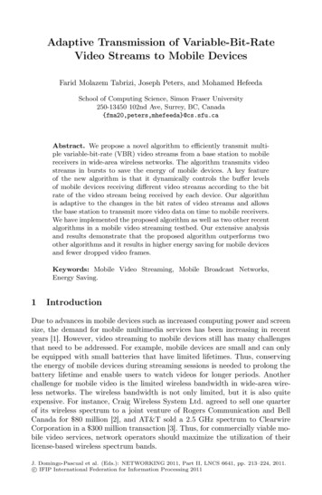
ME8651 Design of Transmission Systems Notes, Depart. of Mech. Engg. VTHT, AVADI, Chennai-62within 0.03 d and from the outside width is within 0.05 d, then the chain is called asPitched chain.(b) Calibrated chains :When the permissible deviations is within i 0.1 d of the nominalSize in pitch and outside width, then the chain is known as calibrated chain.SELECTION OF LINK CHAINSThe general formula for selecting link chains in tension is given by Safe load carried by the chain, Breaking load of the chain, andn Factor of safetyTRANSMISSION (OR ROLLER) CHAINSCHAIN MATERIALS Link plates are made of cold-rolled, medium-carbon or alloy steels such asC45,C50 and 40 Crl. Pins, bushings and rollers are made of carburizing steels such as CIS, C20, and30 Ni4 Crl.SPECIFICATION OF A ROLLER CHAINRoller chain is specified by three dimensions - pitch, width and diameter.Pitch:It is the distance from centre to centre of adjacent pins or rivets.Width:It is the nominal width of the link or the length of the pin.Diameter:It refers to the actual outside diameter of the roller.Roller chains are available in single-row or multi-row construction such as simplex, duplex ortriplex strands as shown in Fig. (Refer data book, page no. 7.71).18
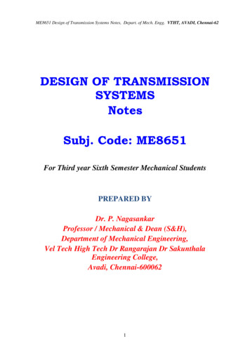
ME8651 Design of Transmission Systems Notes, Depart. of Mech. Engg. VTHT, AVADI, Chennai-62Shows a sprocket driving a chain in a counter clockwise direction.Letp Chain pitch,a Pitch angle, /2 Angle of articulation,D Pitch circle diameter of the sprocket, andz Number of teeth on the sprocket.CHORDAL (OR POLYGONAL) ACTIONSPROCKET DIAMETERS19
ME8651 Design of Transmission Systems Notes, Depart. of Mech. Engg. VTHT, AVADI, Chennai-62The equations for those diameters are :(i) Pitch diameter (ii) Outside diameter p[0.6 cot ()](iii) Bottom diameter Pitch diameter – Roller outside diameter(iv) Caliper diameter Pitch diameter x cos ((v) Maximum hub diameter p [cot () - 1] – 0.03TOOTH FORMDESIGN OF SILENT CHAINSILENT (OR INVERTED-TOOTH) CHAIN20
ME8651 Design of Transmission Systems Notes, Depart. of Mech. Engg. VTHT, AVADI, Chennai-62TYPES OF SILENT CHAINSDepending upon the type of joint between links, the silent chains are classified into:(i) Reynolds chain: In Reynolds chain, the links are connected by pins resulting in slidingfriction.(ii) Morse chain: In Morse chain, the rocker pins are used.DESIGN PROCEDURE OF ROLLER CHAIN1. Selection of the transmission ratio (i):Select a preferred transmission ratio, i (from data book, page no. 7.74)1, 1.12, 1.25, 1.4, 1.6, 1.8, 2, 2.25, 3.15, 4, 4.5, 5, 5.6, 6.3 and 7.1From the pitch range obtained, consulting Table 4.4, select a suitable standardpitch.(From data book, page no. 7. 74)2. Selection of number of teeth on the driver sprocket (Z1):Select the number of teeth on the driver sprocket (Z1) .[From data book, page no. 7.74]3. Determination of number of teeth on the driven sprocket (Z2):Z2 i* Z1 .[From data book, page no. 7.74]Recommended value of Z2:Z2max 100 to 120 .[From data book, page no. 7.74]4. Selection of standard pitch (p):a (30 to 50)pa 30pmaxa 50pminFrom the pitch range obtained, consulting table 4.4, select a suitable standard pitch.[From data book, page no. 7.74]5. Selection of the chain:(From data book, page nos. 7.71, 7.72 and 7. 73.This table gives some details for a few Chains.)Note R - Simplex, DR - Duplex, TR – Triplex6. Calculation of Total load on The Driving Side of the Chain (PT): PT Pt Pc Ps .[From data book, page no. 7.78]21
ME8651 Design of Transmission Systems Notes, Depart. of Mech. Engg. VTHT, AVADI, Chennai-62(i) To find tangential force (Pt):Pt Where [From data book, page no. 7.78]N Transmitted power in KW, and Chain velocity in m/s or(ii) To find centrifugal tension (Pc):Pc m 2 [From data book, page no. 7.78]Wherem Mass of chain / meter,V velocity of chain , m/s(iii) To find tension due to sagging (Ps):Ps k . w. awheredrive,k Coefficient of sag taking into account the arrangement of chainW Weight of chain / meter m- g, anda Centre distance in meter.Coefficient for sag, k [From data book, page no. 7.76]7. Calculation of service factor (K s):The service factor is used to account for variations in the driving and driven sourcesfor roller chains.Service factor, Ks k1. k2.k3. k4. k5. k6 [From data book, page no. 7.76]k1 Load factor , (from data book, page no.7.76)k2 Factor for distance regulation, (from data book, page no.7.76)k3 Factor for centre distance of sprockets, (from data book, page no.7.76)k4 Factor for position of sprocket(from data book, page no.7.77)k5 Lubrication factor (from data book, page no.7.77)k6 Rating factor(from data book, page no.7.77)8. Calculation of design load:Design load Total load on the driving side of the chain x Service factorDesign load PT x Ks9. Calculation of working factor of safety (FS w):Factor of safety Where Q is breaking load got from data book, page no.7.7222
ME8651 Design of Transmission Systems Notes, Depart. of Mech. Engg. VTHT, AVADI, Chennai-6210. Check for factor of safety:[Refer From data book, page no. 7.77]If the working factor of safety (FS w) is greater than the recommended minimum valueof factor of safety (n‟) then the des
DESIGN OF FLAT BELT DRIVE BASED ON MANUFACTURER'S DATA 1. Selection of pulley diameters: Select the pulley diameters and angle of contact (i.e., wrap angle). By using the given belt speed and assuming number of plies, minimum pulley diameter is chosen. Use Table to choose the diameter of the smaller pulley.(from data book, page no. 7.52) 2.