Transcription
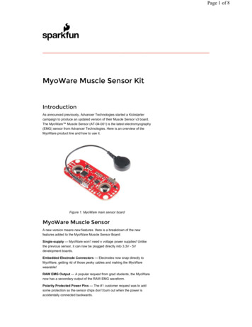
Pulse Sensor Getting Started GuideIntroduction:Pulse Sensor is a well-designed plug-and-play heart-rate sensor for Arduino. It can be used bystudents, artists, athletes, makers, and game & mobile developers who want to easily incorporate live heartrate data into their projects. The sensor clips onto a fingertip or earlobe and plugs right into Arduino with somejumper cables. It also includes an open-source monitoring app that graphs your pulse in real time.The Pulse Sensor Kit includes:
1) A 24-inch Color-Coded Cable, with (male) header connectors. You'll find this makes it easy to embed thesensor into your project, and connect to an Arduino. No soldering is required.2) An Ear Clip, perfectly sized to the sensor. We searched many places to find just the right clip. It can be hotglued to the back of the sensor and easily worn on the earlobe.3) 2 Velcro Dots. These are 'hook' side and are also perfectly sized to the sensor. You'll find these velcro dotsvery useful if you want to make a velcro (or fabric) strap to wrap around a finger tip.4) Velcro strap to wrap the Pulse Sensor around your finger.4) 3 Transparent Stickers. These are used on the front of the Pulse Sensor to protect it from oily fingers andsweaty earlobes.5) The Pulse Sensor has 3 holes around the outside edge which make it easy to sew it into almost anything.Let’s get started with Pulse Sensor AnatomyThe front of the sensor is the pretty side with the Heart logo. This is the side that makes contact withthe skin. On the front you see a small round hole, which is where the LED shines through from the back, andthere is also a little square just under the LED. The square is an ambient light sensor, exactly like the one usedin cellphones, tablets, and laptops, to adjust the screen brightness in different light conditions. The LED shineslight into the fingertip or earlobe, or other capillary tissue, and sensor reads the light that bounces back. Theback of the sensor is where the rest of the parts are mounted. We put them there so they would not get in theway of the of the sensor on the front. Even the LED we are using is a reverse mount LED. For more about thecircuit functionality, check out the Hardware page.[needs link]The cable is a 24” flat color coded ribbon cable with 3 male header connectors.
RED wire 3V to 5VBLACK wire GNDPURPLE wire SignalThe Pulse Sensor can be connected to arduino, or plugged into a breadboard. Before we get it up andrunning, we need to protect the exposed circuitry so you can get a reliable heart beat signal.Preparing the Pulse SensorBefore you really start using the sensor you want to insulate the board from your (naturally) sweaty/oilyfingers. The Pulse Sensor is an exposed circuit board, and if you touch the solder points, you could short theboard, or introduce unwanted signal noise. We will use a thin film of vinyl to seal the sensor side. Find thesmall page of four clear round stickers in your kit, and peel one off. Then center it on the Pulse Sensor. Itshould fit perfectly.When you are happy with the way it’s lined up, squeeze it onto the face all at once! The sticker (madeof vinyl) will kind of stretch over the sensor and give it a nice close fit. If you get a wrinkle, don’t worry, justpress it down really hard and it should stick. We gave you 4, so you can replace it if necessary.That takes care of the front side. The vinyl sticker offers very good protection for the underlying circuit,and we rate it ‘water resistant’. meaning: it can stand to get splashed on, but don’t throw it in the pool!If this is your first time working with Pulse Sensor, you’re probably eager to get started, and not sure ifyou want to use the ear-clip or finger-strap (or other thing). The back of the Pulse Sensor has even moreexposed contacts than the front, so you need to make sure that you don’t let it touch anything conductive orwet.
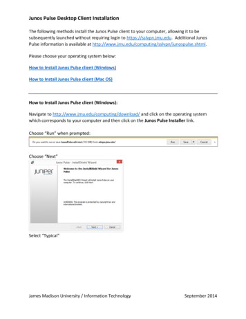
The easiest and quickest way to protect the back side from undesireable shorts or noise is to simplystick a velcro dot there for now. The dot will keep your parts away from the Pulse Sensor parts enough for youto get a good feel for the sensor and decide how you want to mount it. You’ll find that the velcro dot comes offeasily, and stores back on the little strip of plastic next to the other one.Notice that the electrical connectionsare still exposed! We only recommendthis as a temporary setup so you canget started. We show you how to betterseal the Pulse Sensor later in thisdocument.Running The Pulse Sensor CodeGet the latest Arduino and Processing Pulse Sensor software here http://pulsesensor.com/downloads/Arduino code is called “PulseSensorAmped Arduino-xx”The Processing code is called “PulseSensorAmped Processing-xx”We strongly advise that you DO NOT connect the Pulse Sensor to your body while your computer or arduino isbeing powered from the mains AC line. That goes for charging laptops and DC power supplies. Please be safeand isolate yourself from from the power grid, or work under battery power.Connect the Pulse Sensor to: V (red), Ground (black), and Analog Pin 0 (purple) on your favorite Arduino, orArduino compatible device, and upload the ‘PulseSensoAmped Arduino-xx’ sketch.note: If you want to power Pulse Sensor Ampedwith low voltage (3.3V for example), make sureyou have this line of code in the setup()analogReference(EXTERNAL);Also, make sure that you apply the lower voltageto the Arduino Aref pin (next to pin 13).After it’s done uploading, you should see Arduino pin 13 blink in time with your heartbeat when you hold thesensor on your fingertip. If you grip the sensor too hard, you will squeeze all the blood out of your fingertip andthere will be no signal! If you hold it too lightly, you will invite noise from movement and ambient light. Sweet
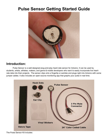
Spot pressure on the Pulse Sensor will give a nice clean signal. You may need to play around and try differentparts of your body and pressures. If you see an intermittent blink, or no blink, you might be a zombie or a robot.To view the heartbeat waveform and check your heart rate, you can use the Processing sketch that wemade. Start up Processing on your computer and run the ‘PulseSensorAmped Processing-xx’ sketch. This isour data visualization software, and it looks like this.note: If you get an error when starting this code, you may need to make sure you are selecting the rightserial port. Check the Troubleshooting section below.The large main window shows a graph of raw sensor data over time. The Pulse Sensor Data Window can bescaled using the scrollbar at the bottom if you have a very large or very small signal. At the right of the screen,a smaller data window graphs heart rate over time. This graph advances every pulse, and the Beats PerMinute is updated every pulse as a running average of the last ten pulses. The big red heart in the upper rightalso pulses to the time of your heartbeat. When you hold the Pulse Sensor to your fingertip or earlobe or (fill inbody part here) you should see a nice heartbeat waveform like the one above. If you don’t, and you’re sureyou’re not a zombie, try the sensor on different parts of your body that have capillary tissue. We’ve had goodresults on the side of the nose, middle of the forehead, palm, and lower lip. We’re all different, originalorganisms. Play around and find the best spot on you and your friends. As you are testing and getting used tothe sensor. You may find that some fingers or parts of fingers are better than others. For example, I find thatwhen I position the sensor so that the edge of the PCB is at the bottom edge of my earlobe I get an awesomesignal. Also, people with cold hands or poor circulation may have a harder time reading the pulse. Run yourhands under warm water, or do some jumping-jacks!Arduino and Processing programming environments available for download here:www .arduino.cc www .processing.org
Sealing the Back Side of Pulse SensorBasic protection for the back of the Pulse Sensorand prep for attaching Velcro Dot.It’s really important to protect the exposed Pulse Sensor circuitry so the sweat of your fingertips or earlobe (orwherever) doesn’t cause signal noise or a short circuit. This How-To uses hot glue, which can be removedeasily or re-worked if you want to change where you’ve stuck your Pulse Sensor. We love hot glue!The other things you’ll need are:Hot Glue GunBlue Tape (any tape should do ok)Nail Trimmers (or your favorite trimming device. Flush-cut wire snips work well too)Read these instructions all the way through before you start!First, attach the clear vinyl sticker to the front of your Pulse Sensor, as shown above. Then put a blob ofhot glue on the back, right over the circuit. Size can be difficult to judge sometimes. What I meant was put ahot glue blob about the size of a kidney bean on the back side of the Pulse Sensor.Then, while the glue is still very hot, press the Pulse Sensor glue-side-down onto the sticky side of a piece ofblue tape (I believe that blue tape has magical properties, but if you don’t have blue tape other kinds of tapewill work just as well).note: The tallest thing on the back of the Pulse Sensor isthe green LED housing right in the middle. Use it to makethe hot-glue seal thin and strong. When you press evenlyuntil the back of the LED touches, all the conductive partswill be covered with hot glue. If the glue doesn’t ooze outall around, let it cool down, then peel if from the PulseSensor and try again. Once the glue has cooled down andhas some body, you can peel it off easily. Here’s somepics of hot glue ‘impressions’ that I took during the makingof this guide.
Next put a small dab of hot glue on the frontof the cables, where they attach to the PulseSensor circuit board. This will bond to the otherglue that’s there and act as a strain-relief for thecable connection. This is important because thecable connection can wear out over time.Once the hot glue has cooled (wait for it!)the blue tape will peel off very easily. Checkyour work to make sure that there are notexposed electrical connections!Next is trimming. I find the easiest way is touse nail clippers. Flush cutting wire snips worktoo. Take care not to clip the wires!!!And leave enough around the cable to actas a good strain-relief
This is the basic Pulse Sensor Hot Glue Seal, It’s also got the clear vinyl sticker on the front face. We’re callingthis ‘Water Resistant’, ready to be handled and passed around from fingers to earlobes or whatever. It is notadvised to submerge or soak the Pulse Sensor with this basic seal.Now you can stick on the velcro dot (included) and make a finger strap with the velcro tape (included)!
Attaching the Ear ClipWe looked all over, and were lucky enough to find an ear clip that fits the Pulse Sensor perfectly. Theearlobe is a great place to attach Pulse Sensor. Here’s some instruction on how to do it.It is important to apply some strain relief to the cable connection where it meets the Pulse Sensor PCB.The little wire connections can wear out and break (or short on something) over time. We can do this with hotglue, like we did in the previous example.First, attach a clear vinyl sticker to the front of the Pulse Sensor if you have not already. Then, put asmall dab of hot glue on the front of the cables right where they meet the PCB. Get some on the edge of thePCB too, that will help. Remember, if you don’t like the blob you’ve made for any reason, it’s easy to removeonce it cools down.Next place the Pulse Sensor face down, and put a dab of glue about the size of a kidney bean on theback as illustrated above. Center the round part of the ear clip on the sensor and press it into the hot glue. Thetallest component on the back is the plastic body of the reverse mount LED, and if you press it evenly it willhelp keep the metal of the ear clip from contacting any of the component connections.Allow the hot glue to ooze out around the ear clip. That will ensure good coverage. Take care not to letthe hot glue cover around the ear clip hinge, as that could get in the way of it working. Trimming is easy withnail clippers (as above) or your trimming tool of choice. Don’t trim the wires by mistake!!!Take a good look at your work with a magnifying glass to be sure that you haven't made contact with any ofthe solder joints, then plug it in and test it. Hot glue is also great because it is easy to remove or re-work if youneed to.Troubleshooting:
Processing Sketch gives me a COM port error at startup.Make sure you are plugged into an Arduino board, that it is working correctly, and running our firmware.Check to see if you have the right serial port. The code underlined in red should match the correct portnumber in the terminal window at the bottom of Processing IDE.Processing gives an RXTX mismatch warning, then nothing happensThe RXTX mismatch problem can be resolved by making sure you are running the latest version ofProcessing and Arduino.If you’re still having trouble, go to ndex.html for more info.
sensor into your project, and connect to an Arduino. No soldering is required. 2) An Ear Clip, perfectly sized to the sensor. We searched many places to find just the right clip. It can be hot-glued to the back of the sensor and easily worn on the earlobe. 3) 2 Velcro Dots. These ar