Transcription
Application TechniqueApplication Guidelines for 12-Pulse Operation of PowerFlex750-Series AC Drives
Application Guidelines for 12-Pulse Operation of PowerFlex 750-Series AC DrivesImportant User InformationRead this document and the documents listed in the additional resources section about installation, configuration, andoperation of this equipment before you install, configure, operate, or maintain this product. Users are required tofamiliarize themselves with installation and wiring instructions in addition to requirements of all applicable codes, laws,and standards.Activities including installation, adjustments, putting into service, use, assembly, disassembly, and maintenance are requiredto be carried out by suitably trained personnel in accordance with applicable code of practice.If this equipment is used in a manner not specified by the manufacturer, the protection provided by the equipment may beimpaired.In no event will Rockwell Automation, Inc. be responsible or liable for indirect or consequential damages resulting from theuse or application of this equipment.The examples and diagrams in this manual are included solely for illustrative purposes. Because of the many variables andrequirements associated with any particular installation, Rockwell Automation, Inc. cannot assume responsibility orliability for actual use based on the examples and diagrams.No patent liability is assumed by Rockwell Automation, Inc. with respect to use of information, circuits, equipment, orsoftware described in this manual.Reproduction of the contents of this manual, in whole or in part, without written permission of Rockwell Automation,Inc., is prohibited.Throughout this manual, when necessary, we use notes to make you aware of safety considerations.WARNING: Identifies information about practices or circumstances that can cause an explosion in a hazardous environment,which may lead to personal injury or death, property damage, or economic loss.ATTENTION: Identifies information about practices or circumstances that can lead to personal injury or death, propertydamage, or economic loss. Attentions help you identify a hazard, avoid a hazard, and recognize the consequence.IMPORTANTIdentifies information that is critical for successful application and understanding of the product.Labels may also be on or inside the equipment to provide specific precautions.SHOCK HAZARD: Labels may be on or inside the equipment, for example, a drive or motor, to alert people that dangerousvoltage may be present.BURN HAZARD: Labels may be on or inside the equipment, for example, a drive or motor, to alert people that surfaces mayreach dangerous temperatures.ARC FLASH HAZARD: Labels may be on or inside the equipment, for example, a motor control center, to alert people topotential Arc Flash. Arc Flash will cause severe injury or death. Wear proper Personal Protective Equipment (PPE). Follow ALLRegulatory requirements for safe work practices and for Personal Protective Equipment (PPE).Allen-Bradley, PowerFlex, Rockwell Software, and Rockwell Automation are trademarks of Rockwell Automation, Inc.Trademarks not belonging to Rockwell Automation are property of their respective companies.2Rockwell Automation Publication 750-AT003A-EN-P - March 2014
Application Guidelines for 12-Pulse Operation of PowerFlex 750-Series AC DrivesDocument ScopeThe scope of this document is to provide application guidelines for 12-pulseoperation of PowerFlex 750-Series, frames 6 10, 400V 690V AC input drives.While several different transformer configurations are possible, only thecommonly used delta-delta-wye transformer, which provides 30 degree phaseshift between the two sets of secondary windings is addressed. The guidelinesinclude sizing of the transformer and rectifier, grounding considerations, precharge, and circuit protection recommendations.Drive Harmonics and Impacton Supply NetworkStandard AC drive topologies consist of AC-DC-AC power conversion with a3-phase, 6-pulse rectifier bridge consisting of diodes or SCRs. An AC drive is anon-linear load on the utility power supply; a buffered (with AC line reactor orDC link choke) 6-pulse bridge generates close to 40% current total harmonicdistortion (THD). In addition, harmonic currents produced by a rectifier are thecause of voltage THD at the secondary of the transformer that feeds other loadsas well – generally referred to as a point of common coupling (PCC). The extentof voltage distortion depends on the stiffness of the power supply (kVA ratingand impedance of the transformer or generator). The stiffness of the powersupply is measured by the short circuit ratio, which is the ratio of the availableshort-circuit current to the rated full load current.The one-line diagram in Figure 1 illustrates a typical industrial plant with ACdrive loads, and different PCC where harmonic distortion measurements couldbe made. The dominant harmonics for 6-pulse, 12-pulse and 18-pulse rectifiersare {5th, 7th}, {11th, 13th} and {17th, 19th} respectively.Figure 1 - Typical Power Distribution with Harmonic Distortion Measurement ablePCC1PCC2PCC3LinearLoadOtherCustomerRockwell Automation Publication 750-AT003A-EN-P - March 2014ACDriveLinearLoadACDrive3
Application Guidelines for 12-Pulse Operation of PowerFlex 750-Series AC DrivesFigure 2 is the equivalent circuit for power distribution of Figure 1. Non-linearloads are represented by current sources at multiple characteristic harmonicfrequencies.Figure 2 - Non-linear Load Current SourcesUtility orGeneratorPCC2PCC1LinearLoadPCC3LinearLoad Non -linear Drive LoadOtherCustomerThe harmonic current magnitudes in Figure 2 depend on the source stiffness andany internal or external buffering (DC link choke or AC line reactor) in the ACdrive. When the harmonics currents generated by non-linear loads flow throughthe system impedances, voltage distortion is created. This affects other loadsconnected at the PCC nodes. With a generator source that has high internalimpedance (typically 25%), significant voltage distortion could be created bynon-linear loads, which could adversely affect other loads at the PCC nodes.Background voltage distortion, such as pre-existing voltage harmonics or voltageunbalance, can also affect the current harmonic distortion of non-linear loads.This is particularly true for multi-pulse rectifiers that rely on special transformerconfigurations to generate phase-shifted voltages, as will be discussed later in thisdocument for 12-pulse drive systems.Harmonics standards, such as IEEE 519-1992, specify maximum current THDand limits for individual harmonic current magnitudes (Table 10.3 of IEEE519-1992), and voltage THD (Table 10.2 of IEEE 519-1992) at the PCC, as afunction of the short-circuit ratio. While PCC in this definition refers to PCC1shown in Figure 1, customers may expect conformance to the specifications atPCC2 or PCC3 shown in Figure 1, where linear and non-linear loads areconnected.The detrimental effects of harmonics include increased losses in powerdistribution and generators, de-rating of transformers due to harmonic currents,and susceptibility of loads to voltage distortion. To determine transformer derating, a quantity called the K-factor, defined as follows, is used (I1 is thefundamental current and In is the harmonic current of order n). The K-factor for6-pulse and 12-pulse drives is about 6 and 2 respectively, while it is nearly equal tothe ideal value of 1 for 18-pulse drives. Background voltage distortion andunbalance will affect this significantly, particularly for 12-pulse and 18-pulsedrives that require special phase-shifting transformer configurations.4Rockwell Automation Publication 750-AT003A-EN-P - March 2014
Application Guidelines for 12-Pulse Operation of PowerFlex 750-Series AC DrivesTransformer de-rating as a function of K-factor is shown in Figure 3.Figure 3 - Transformer De-rating for Non-linear Loads2Σ 2 ( I / I1 ) Σ 2(I / I1 )2Rockwell AutomationWeb-Based HarmonicsSimulation ToolsWeb-based harmonics simulation tools provided by Rockwell Automation arepart of a suite of simulation tools hosted by Transim Technology Corporation.Users are only required to have an internet connection and a web browser to runthe simulation on a remote server. All Rockwell Automation employees anddistributors have access to the tool and must connect from within the RockwellAutomation firewall.The web-based simulation tools can be accessed at:http://webdc.transim.com/rockwellCurrently, there are two harmonics simulation tools, which are intended fordifferent applications as described below.Spreadsheet-Based Harmonics Calculator ToolThe harmonics calculator is a spreadsheet based tool, which uses look-uptables to estimate the voltage and current harmonics at different nodes in anetwork consisting of multiple linear and non-linear loads. Onlynumerical outputs are provided including checks for conformance toharmonics standards. This tool is more flexible than the harmonicssimulator tool in terms of the load configurations that can be simulated.Rockwell Automation Publication 750-AT003A-EN-P - March 20145
Application Guidelines for 12-Pulse Operation of PowerFlex 750-Series AC DrivesThe harmonics calculator doesn’t take into account the effects of preexisting voltage distortion or unbalance. Interaction between loads is alsonot considered. The harmonic contributions of different loads arenumerically added, without considering phase shift. Hence, the results areconservative.The system configuration can be specified on the landing page for theharmonics calculator tool, as shown in Figure 4. The Notes tab has usefulinformation on how to use the program, criteria for pass/fail andassumptions made to calculate harmonics. The Tutorial tab has anillustrative example with instructions on how to use system one-linediagrams to enter data into the harmonics calculator.Figure 4 - Web-based Harmonics Calculator Tool Data Input PageThe General Parameters section, bottom left in Figure 4, are default values andshould work in most applications. The Notices section is active after a simulationrun and includes design checks (for example, transformer rating exceeded) anduseful information like Active Filter current rating required to meet targetcurrent THD.6Rockwell Automation Publication 750-AT003A-EN-P - March 2014
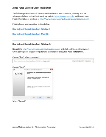
Application Guidelines for 12-Pulse Operation of PowerFlex 750-Series AC DrivesDifferent topologies of 6-pulse, 12-pulse and 18-pulse drives can be specified, asshown in Figure 5. For the delta-delta-wye 12-pulse transformer, the ISO xfmroption can be used. This tool doesn’t consider the effect of transformerimpedance mismatch and circulating currents, which will be explained later inthis document.Figure 5 - Web-based Harmonics Calculator Tool, 6-pulse, 12-pulse and 18-pulse DriveConfigurationsApplication ExampleThis application example demonstrates the effect of multi-pulse rectifiers onvoltage and current distortion.For a system consisting of a 2 MVA utility transformer, 1.5 MVA usertransformer and 700 Hp, 6-pulse load (buffered with DC link choke), the voltageand current THD at the 3 PCC points as identified in Figure 4, conformance tothe IEEE 519 standard, and the active filter current rating required to meet targetcurrent THD of 5% at PCC1 and PCC2 are shown in Figure 6 on page 8.Rockwell Automation Publication 750-AT003A-EN-P - March 20147
Application Guidelines for 12-Pulse Operation of PowerFlex 750-Series AC DrivesThe Results (top) section in Figure 6 shows voltage and current THD at 3 PCCnodes. The Intermediate calculations (bottom) section shows intermediatecalculations for harmonic currents, voltages and active filter current ratingrequired to meet 5% current THD.Figure 6 - Harmonics Calculator Simulation Results for 6-pulse Drive Load8Rockwell Automation Publication 750-AT003A-EN-P - March 2014
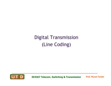
Application Guidelines for 12-Pulse Operation of PowerFlex 750-Series AC DrivesThe results of a 700 Hp drive with a 12-pulse rectifier (delta-delta-wye isolationtransformer) are shown in Figure 7. Note that the 12-pulse rectifier considerablyreduces current and voltage distortion, and helps meet the IEEE 519 limits forcurrent THD at PCC1 and PCC2 (limit is 8% based on the short-circuit ratio).The Results (top) section in Figure 7 shows the voltage and current THD at 3PCC nodes. The Intermediate Calculations section show the intermediatecalculations for harmonic currents, voltages and active filter current ratingrequired to meet 5% current THD.Figure 7 - Harmonics Calculator Simulation Results for 12-pulse Drive LoadRockwell Automation Publication 750-AT003A-EN-P - March 20149
Application Guidelines for 12-Pulse Operation of PowerFlex 750-Series AC DrivesHarmonics Circuit Simulator ToolThe harmonics simulator is a circuit simulation tool with one or two loadbranches. Each of the loads can be set to be of a specific type. Waveformsof voltage and current at different points of common coupling aregenerated along with numerical values for voltage and current THD, andchecks for conformance to harmonics standards.The one-line diagram of the system that is simulated is shown in Figure 8.On each branch, the load can only be of a certain type; currently only6-pulse or 18-pulse drives are supported on each individual transformer.Pre-existing distortion at the output of the utility transformer, 5thharmonic and voltage unbalance, can be set. Transformer B can be set toeither delta-delta or delta-wye. To simulate a 12-pulse load, 6-pulse loadsmust be added on each transformer, and Transformer B must be set todelta-delta.Figure 8 - Web-based Harmonics Circuit Simulation Tool Data Input Page10Rockwell Automation Publication 750-AT003A-EN-P - March 2014
Application Guidelines for 12-Pulse Operation of PowerFlex 750-Series AC DrivesWaveforms of voltage and current at the output of Transformer A, voltage andcurrent THD are shown in Figure 9.Figure 9 - Harmonics Simulator Results for 6-pulse, Single-branch LoadRockwell Automation Publication 750-AT003A-EN-P - March 201411
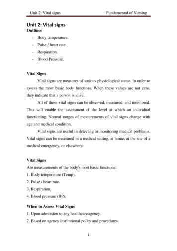
Application Guidelines for 12-Pulse Operation of PowerFlex 750-Series AC Drives12-pulse DriveConfigurationsThere are two main configurations of 12-pulse systems; true 12-pulse, and quasi12-pulse systems, as shown in Figure 10. In the true 12-pulse system, 3-phasevoltages from the utility transformer are converted to two sets of 3-phase voltageswith 30 degrees of phase shift between the sets. Each set of 3-phase voltages arefed to a full wave bridge rectifier, whose DC output has 12 pulses perfundamental line cycle. A common method to achieve the 30 degrees of phaseshift is to use a transformer with delta and wye secondary windings.In the quasi 12-pulse system, two separate 3-phase drive loads are fed by acommon transformer. The 3-phase voltages to one load are phase shifted by 30degrees from the other. For perfect harmonic cancellation and to achieve 12pulse harmonic performance at the primary of the transformer, the loads mustbalanced.Figure 10 - 12-pulse System ConfigurationsTrue 12-pulse SystemISECΔISECYIPRIQuasi 12-pulse SystemISECΔISECYIPRI12Rockwell Automation Publication 750-AT003A-EN-P - March 2014
Application Guidelines for 12-Pulse Operation of PowerFlex 750-Series AC DrivesHarmonic Cancellation in 12-pulse Drive ConfigurationsThe predominant line current harmonics in a 3-phase, 6-pulse rectifier are the 5thand 7th harmonics of the fundamental. In a 12-pulse system, for both true12-pulse and balanced loads on quasi 12-pulse, the 5th and 7th harmonics arecancelled as demonstrated in the phasor diagram of Figure 11. Then, thedominant harmonics are the 11th and 13th, which are significantly lower inamplitude than the 5th and 7th. However, pre-existing voltage distortion andunbalance will significantly affect the performance of any 12-pulse system, as willbe shown later.Figure 11 - Cancellation of 5th and 7th Harmonics in a 12-pulse Drive(a)Rockwell Automation Publication 750-AT003A-EN-P - March 2014(b)13
Application Guidelines for 12-Pulse Operation of PowerFlex 750-Series AC Drives12-pulse Configurations for PowerFlex 750-Series Drives, Frames6 10For PowerFlex 750-Series drives, frames 6 10, several different 12-pulseconfigurations are possible, as shown in Figure 12, and Figure 13 and Figure 14on page 15.In the configuration shown in Figure 12, which is also similar to theconfiguration shown in Figure 13 and Figure 14, using the delta-delta-wyetransformer and two rectifier bridges, a 12-pulse DC bus supply is created.Although shown specifically for frames 6 8, this configuration can be used toachieve true 12-pulse input for any combination of frames 6 10 DC input driveson the DC bus. With a diode rectifier front-end, integral pre-charge is requiredin the DC input drives, which is present on PowerFlex 750-Series frames 6 10drives.Quasi 12-pulse operation with AC input frames 6 10 drives can be achieved bydistributing the load evenly between the delta and wye secondary windings.Figure 12 - External Rectifier Bridges for PowerFlex 750-Series Frames 6 8 Drives with DC Input12-pulse DC Bus SupplyFrame 6.8 PowerFlex 750-Series Drive with DC InputExternal 6-pulse diode or SCR bridge rectifierExternal 6-pulse diode or SCR bridge rectifier14Rockwell Automation Publication 750-AT003A-EN-P - March 2014
Application Guidelines for 12-Pulse Operation of PowerFlex 750-Series AC DrivesFigure 13 - external Rectifier Bridges for PowerFlex 750-Series Frame 9 Drive with DC Input12-pulse DC Bus SupplyFrame 9 PowerFlex 750-Series Drive with DC InputExternal 6-pulse diode or SCR bridge rectifierExternal 6-pulse diode or SCR bridge rectifierFigure 14 - External Rectifier Bridges for PowerFlex 750-Series Frame 10 Drive with DC Input12-pulse DC Bus SupplyFrame 10 PowerFlex 750-Series Drive with DC InputExternal 6-pulse diode or SCR bridge rectifierExternal 6-pulse diode or SCR bridge rectifierRecommendations for sizing the AC line reactor are provided in Transformer,AC Line Reactor and Rectifier Sizing on page 17.Rockwell Automation Publication 750-AT003A-EN-P - March 201415
Application Guidelines for 12-Pulse Operation of PowerFlex 750-Series AC DrivesGrounding ConsiderationsFor a true 12-pulse configuration (as shown in Figure 12 Figure 14) the systemcan be solidly grounded or high resistance grounded at the neutral point of thewye secondary winding as shown in Figure 15. Since the delta secondary windingis not galvanically isolated from the wye secondary winding because of theinterconnection at the DC bus, it should not be separately grounded using agrounding transformer, as would typically be done for a single transformer withdelta secondary winding.With the wye secondary neutral solidly grounded, the system behaves like asolidly grounded system. If the circuit protection on the wye winding were toopen (blown fuse or tripped circuit breaker), the rectifier on the delta secondarywinding must also be disconnected from its supply and/or the inverters on theDC bus must be disabled. A fault must be enunciated.The co-ordination of protection between the delta and wye secondary windingsdescribed above also applies to a high resistance grounded system. In this case, thesystem must be equipped with a suitable ground fault detection device to indicatethe presence of a fault.Figure 15 - True 12-pulse Drive GroundingSolid ground on wye secondary windingHigh resistance ground on wye secondary windingFor quasi 12-pulse configurations, the delta winding must be groundedseparately, either solidly grounded or high resistance grounded, using a groundingtransformer.On high resistance grounded and ungrounded systems, common-modecapacitors and transient suppression device networks must not be connected toground. This is covered in more detail in Fusing, Transient Over-voltageProtection and Common-Mode Jumper Recommendations on page 20.16Rockwell Automation Publication 750-AT003A-EN-P - March 2014
Application Guidelines for 12-Pulse Operation of PowerFlex 750-Series AC DrivesPre-charge ConsiderationsFor 12-pulse configurations that have diode bridge rectifiers, the DC input drivesmust have integral pre-charge. PowerFlex 750-Series, frames 6 10 drives withDC input all have integral pre-charge. On frames 6 and 7, the pre-charge circuitconsists of a resistor in the DC bus with SCR bypass and an anti-parallel diodefor regenerative current flow. On frames 8 10, pre-charge resistors are placed onboth DC and –DC, with a Molded Case Switch (MCS) for bypass.If SCR bridge rectifiers that have phase angle controlled pre-charge are used, thenthey must have independent means to synchronize to the phase shifted voltages.PowerFlex SCR Bus Supplies have this feature when two master units are used.See the PowerFlex SCR Bus Supply User Manual, publication 20S-UM001, forfurther information and particular parameter settings required for 12-pulseoperation.Transformer, AC Line Reactorand Rectifier SizingIn this section, guidelines for sizing the transformer, AC line reactor and rectifierare provided. While the guidelines are based on certain assumptions forbackground voltage distortion (3% 5th harmonic voltage and 1% line unbalance),more severe background voltage distortion can result in higher continuous ratingrequirements for these components.Rectifier and AC Line Reactor SizingFor the true 12-pulse configuration of Figure 12, the causes of current unbalancebetween the two rectifier bridges are:a. Fundamental voltage mismatch between delta and wye windings. Theturns ratio between the delta and wye windings must ideally be 3:1 .Since this is a non-integral ratio, the output voltages will not be perfectlybalanced.b. Impedance mismatch between the delta and wye windings due todifferences in the number of turns and winding geometry. This asymmetryalso presents different commutation inductances to the rectifier bridges.c. Pre-existing 5th harmonic voltage has a different phase relationship withrespect to the fundamental on the delta and wye secondaries.d. Source voltage unbalance affects the delta and wye secondaries differently,due to the phase shift between them.The extent of current unbalance can be reduced by adding an AC line reactor toeach bridge. The impedance of the reactor minimizes the effect of impedanceasymmetry between the delta and wye secondary windings, and helps to reducethe current unbalance caused by voltage unbalance or pre-existing voltagedistortion. A line reactor sized at 3% impedance based on the rated voltage andcurrent of one rectifier bridge is sufficient.Rockwell Automation Publication 750-AT003A-EN-P - March 201417
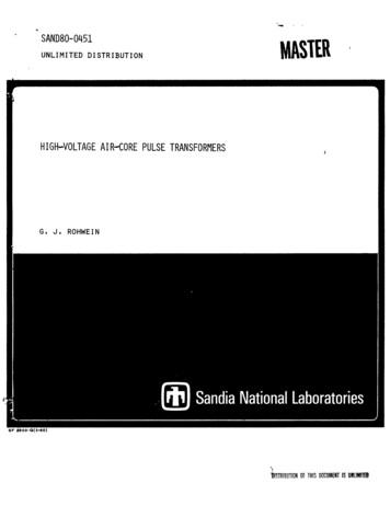
Application Guidelines for 12-Pulse Operation of PowerFlex 750-Series AC DrivesFor rectifier sizing, the worst case pre-existing distortion assumed is 3% of 5thharmonic distortion and 1% voltage unbalance. This results in worst case currentsharing of 65%:35%. For example, if the total RMS AC input current for thedrive is 100 A with 6-pulse input, each rectifier bridge must be sized for 65 A.Current unbalance as a function of pre-existing voltage unbalance and distortionis shown in Figure 16 for the 12-pulse configuration of Frames 6 10 with DCinput. The line reactor is required to ensure low ripple on the DC bus of the DCinput drives and to balance the currents between the rectifier bridges when theinput voltages are unbalanced or have significant harmonic distortion.If the drive’s RMS AC input current for 6-pulse operation is Iline 6P (For driveinput current ratings, see the PowerFlex 750-series AC Drives Technical Data,publication 750-TD001), then the line reactor inductance (LAC) required isdetermined as follows, where VLL is the AC RMS voltage of each secondarywinding and fline is the line frequency:0.03 AC ( ) 106 LL3 0.5 2 ƒ line 6Current Unbalance (%)Figure 16 - Current Unbalance with AC Line ReactorVoltage distortion at the primary side of the transformer can vary fromapproximately 4% THD with utility source to about 10% THD with generatorsource (typical impedance of 25%). This must be considered for other loadsconnected at the point of common coupling (PCC1 in Figure 1 on page 3 andFigure 2 on page 4).18Rockwell Automation Publication 750-AT003A-EN-P - March 2014
Application Guidelines for 12-Pulse Operation of PowerFlex 750-Series AC DrivesTransformer Sizing and SpecificationsTransformer kVA rating is based on worst case current unbalance between thedelta and wye secondary windings.Given that the drive’s input AC RMS current for 6-pulse input is Iline 6P andwith the worst case unbalance of 65:35 between the two rectifier bridges, thetotal kVA rating of the transformer is determined as follows. The AC RMSvoltage of each secondary winding is VLL. Since each secondary winding carries6-pulse currents, an appropriate de-rating factor is applied:kVATransformer 1.113 LL ( 2 0.65 1000line 6) 1.4313 LL1000line 6Further, the open circuit voltage of the secondary windings must be matched.The impedance of the transformer must be between 4 6%. The K-factor of thetransformer must be greater than 6 to handle the harmonic currents.The selection of PowerFlex SCR bus supplies for true 12-pulse operation ofPowerFlex 750-Series, frames 6 10 drives, along with Bulletin 1321 line reactorcatalog numbers and minimum transformer kVA is provided in PowerFlex SCRBus Supply Selection Chart for 12-pulse Operation of PowerFlex 750-Series,Frames 6 10 Drives on page 21.Electrostatic Shielding:If the voltage on the primary side of the transformer is greater than twice thesecondary voltage, an electrostatic shield between the primary and secondarywindings is strongly recommended to prevent transients on the high voltage sidefrom propagating to the secondary windings. An electrostatic shield reduces thecapacitive coupling between the primary and secondary, and must be tied toground. In addition, it is also recommended that the neutral of the wye secondarywinding be solidly grounded. However, high resistance grounding with properchoice of resistance value to limit secondary transient voltage to ground is alsoacceptable. For quasi 12-pulse systems, the delta winding must be solidlygrounded or high resistance grounded using a grounding transformer.Rockwell Automation Publication 750-AT003A-EN-P - March 201419
Application Guidelines for 12-Pulse Operation of PowerFlex 750-Series AC DrivesThe recommended method for fusing and transient overvoltage protection isillustrated in Figure 17. The AC line fuses, typically high speed semiconductorfuses, should be integral to the rectifier bridge and are intended for short circuitprotection of the rectifier power device. PowerFlex SCR bus supplies have ACfuses (on the 400 A and 600 A units, the fuses are on the AC line; on the 1000 Aunit, the fuses are in series with each SCR device). If the rectifier bridge includesan integral capacitor bank, DC bus fuses should be placed after the capacitorbank and before the interconnection to the system DC bus, to prevent faultsfrom cascading. PowerFlex SCR bus supplies do not have integral capacitorbanks; however, the units rated at 400 A and 600 A have integral DC fuses,whereas the 1000 A unit does not have DC fuses.Fusing, Transient Overvoltage Protection andCommon-Mode JumperRecommendationsMetal oxide varistors (MOV) are used for transient overvoltage protection andshould be part of the rectifier power structure. PowerFlex SCR bus supplies haveintegral MOVs.Fuses or circuit breakers should be used for branch circuit protection, withratings in accordance with the NEC in the United States or local electrical codesas applicable. This is to protect each transformer secondary winding and thecabling to the rectifier bridge from overloads and short-circuits. The currentrating to use for selection of the branch circuit protective device is 0.65Iline 6P,where a 65%:35% split is assumed for current sharing between the two rectifierbridges, and Iline 6P is the drive’s rated input RMS current for 6-pulse operation.If the secondary wye winding of the transformer is not solidly grounded, then anycommon mode capacitor networks on the AC line or DC bus (on both therectifier bridges and the drives on the DC bus), and the MOVs must bedisconnected from ground. For instructions on how to disconnect the MOVsand common mode capacitors, see the PowerFlex SCR Bus Supply User Manual,publication 20S-UM001, and the PowerFlex 750-Series AC Drives InstallationInstructions, publication 750-IN001.To achieve compliance with the EMC directive of IEC, the AC system must besolidly grounded at the wye secondary and the common mode capacitornetworks must be connected to ground.Figure 17 - 12-pulse Drive Branch Circuit Protection, Fusing and Transient Overvoltage ProtectionFuseFuseBranch CircuitProtectionMOVFuseFuseMOV20Rockwell Automation Publication 750-AT003A-EN-P - March 2014
Application Guidelines for 12-Pulse Operation of PowerFlex 750-Series AC DrivesPowerFlex SCR Bus SupplySelection Chart for 12-pulseOperation of PowerFlex 750Series, Frames 6 10 DrivesTable 1 Table 4, beginning on page 22, provide the PowerFlex SCR bus supplyand Bulletin 1321 line reactor catalog numbers, ratings for input branch circuitprotection devices, and the kVA rating of the delta-delta-wye transformer for usewith PowerFlex 750-Series, frame 6 10 drives.The ratings specified in the tables are based on maximum voltage unbalance of1% and 5th harmonic distortion of 3%, which is a conservative estimate of worstcase power quality. However, if the voltage unbalance or harmonic distortionexceeds these values, then the current unbalance between the rectifier bridges willexceed the assumptions made in Table 1 Table 4, requiring higher current ratingfor the rectifier, transformer and branch circuit protective device. Please contactRockwell Automation Technical Support for assistance in sizin
6-pulse and 12-pulse drives is about 6 and 2 respectively, while it is nearly equal to the ideal value of 1 for 18-pulse drives. Background voltage distortion and unbalance will affect this significantly, particularly for 12-pulse and 18-pulse drives that require special phase-shifting tr