Transcription
Digital Transmission(Line Coding)EE4367 Telecom. Switching & TransmissionProf. Murat Torlak
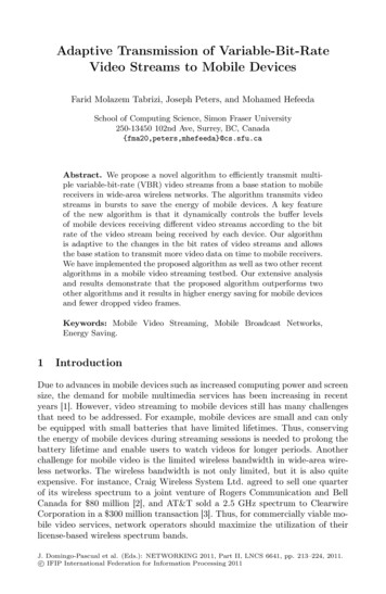
Pulse Transmission Source Multiplexer Line Coder Line Coding: Output of the multiplexer (TDM) is coded intoelectrical pulses or waveforms for the purpose oftransmission over the channel (baseband transmission) Many possible ways, the simplest line code on-off All digital transmission systems are design around someparticular form of pulse response.Nonreturn-to-zero (NRZ)Return-to-zero (RZ)EE4367 Telecom. Switching & Transmission(a)(b)(c)(d)(e)On-off (RZ)Polar (RZ)Bipolar (RZ)On-Off (NRZ)Polar (NRZ)Prof. Murat Torlak
Pulse Transmission over a ChannelEE4367 Telecom. Switching & TransmissionProf. Murat Torlak
Desirable Properties for Line Codes Transmission Bandwidth: as small as possible Power Efficiency: As small as possible for given BW andprobability of error Error Detection and Correction capability: Ex: Bipolar Favorable power spectral density: dc 0 Adequate timing content: Extract timing from pulses Transparency: Prevent long strings of 0s or 1sEE4367 Telecom. Switching & TransmissionProf. Murat Torlak
Review: Energy and Power Signals An energy signal x(t) has 0 E for average energy A power signal x(t) has 0 P for average powerCan think of average power as average energy/time.An energy signal has zero average power.A power signal has infinite average energy.Power signals are generally not integrable so don’t necessarilyhave a Fourier transform. We use power spectral density to characterize power signals thatdon’t have a Fourier transform. EE6390 Intro. to Wireless Comm. SystemsProf. Murat Torlak
Review: TimeTime-Invariant Systems Linear Time-Invariant Systems System Impulse Response: h(t) Filtering as Convolution in Time Frequency Response: H(f) H(f) ej H(f)x(t)h(t)x(t)*h(t)X(f)H(f)X(f)H(f)EE4367 Telecom. Switching & TransmissionProf. Murat Torlak
Review: Distortion Distortionless Transmission Output equals input except for amplitude scalingand/or delayx(t)h(t) Kδδ(t-ττ)H(f) Kej2ππfττX(f)Kx(t-ττ)Kej2ππfττX(f) Simple equalizers invert channel distortion Can enhance noise powerChannelX(f)H(f)N(f) Equalizer 1/H(f)X(f) N(f)/H(f)Prof. Murat Torlak
Review: Ideal Filters Low Pass FilterA-BB Band Pass FilterAA-B2-B1B1B2Prof. Murat Torlak
Power Spectral Density Power signals (P Energy/t) Distribution of signal power over frequencyX T ( w)T-T/202T/2X ( w)S x ( w) lim TT T2 Useful for filter analysisSx(f) H(f) 2Sx(f)H(f)For Sx(f) bandlimited [–B,B], B fcProf. Murat Torlak
Definition: Autocorrelation Defined for real signals as Rx(τ) x(τ)*x(-τ)1Rx (τ ) limT TT /2 x (t ) x (t τ )dt T / 2 Measures similarity of a signal with itself as afunction of delayRx(ττ)0τ Useful for synchronization: Rx(τ) Rx(τ) PSD and autocorrelation FT pairs: Rx(τ) Sx(f)Prof. Murat Torlak
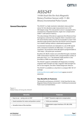
Bandwidth Usage of Line Codes Line codes are used for digital base-band modulation indata communication applications, Digital data stream is encoded into a sequence of pulses fortransmission through a base-band analog channel. The spectral properties of the line codes. We need a procedure for finding the PSD of line codesBinary DataSourcebkImpulseModulatorx (t ) akδ (t kT )kPulseFilter, f(t)y (t ) ak f (t kT )kLine CodingEE4367 Telecom. Switching & TransmissionProf. Murat Torlak
PSD Estimation We consider line coding pulses as a pulse train constructedfrom a basic pulse f(t) repeating at intervals of T with relativestrength ak for the pulse starting at t kT such that the kthpulse in this pulse train y(t) is akf(t-kT). For instance, the on-off, polar, and bipolar line codes are allspecial cases of this pulse train y(t), where a(k) takes on values0,1, or -1 randomly subject to some constraints. We can analyze the various lines codes from the knowledge ofthe PSD of y(t) Simplify the PSD derivation by considering x(t) that uses a unitimpulse response for the basic pulse of f(t).h(t) f(t)Sy(w) F(w) 2Sx(w)EE4367 Telecom. Switching & TransmissionProf. Murat Torlak
Power Spectral Density PSD is the Fourier Transform of autocorrelation Rectangular pulse and its spectrumEE4367 Telecom. Switching & TransmissionProf. Murat Torlak
PSD Derivation We now need to derive the time autocorrelation of a powersignal x(t) Since x(t) consists of impulses, Rx(τ) is found by where Recognizing Rn R-n for real signals, we haveEE4367 Telecom. Switching & TransmissionProf. Murat Torlak
PSD Derivation Since the pulse filter has the spectrum of F(w) f(t), wehave Now, we can use this to find the PSD of various line codes.EE4367 Telecom. Switching & TransmissionProf. Murat Torlak
PSD of Polar Signaling In polar signaling, binary “1” is transmitted by a pulse f(t) Binary “0” is transmitted by a pulse –f(t) In this case, ak is equally likely to be 1 or -1 and ak2 is always 1. There are N pulses and ak2 1 for each one. The summation on the right-hand side of the above equation is N. Moreover, both ak and ak 1 are either 1 or -1. So, akak 1 is either 1 or -1. They are equally likely to be 1 or -1 on the average, out of N terms the product akak 1is equal to 1 for N/2 terms and is equal to -1 for the remaining N/2 terms.EE4367 Telecom. Switching & TransmissionProf. Murat Torlak
Bipolar Signaling Bipolar signaling is used in PCM these days. A “0” is transmitted by no pulse A “1” is transmitted by a pulse f(t) or –f(t), depending onwhether the previous “1” was transmitted by –f(t) or f(t) With consecutive pulses alternating, we can avoid the dcwander and thus cause a dc null in the PSD. Bipolarsignaling actually uses three symbols [f(t),0,-f(t)], andhence, it is in reality ternary rather than binary signaling. To calculate the PSD, we haveEE4367 Telecom. Switching & TransmissionProf. Murat Torlak
PSD of Bipolar Signaling On the average, half of the ak’s are 0, and the remaining half areeither 1 or -1, with ak2 1. Therefore, To compute R1, we consider the pulse strength product akak 1. Four possible equally likely sequences of two bits:11,10,01,00. Since bit 0 encoded by no pulse (ak 0), the product, akak 1 0 forthe last three of these sequences. This means that, on the average,3N/4 combinations have akak 1 0 and only N/4 combinations havenon zero akak 1. Because of the bipolar rule, the bit sequence 11can only be encoded by two consecutive pulse of oppositepolarities. This means the product akak 1 -1 for the N/4combinations.EE4367 Telecom. Switching & TransmissionProf. Murat Torlak
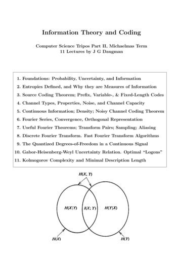
PSD of Lines Codes PSD of lines codesEE4367 Telecom. Switching & TransmissionProf. Murat Torlak
Binary NN-zero Substitution (BNZS) Bipolar signaling has several advantages: (1) its spectrumhas a dc null. (2) its bandwidth is not excessive. (3) it hassingle-error-detection capability. This is a due to the factthat if a single detection error is made, it will violate thealternating pulse rule. Disadvantages of bipolar signaling: it requires twice asmuch power (3 dB) as a polar signal. It is not transparent,i.e, we need a minimum density of 1’s in the source tomaintain timing at the regenerative repeaters. Low densityof pulses increases timing jitter. Solution: Binary N-zero substitution (BNZS) augments abasic bipolar code by replacing all trings of N 0’s with aspecial N-length code containing several pulses thatpurposely produce bipolar violations.EE4367 Telecom. Switching & TransmissionProf. Murat Torlak
BNZS Line Codes High Density Bipolar (HDB) coding is an example of BNZScoding format. It is used in E1 primary digital signal. HDB coding replaces strings of four 0’s with sequencescontaining a bipolar violation in the last bit position. Sincethis coding format precludes strings of 0’s greater than three,it is refereed to as HDB3 coding.000V and B00V, where B 1 conforms to thebipolar rule and V 1 violates the bipolarrule. The choice of sequence 000V or B00Vis made in such a way that consecutive Vpulses alternate signs in order to maintainthe dc null in PSD. B00V is used when there is an evennumber of 1’s following the last specialsequence 000V is used where there is an odd numberof 1’s following the last sequence.EE4367 Telecom. Switching & TransmissionProf. Murat Torlak
B3ZS Line Code B3ZS Algorithm (as used DS-3 signal interface): Each stringof three 0’s in the source data is encoded with either 00vor B0V.EE4367 Telecom. Switching & TransmissionProf. Murat Torlak
B8ZS Signaling B8ZS line code is used for T1 (DS1 signals) lines. It replacesany string of eight zeros in length with a sequence of 1’sand 0’s containing two bipolar violations. There are twobipolar violations in every substitution. Similarly, in B6ZS code used in DS2 signals, a string of sixzeros is replaced with 0VB0VB.EE4367 Telecom. Switching & TransmissionProf. Murat Torlak
Differential Encoding One limitation of polar signaling is that the signal for a 1 isexactly the negative of a signal for a 0. On manytransmissions, it may be impossible to determine the exactpolarity or an absolute phase reference. The decoder may decode all 1’s as 0’s or vice versa. Common remedy for the phase ambiguity is to usedifferential encoding that encodes a 1 as a chance of statesand encodes a 0 as no change in state. In this way, we donot need absolute phase reference.EE4367 Telecom. Switching & TransmissionProf. Murat Torlak
Differential Encoding The differentially encoded sequence {dk} is generated from theinput binary sequence {mk} by complementing the modulo-2 sum ofmk and dk-1. The effect is leave the symbol dk unchanged from theprevious symbol if the incoming binary symbol mk is 1, and to toggledk if mk is 0. The decoder merely detects the state of each signal interval andcompares it to the state of the previous signal. If changed occurred, a 1 is decoded. Otherwise, a 0 isdetermined.dk110110001dk001001110d k 111011000mk10010110EE4367 Telecom. Switching & TransmissionProf. Murat Torlak
Applications of Line Coding NRZ encoding: RS232 based protocolsManchester encoding: Ethernet networksDifferential Manchester encoding: token-ring networksNRZ-Inverted encoding: Fiber Distributed Data Interface(FDDI)EE4367 Telecom. Switching & TransmissionProf. Murat Torlak
Asynchronous vs SynchronousTransmission Asynchronous transmission: Separate transmissions of groups ofbits or characters The sample clock is reestablished for each reception Between transmissions an asynchronous line is in idle state. Synchronous transmission: Digital signals are sent continuously ata constant rate The sample clock is established and maintained throughout entiretime.EE4367 Telecom. Switching & TransmissionProf. Murat Torlak
Synchronization Consideration Problem of unvarying signal When a signal is unvarying, the receiver cannot determine thebeginning and ending of each bit. Take unipolar coding for example. A long uninterrupted seriesof 1s or 0s can cause synchronization problem. Problem of Using Timers Whenever there is no signal change to indicate the start of thenext bit in a sequence, the receiver has to rely on a timer. Givenan expected bit rate of 1000 bps, if the receiver detects apositive voltage lasting 0.005 seconds, it reads one 1 per 0.001seconds, or five 1s. However, five 1s can be stretched to 0.006second, causing an extra 1 bits to be read by the receiver. Thatone extra bit in the data stream causes everything after it to bedecoded erroneously. Problem of Having a Separate Clock Line A solution developed to control the synchronization of unipolartransmission is to use a separate, parallel line that carries a clockpulse. But doubling the number of lines used for transmissionincrease the cost.EE4367 Telecom. Switching & TransmissionProf. Murat Torlak
Synchronous CommunicationEE4367 Telecom. Switching & TransmissionProf. Murat Torlak
Asynchronous Transmission Bits are sent one character at a time. (A character is in general 8 bitsin length) Timing or synchronization must only be maintained within eachcharacter. The receiver has the opportunity to resynchronize at thebeginning of each new character. Start-stop technique Idle state: When no character is being transmitted the linebetween transmitter and receiver is in an “idle” state. Thedefinition of idle is by convention, but typically is equivalent tothe signaling element for binary 1. Start bit: The beginning of a character is signaled by a start bitwith a value of binary 0. Data bits Stop bit: The last bit of the character is followed by a stop bit,which is a binary 1. A minimum length for the stop bit is specifiedand this is usually 1, 1.5 or 2 times the duration of an ordinarybit. No maximum value is specified, Since the stop bit is thesame as the idle state.EE4367 Telecom. Switching & TransmissionProf. Murat Torlak
Asynchronous CommunicationEE4367 Telecom. Switching & TransmissionProf. Murat Torlak
Bandwidth Definitions Measures of Bandwidth (BW): 99% BW freq. range where 99% of power is Absolute BW : Range of frequencies over a non-zero spectrum Null-to-Null BW : Width of the main spectral lobe Half-power bandwidth: 3dB bandwidthHalf-power bandwidthdBEE6390 Intro. to Wireless Comm. SystemsProf. Murat Torlak
Pulse Shaping Pulse shaping concerns with how to shape a pulse p(t) inorder to achieve a desired Sy(w). The PSD Sy(w) is strongly and directly influenced by thepulse shape f(t) because Sy(w) contains the term F(w) 2. Typical pulse response of a bandlimited channelNyquist Pulse or Raised-Cosine pulse-2T –T 0 T 2T 3T1/Wsinc pulse-3/R -2/R -1/R1/R 2/R 3/R-WWEE4367 Telecom. Switching & TransmissionProf. Murat Torlak
Maximum Signaling Rate The percentage of total spectrum power is importantmeasure A major result for digital transmissin pertains to themaximum rate at which pulses can be transmitted over achannel. If a channel has bandwidth W, then the narrowest pulsethat can be transmitted over the channel has durationT 1/(2W) seconds. Thus, the maximum rate at which pulses can betransmitted through the channel is given by Rmax 2 W pulses/second.EE4367 Telecom. Switching & TransmissionProf. Murat Torlak
Multilevel Signaling Digital communications uses only a finite number of symbolsfor communication, the minimum being two (binary) Thus far, we have only considered the binary case. In some applications, the bandwidth is limited but higherdata rates are desired, number of symbols (i.e., voltagelevels) can be increased while maintaining the same signalingrate (baud rate). Multilevel signaling: The data rate R achieved by a multilevelsystem is given byMultilevel line codesMultilevel transmissionEE4367 Telecom. Switching & TransmissionProf. Murat Torlak
Multilevel Signaling and Channel Capacity Suppose we increase the number of levels while keepingthe maximum signal levels A fixed. Each increase in thenumber of signal levels requires a reduction in the spacingbetween levels. At some point, these reductions will implysignificant increases in the probability of detection errorsas the noise will be more likely to cause detection errors The channel capacity of a transmission system is themaximum rate at which bits can be transferred reliably.Shannon derived an expression for channel capacity of anideal low-pass channel. He showed that reliablecommunication is not possible at rates above this capacity.EE4367 Telecom. Switching & TransmissionProf. Murat Torlak
MultiLevel Signals and Noise Multilevel signaling and noiseEE4367 Telecom. Switching & TransmissionProf. Murat Torlak
Signal--toSignalto-Noise Ratio Definition of SNRsignalHighSNRtttnoisesignalLowSNRsignal noisenoisetsignal noisettSNR (dB) 10 log10 SNRA noise free sample voltage at the receiverσ2 the total noise power at the detector (N0)(NBW)NBW noise bandwidthN0 Power of white noise per HertzEE4367 Telecom. Switching & TransmissionProf. Murat Torlak
Error Performance Signal Detection: A decision of which signal was transmittedis made by comparing the measurement (at the appropriatetime) to a threshold located halfway between thesenominal voltages that represent “0” and “1”. Error performance depends on the nominal distancebetween the voltages and the amount of fluctuation in themeasurements caused by noise. In absence of noise, the measurement of the positive pulsewould be A and that of negative pulse would be –A. Becauseof noise, these samples would be A n where n is therandom noise amplitude. The error performance analysis in communication circuits istypically based on white Gaussian noise.EE4367 Telecom. Switching & TransmissionProf. Murat Torlak
Error Probabilities We now compute the probability of error for a polar signal.The amplitude n of the noise is Gaussian distributed. Itranges from - to according Gaussian PDF. When “0” is transmitted, the sample value of the receivedpulse is –A n. If n A, the sample value is positive and thedigit will be detected wrongly as 1. If P(error 0) is theprobability of error given that 0 is transmitted, then, Probability of error for a polar signalEE4367 Telecom. Switching & TransmissionProf. Murat Torlak
Twisted Pair A twisted pair consists of two wires that are twistedtogether to reduce the susceptibility to interference.Gauge (diameter) The two-wire system is susceptible to crosstalk and noisesince the multiple wires are bundled together.EE4367 Telecom. Switching & TransmissionProf. Murat Torlak
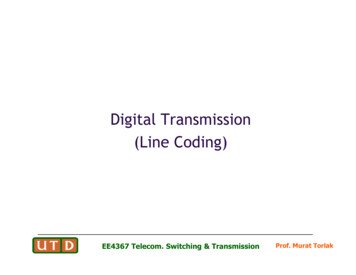
Error Performance Polar SignalingA Peak amplitude (Volts)σ noise rms amplitude (Volts)σ2 total noise powerPower A2 On-Off SignalingPower A2/2 Bipolar Signaling010PolarOn-OffBipolar-2Power A2/2SNR Power/σ2Probability of Error10-410-610-810012345678910Signal-to-Noise Ratio Power/σEE4367 Telecom. Switching & Transmission11121314152Prof. Murat Torlak
Performance Monitoring Redundancy Checks Parity Bits are inserted into DS3 and DS4 signals for thepurpose of monitoring the channel error rate. The following equation relates the parity error rate (PER) tothe channel probability of error or bit error rate (BER)N number of bits over which parity is generatedp BER assuming independent errors Cyclic redundancy check (CRC) codes are also incorporatedinto a number of transmission systems as a means ofmonitoring BERs and validating framing acquisition. Examples of CRC use: Extended superframe (ESF) on T1 linesN length of CRC field (including CRC bits)p BER assuming independent errorsEE4367 Telecom. Switching & TransmissionProf. Murat Torlak
PSD Estimation We consider line coding pulses as a pulse train constructed from a basic pulse f(t) repeating at intervals of T with relative strength a k for the pulse starting at t kT such that the k th pulse in th