Transcription
Seawater Air Conditioning: A Basic UnderstandingIntroductionSeawater Air Conditioning (SWAC) is an alternate-energy system that uses thecold water from the deep ocean (and in some cases a deep lake) to cool buildings. Insome areas it is possible to reduce dramatically the power consumed by airconditioning (AC) systems; SWAC can be a cost-effective and attractive investment. Itis an alternate energy for air conditioning.This paper is an introduction to Seawater Air Conditioning; it describes thebenefits, the technology, the areas best suited for this form of energy, some exampleprojects, the economics and the key components of the systems.Benefits of a SWAC SystemThe Seawater Air Condition Systems taps into a significant and highly valuablenatural energy resource that is available at some coastal locations. The benefits of aseawater air conditioning system include: Large energy savings approaching 90%Proven technologyShort economic payback periodEnvironmentally friendlyCosts are nearly independent of future energy price increases.No evaporative water consumption.Cold seawater availability for secondary applications.Conventional Air Conditioning BasicsThe schematic to the rightillustratesaconventionalairconditioning system for a largebuilding. A constant flow of cold freshwater is circulated throughout thebuilding(sometimesmultiplebuildings) for heat removal. As thischilled water moves throughout thebuilding and absorbs heat, itstemperature rises from an incomingvalue of approximately 7-8ºC to anoutflow value approximately 5ºChigher. This warmer water thenenters the chiller.Seawater Air Conditioning20041Makai Ocean Engineering, Inc.Makai@makai.com
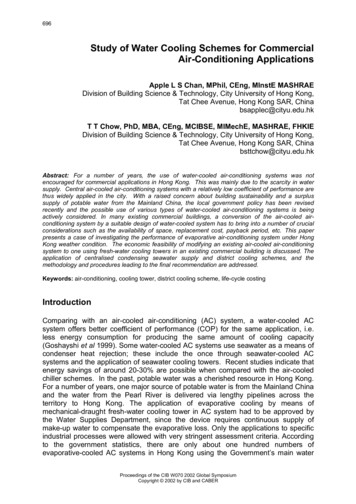
The chiller is a refrigeration system that cools the recirculation water. Waterenters the chiller at a nominal 12-13 C and exits at 7-8 C. The chiller consumeselectricity as it "pumps" heat from a cold source to a warmer source. The total heatremoved from the building and the electrical power consumed by the chiller passesthrough the chiller's condenser to a heat sink. The most conventional means ofeliminating this excess heat is to use a cooling tower that dumps the heat into theatmosphere primarily through evaporative cooling. Cooling towers consume freshwater; some chillers are air cooled if fresh water is not economically available.The energy requirements for a large building's air conditioning system aresignificant and, depending upon the location, may be the dominant electrical load ofthe building. The electrical requirement for conventional chiller operation and cooling is0.9 to 1.3 kW/ton depending upon the location, cooling system, and age of the system.Seawater Air Conditioning ConceptsAlong many ocean coastlines and lake shorelines, there is reasonable accessto naturally cold water that is as cold or colder than the water used in conventional airconditioning systems. If this water can be tapped, then the significnat power foroperating mechanical chillers to keep the chilled water cold can be eliminated.Temperature Profile323028Temperature, deg C.262422201816141210864200200400600800Depth, meters10001200The adjacent temperature profileillustrates the temperature vs depth that istypical for the world’s tropical deep oceans inthe summertime: 7 C or below can bereached at 700m depth, 5 C. or below at1000m. The deep-water portion of this profilechanges little seasonally and therefore coldwater is available on a year round basis. Inmore northern climates, very cold water canbe reached at shallower depths during thesummer – in both oceans and in deep waterlakes.The basic concept of seawater air conditioning is to take advantage of availabledeep cold seawater to cool the chilled water in one or more buildings as opposed tousing more energy intensive refrigeration systems.A seawater air conditioning system is illustrated below. The buildings to the farright are identical internally to buildings cooled with conventional A/C. Chilled freshwater moves through these buildings with the same temperatures and flows ofconventional systems. The seawater and chilled water pumps and heat exchangerswould typically be located at the shoreline in a cooling station.Seawater Air Conditioning20042Makai Ocean Engineering, Inc.Makai@makai.comai.com
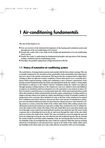
The main components of a seawater air conditioning system are the seawatersupply system, the heat exchanger or cooling station and the fresh water distributionsystem. These basic components can be optimized for each specific location, climateand building.This schematic is an alternate view of a basic centralized seawater airconditioning system. The chilled water loop is fresh water and operating at the sametemperaturesaswithconventional AC. The interiorof the building is unchangedwith SWAC systems. Thechilled water is kept coolthrough a heat exchangerwith a counter flow of deepcold seawater. The heatexchanger is titanium toeliminatecorrosionandfouling does not occurbecause of the purity of thedeep seawater. Seawater isbrought to the site through adeep-waterpolyethylenepipeline. These pipelinesreach out several kilometersoffshore and have a nominal intake depth of 700 m. The effluent seawater isdischarged though a second pipe at a depth of approximately 40 m.Seawater Air Conditioning20043Makai Ocean Engineering, Inc.Makai@makai.com
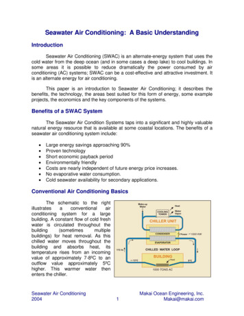
Seawater air conditioning is not technically complex nor is it a high technicalrisk. It is established technology being applied in an innovative way. All thecomponents necessary exist and have been operated under the conditions required.Use of an AuxiliaryChiller: In some cases, it iseither too costly or impractical tosupplyseawateratthenecessary low temperatures tomaintain minimum temperaturesin the chilled water loop. Thedistance offshore to reachsufficiently cold water might beprohibitive or the ocean depthmay simply not be available. It issometimeseconomicallypossible to use auxiliary chillersto supplement the coolingprovided by the seawaterexposure. This is illustrated below. The fresh chill water is first cooled by seawaterthrough a heat exchanger and then secondarily cooled with an auxiliary chiller. Theauxiliary chiller is basically a refrigeration system with its condenser cooled by thereturning flow of cool seawater. With the condenser kept cool, the auxiliary chiller canoperate at an extremely high efficiency – as high as double that of a conventionalchiller.Cold Storage: A SWAC system has a high capital cost and a low operatingcost. The peak capacity of the system must match the peak demand of the buildingsthat it serves. These demands are not constant throughout the day or throughout theyear, and the total system is frequently not being used to its maximum capacity.Therefore, capital dollars are spent on a system that may not always be used to itsmaximum potential. A means of minimizing the capital cost is to use cold-waterstorage. The seawater air conditioning system would be operated 100 percent of thetime and when the building demands are low, the excess capacity is directed into astorage system of cold fresh water. When A/C demand is at its peak, the cold water isdrained from its storage to meet the demand.Cold water storage tanks are commercially available that are constant volume;the warm water remains at the top and the coldest water remains at the bottom. Thesetanks are now used in conjunction with conventional A/C systems to take advantage oflow, off-peak electrical rates.Seawater Air Conditioning20044Makai Ocean Engineering, Inc.Makai@makai.com
Environmental AspectsA SWAC system has significant environmental benefits: These include drasticreductions in electricity consumption which reduces air pollution and greenhouse gasproduction, and substitution of simple heat exchangers for chiller machinery whichoften use ozone-depleting chlorofluorocarbons (CFCs).The existence of the deep ocean heat sink results from natural climaticprocesses where water is cooled at the poles, becomes dense and sinks to deeperwater and slowly moves toward the equator. The cold ocean is therefore both immenseand renewable.Return water from a SWAC system can be handled in a number of ways.Typically it is returned to the ocean at a location where the return water temperaturenearly matches the ambient water.There are significant secondary applications for this seawater. Secondarycooling, aquaculture, desalination and even agriculture can benefit from the coldseawater. Aquaculturists value the water because it is clean and disease free. Whenused in conjunction with a warm source of water, they can have any temperatureseawater their product needs. Secondary cooling can be used in greenhouses andother locations where humidity control is not a major factor. Finally, research in Hawaiihas shown that even an arid land can be made highly productive with low fresh waterconsumption by cooling the soil and the roots of many tropical and non-tropical plants.Deep seawater is also desalinated and sold as a premium drinking water in the orient.Economic ViabilityThe economic viability of a SWAC system is site specific. Each location hasunique opportunities as well as problems. The main factors influencing the economicviability of a specific location include: The distance offshore to cold water: shorter pipelines are more economicalthan long pipelines.The size of the air conditioning load: there is an economy of scale associatedwith SWAC – systems less than 1000 tons are more difficult to justifyeconomically,The percent utilization of the air conditioning system: The higher the utilizationthroughout the year, the higher the direct benefits.The local cost of electricity: A high cost of electricity makes conventional ACmore costly and SWAC, in comparison, more attractive. Any cost analysisshould include current and future costs of electricity.The complexity of the distribution system on shore: SWAC works best with adistrict cooling arrangement, where many buildings are cooled takingSeawater Air Conditioning20045Makai Ocean Engineering, Inc.Makai@makai.com
advantage of the economy of scale. SWAC is even more economical if thisdistribution system is compact.Scenario A1, Levelized cost,Conventional vs SWAC3500Levelized e adjacent figure illustrates thedifference in lifetime costs for a conventionalAC system and a typical SWAC system. Thecosts are broken down into capital, operating(energy) and maintenance. The primary cost ofa SWAC system is in the initial capital cost. Theoperating and maintenance costs are small. Fora conventional AC system, the primary cost isin the power consumed over its lifetime. Hence,SWAC systems are ideal for base load AC thathas high utilization and conventioal AC may bebetter for situations of infrequent use.0A1 SWACA1 ConvIt’s important to note that there is a dramatic economy of scale as the size of thepipeline increases. The reason is that the cold water pipe costs per liter of waterdelivered decreases as the pipeline size increases and temperature rise via largepipelines is practically negligible. The figure to the right illustrates five SWAC scenariosof varying overall size; the two bars compare the life time cost difference betweenconventional AC and SWAC.Seawater Air 001,50015001,0001000500Peak Tons A/C20-year Levelized A/C cost comparisonsUS Dollars/ton/yearMakai has performed SWACfeasibility studies of a variety of sites.Typical results are that electricalconsumption is reduced by 80 to 90percent. Simple payback can befrom three to seven years, and longterm costs can be half that of aconventional air conditioning system.Not all locations, however, are ideal.Some have poor access to deepcold-water sources or the overallsize is too small to be economical.Each site is unique.500001234Scenarios Studied5SWACConv. A/CPeak Tons6Makai Ocean Engineering, Inc.Makai@makai.com
SWAC HistoryThe feasibility of using cold seawater to directly cool buildings has been studiedand analyzed for many years. At certain locations, successful installation and operationhas occurred. The following is a brief recent history of seawater air conditioning:In 1975, the US Department of Energy funded a program entitled "Feasibility ofa District Cooling System Utilizing Cold Seawater." [Hirshman et al] Several locationswere studied and the two most favorable sites were Miami/Ft. Lauderdale andHonolulu. The study, however, noted that one of the limiting technical factors was theinability to deploy large diameter pipelines to depths of 1500' and more. This technicalchallenge has since been addressed and demonstrated with Makai-designed deepwater pipelines at the Natural Energy Laboratory of Hawaii, Keahole Point, Hawaii.In 1980, the Naval Material Command at Port Hueneme, California, conducteda study entitled : "Sea/Lake Water Air Conditioning at Naval Facilities." [Ciani].Computer models were developed which provided reasonable estimates of the capitalcost and energy use of seawater air conditioning systems at Point Mugu, Californiaand Pearl Harbor, Hawaii. The study concluded that: at a hypothetical typical Navyfacility, a SWAC system will use 80% less energy than conventional A/C, but thecapital costs of SWAC systems are 60% greater. The Life Cycle Cost of SWAC at atypical Naval facility would be 25% lower than the life cycle cost of conventional A/C.In 1986, a joint project between the Canadian government and Purdy's WharfDevelopment, Ltd. demonstrated the use of ocean water as a source for buildingcooling to a 350,000 square ft. office complex along the waterfront in Halifax, NovaScotia. Due to the geographic conditions and annual low water temperatures, a smalldiameter pipeline was deployed to a depth of less than 100' ft. This was a major factorin limiting the overall expense of installing the cooling system. Total investment for thisproject was 200,000. The project was very successful and savings were identified inthe following areas: a saving of 50-60,000 per year in avoided electrical cost, fewermaintenance staff, reduction in fresh water, savings in water treatment, and savings incooling tower maintenance and replacement. The financial result in terms of a simplepayback period was two years. [Building Cooling] Today, Purdy's Wharf continues toutilize successfully an expanded seawater air conditioning system for their waterfrontproperties.In 1986, the Natural Energy Laboratory of Hawaii Authority, Keahole Point,Hawaii began the successful utilization of SWAC in their main laboratory building.Deep-water pipelines were already installed to provide cold, nutrient rich, seawater forresearch purposes in alternate energy and aquaculture. Since a cold water supply wasalready incorporated into the infrastructure, it was decided to utilize the cold water forcooling. This proved to be a very sound economic decision that resulted in monthlyelectric savings of 400. Today, the use of SWAC has been expanded to a newadministration building and a second laboratory. Estimated monthly saving in electricityis 2000.Seawater Air Conditioning20047Makai Ocean Engineering, Inc.Makai@makai.com
In 1990, the US Department of Energy funded a study entitled: "Waikiki DistrictCooling Utility." The purpose of this brief study was to evaluate whether it waseconomically and technically feasible to utilize seawater air conditioning as a means toprovide cooling to the hotels in Waikiki and to create a Waikiki Cooling Utility. Waikikiwas targeted because of the high density of hotels, high electrical consumption and alarge demand for air conditioning. It was estimated by Hawaiian Electric Company thatof the 107 Megawatts consumed in Waikiki, 51.4 Megawatts were used for airconditioning. This study concluded that economically and technically, Waikiki could becooled by utilizing seawater air conditioning.In 1995, Stockholm Energy started supplying properties in central Stockholmwith cooling from its new district cooling system. Most of the cooling is produced byusing cold water from the Baltic Sea. The temperature of the cooling water leaving theplant is 6 C or lower and the return temperature from the distribution grid is 16 C athigh load and a few degrees lower at low load. The district cooling system is designedfor a maximum load of 60 MW.In 1999, the Cornell Lake Source Cooling Project installed a 63” diameterpipeline into nearby Lake Cayuga. This Makai-designed pipeline was 10,000‘ in lengthand installed to a depth of 250’. Cold water from this pipeline, at approximately 4 ,provides air conditioning for the Cornell University Campus. This system is capable ofproviding in excess of 20,000 tons of cooling; the system started operation in mid2000.In 2004, the Deep Water Cooling Project for Toronto, Canada, commencedcooling of downtown Toronto with a peak capacity of 58,000 tons. Three 63” pipelinesreach far into lake Ontario for both potable and cooling water for the city. Makaiassisted in the engineering of this project.In 2004, Makai completed the design for a 450 ton SWAC system in FrenchPolynesia for a major hotel. Construction is commencing.In 2004, a SWAC system design and planning is underway in the Caribbean for2500 tons AC for a complex of hotels, meeting centers and university.In 2004, a SWAC system design has commenced for very large SWAC systemsto service Honolulu, Hawaii.Seawater Air Conditioning20048Makai Ocean Engineering, Inc.Makai@makai.com
Offshore Pipelines - ExperienceThe key cost and risk component ofany SWAC system is the offshore pipeline.The lack of a low-cost methodology for theinstallation of these pipelines preventedSWAC development in the 1970’s and80’s. Today, the technology for thesuccessful installation of pipelines todepths of 3000’ and greater is available.Numerous deep water intake pipelineshave been installed – nearly all of theworld’s successful pipes have been Makaidesigns.All of the deep seawater intake pipelinesdesigned by Makai have used polyethylene as thepipeline material. Polyethylene has significantadvantages for these pipelines in that it is inert andwill neither corrode nor contaminate the water.Polyethylene lengths are heat fused together to forma long, continuous pipeline with joints that are asstrong as the pipeline itself. Polyethylene hasexcellent strength and flexibility and is buoyant inwater. These characteristics allow a great deal ofdesign flexibility and deployment ease. The wallthickness can be varied depending on strengthrequirements for deployment and operating suctionover the lifetime of the pipe.Makai's approach for a deep water pipe deployment is to minimize the time atsea. The pipeline is basically designed for the deployment process since thisrepresents the major cost and risk of the installation. The pipeline is assembledcomplete on shore, launched floating using the pipeline to support all anchors andfastenings, towed to the site, and controllably submerged while carefully monitoringpipe tensions and pressures. The procedure is stable and reversible.The major risk to the pipeline is during deployment. These are standard marineconstruction risks and would be covered by the installer’s insurance. Once deployed,the likelihood of deep-water failure is very remote.Installed Pipelines: Makai has been designing and working with deep waterpipelines since 1979 and has designed a number of down-the-slope polyethyleneintake pipelines and suspended pipelines. In addition, Makai has been involved with avariety of field research programs studying the installation and loading on largeSeawater Air Conditioning20049Makai Ocean Engineering, Inc.Makai@makai.com
diameter pipelines - both deep and shallow. A brief summary of Makai's experience inHDPE (High Density Polyethylene) deep water pipeline design, analysis anddeployment is summarized below:Lake Source Cooling:Cooling Makai wasselected by Gryphon InternationalEngineering Services and CornellUniversity to design a 63” diameterHDPE intake and a 48” diameter outfallpipeline in Cayuga Lake, NY to provide20,000 tons of centralized cooling for theuniversity. The intake pipeline is twomiles long with an intake at 250’ depth.The pipeline provides 32,000 gpm ofcold water and has a 75-year lifetime.Construction was completed in 1999.Toronto Pipelines: The city ofToronto is now operating a districtcooling system with a maximum capacityof 58,000 tons. The cooling is providedwith deep lake water from Lake Ontario.Makai assisted in the design of three,nearly 4 miles long, 63” diameter intakepipelines for this project.Indian OTEC Pipeline: Makai hasprovided conceptual designs and designguidance to the National Institute of OceanTechnology (NIOT) in Madras, India, for inOTEC intake pipeline and mooring systemfor a floating OTEC research barge in theIndian Ocean. This pipeline will be 1 meterin diameter and will provide water from a1000 meter depth.Seawater Air Conditioning200410Makai Ocean Engineering, Inc.Makai@makai.com.com
55", 3000’ deep Pipeline:PipelineMakai hasengineered the main seawater supply source for theHawaii Ocean Science Technology Park (HOSTPark) at Keahole Point, Hawaii. This supply systemconsists of a cold-water pipeline (55” diameter, 3000’deep, and two miles long), a 55” diameter warmwater intake pipe, a tunneled shoreline crossing anda shore-based pumping station. The system has thecapacity to deliver 27,000 gpm of 4 deg. C. waterand over 40,000 gpm of warm water to thetechnology park. Makai received a national awardfrom the American Society of Civil Engineers for thisproject as one of the six most outstanding CEprojects in 2003.40" Intake Pipeline Design andInstallation: In a project with R.M.Towill Corporation, funded by the Stateof Hawaii and the U.S. Department ofEnergy, Makai was tasked with thedesign of a 40" polyethylene cold waterpipe to be used jointly by the NaturalEnergy Laboratory and the HawaiiOcean Science and Technology(HOST) Park sites on the Big Island. Itis the largest deep-water intakepipeline in the world. This pipe is alarger and more rugged version of theprevious MOE 12" pipe design at NELH and includes a 3000' long buoyant section.Makai assisted in the deployment of this pipe to a depth of 2200' in August 1987. It iscurrently a main source of water for the Natural Energy Laboratory.18" Cold Water Pipeline: Makai designed andprovided construction management for an 18"down-the-slope cold-water intake at the NaturalEnergy Laboratory of Hawaii. The goal to install areliable, minimal cost, deep-water intake system to2000'. This polyethylene design differs from previousNELH pipelines in that the deep water pipe is buoyedapproximately 40' off the bottom on a series ofpendants, the deployment was accomplished withoutmajor offshore equipment. This pipeline wassuccessfully deployed in October, 1987, and is stilloperational.Seawater Air Conditioning200411Makai Ocean Engineering, Inc.Makai@makai.com.com
Long Operating OTECCold Water Pipeline:Makaiconceived,designedandmanaged the construction of anexperimental,down-the-slopepolyethylene OTEC pipeline, 12"in diameter, for the State ofHawaii. This one-mile longpipeline has an intake at 2000'and utilizes a unique 3000' longfree-floating catenary section toavoid contact with the steep, rockybottom. The pipeline was installed in 1981 off Keahole Point, Hawaii. In spite of its"temporary" design life of 2 years, it has survived many major storms including ahurricane and was operational for over twelve years.Mini-OTEC: Makai engineered severalportions of the Mini-OTEC project under contractto Dillingham Corp. This project was a fulldemonstration of Ocean Thermal EnergyConversion (OTEC) and jointly funded by theState of Hawaii, Lockheed, Dillingham and AlfaLaval. Makai designed a 2' diameterpolyethylene pipe that served not only as anintake pipe from a 2000' depth, but also as the"mooring line" for the 120' x 35' barge. The initialdesign for the barge layout, seawater intakes(cold and warm), effluent lines, and pumps wasalso done by Makai. Makai developed andplannedthedeploymentschemeandparticipated in the at-sea deployment. On August2, l979, Mini-OTEC developed 50 kW of powerand consumed 40 kW, for a net positive output ofl0 kW. This was the first time that a positive output had been achieved from any OTECfacility.French Polynesia: Makai hasengineered a complete SWAC systemfor a hotel in French Polynesia forsupplying 450 tons of AC. Thisdemanding project involved a 2000mlong pipeline going to 850m depth on aseabed with slopes up to 60 degrees.This project is underway in 2004.Seawater Air Conditioning200412Makai Ocean Engineering, Inc.Makai@makai.com.com
The basic concept of seawater air conditioning is to take advantage of available deep c A seawater air conditioning system is illustrated below. The buildings to the far right a would typically be located at the shoreline in a cooling station. ai.com Temperature Profile 0 2 4 6 8 10 12 14 16 18 20 22 24 26 28 30 32 0 200 400 600 800 1000 1200 .