Transcription
Official CertifiedSolidWorks Associate (CSWA)Examination GuideSolidWorks 2009SolidWorks 2010SolidWorks 2011The only authorized CSWA exam preparation guideBy David C. Planchard & Marie P. Planchard (CSWP)CD INSIDE:Model FilesSDCPUBLICATIONSFor the book’spractice tutorialsand more!www.SDCpublications.comSchroff Development Corporation
CHAPTER 3 - BASIC PART ANDINTERMEDIATE PART CREATIONAND MODIFICATIONObjectivesBasic Part Creation and Modification andIntermediate Part Creation and Modification are twoof the five categories on the CSWA exam. Thischapter covers the knowledge to create and modifymodels for these categories from detaileddimensioned illustrations.There are two questions on the CSWA exam in theBasic Part Creation and Modification category. Onequestion is in a multiple choice single answer formatand the other question (Modification of the model) isin the fill in the blank format. Each question is worthfifteen (15) points for a total of thirty (30) points.You are required to build a model, with six or morefeatures and to answer a question either on theoverall mass, volume, or the location the Center ofmass for the created model relative to the default partOrigin location. You are then requested to modifythe part and answer a fill in the blank formatquestion.There are two questions on the CSWA exam in theIntermediate Part Creation and Modificationcategory. One question is in a multiple choice singleanswer format and the other question (Modificationof the model) is in the fill in the blank format. Each question is worth fifteen (15) pointsfor a total of thirty (30) points. You are required to build a model, with six or morefeatures and to answer a question either on the overall mass, volume, or the location ofthe Center of mass for the created model relative to the default part Origin location. Youare then requested to modify the model and answer a fill in the blank format question.The main difference between the Basic Part Creation and Modification category and theIntermediate Part Creation and Modification or the Advance Part Creation andModification category is the complexity of the sketches and the number of dimensionsand geometric relations along with an increase in the number of features.Page 3 - 1
Basic and Intermediate Part CreationOn the completion of the chapter, you will be able to: Read and understand an Engineering document used in the CSWA exam: Identify the Sketch plane, part Origin location, part dimensions, geometricrelations, and design intent of the sketch and featureBuild a part from a detailed dimensioned illustration using the following SolidWorkstools and features: 2D & 3D sketch tools, Extruded Boss/Base, Extruded Cut, Fillet, Mirror,Revolved Base, Chamfer, Reference geometry, Plane, Axis, Calculate the overallmass and volume of the created part, and Locate the Center of mass for thecreated part relative to the OriginThe complexity of the models along with the features progressively increasesthroughout this chapter to simulate the final types of models that would be provided onthe exam.FeatureManager names were changed through various revisions of SolidWorks.Example: Extrude1 vs. Boss-Extrude1. These changes do not affect the models oranswers in this book.Read and understand anEngineering documentWhat is an Engineering document? In SolidWorks apart, assembly or drawing is referred to as adocument. Each document is displayed in theGraphics window.During the exam, each question will display aninformation table on the left side of the screen anddrawing information on the right. Read the providedinformation and apply it to the drawing. Variousvalues are provided on each question.If you don’t find your answer (within 1%) in themultiple choice single answer format section - recheckyour solid model for precision and accuracy.Copy the corresponding CSWA Model Folderfrom the CD in the book that matches your release ofSolidWorks to your hard drive. Work directly fromyour hard drive on the tutorials in this book.Page 3 - 2
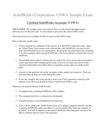
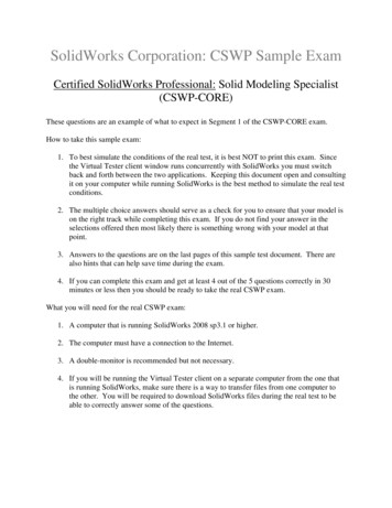
Basic and Intermediate Part CreationBuild a Basic Part from adetailed illustrationTutorial: Volume / Center of Mass 3-1Build this model. Calculate the volume of thepart and locate the Center of mass with theprovided information.1. Create a New part in SolidWorks.2. Build the illustrated dimensioned model.The model displays all edges onperpendicular planes. Think about the stepsto build the model. Insert two features:Extruded Base (Boss-Extrude1) andExtruded Cut (Cut-Extrude1). The partOrigin is located in the front left corner ofthe model. Think about your Base Sketchplane. Keep your Base Sketch simple.Given:A 3.30B 2.00Material: 2014 AlloyDensity .101 lb/in 3Units: IPSDecimal places 23. Set the document properties for the model.4. Create Sketch1. Select the Front Plane asthe Sketch plane. Sketch1 is the Basesketch. Sketch1 is the profile for theExtruded Base (Boss-Extrude1) feature.Insert the required geometric relations anddimensions.5. Create the Extruded Base feature. BossExtrude1 is the Base feature. Blind is the defaultEnd Condition in Direction 1. Depth 2.25in.Identify the extrude direction to maintain thelocation of the Origin.6. Create Sketch2. Select the Top right face as theSketch plane for the second feature. Sketch asquare. Sketch2 is the profile for the ExtrudedCut feature. Insert the required geometricrelations and dimensions.7. Create the Extruded Cut feature. SelectThrough All for End Condition in Direction 1.Page 3 - 3Origin
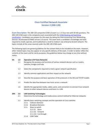
Basic and Intermediate Part Creation8. Assign 2014 Alloy material to the part.Material is required to locate the Center ofmass.9. Calculate the volume. The volume 8.28cubic inches.There are numerous ways to build themodels in this chapter. A goal is to displaydifferent design intents and techniques.Origin10. Locate the Center of mass. The location ofthe Center of mass is derived from the partOrigin. X: 1.14 inches Y: 0.75 inches Z: -1.18 inches11. Save the part and name it Volume-Centerof mass 3-1.12. Close the model.OriginThe principal axes and Center of massare displayed graphically on the model inthe Graphics window.Tutorial: Volume / Center of Mass 3-2Build this model. Calculate the volume ofthe part and locate the Center of masswith the provided information.1. Create a New part in SolidWorks.2. Build the illustrated dimensionedmodel. The model displays all edgeson perpendicular planes. Think aboutthe steps that are required to buildthis model. Remember, there arenumerous ways to create the modelsin this chapter.Given:A 100B 40Material: BrassDensity .0085 g/mm 3Units: MMGSOriginPage 3 - 4
Basic and Intermediate Part CreationThe CSWA exam is timed. Workefficiently.View the provided Part FeatureManagers.Both FeatureManagers create the sameillustrated model. In Option1, there arefour sketches and four features (ExtrudedBase and three Extruded Cuts) that areused to build the model.In Option2, there are three sketches andthree features (Extruded Boss/Base) thatare used to build the model. WhichFeatureManager is better? In a timedexam, optimize your time and use the leastamount of features through mirror, pattern,symmetry, etc.Use Centerlines to create symmetricalsketch elements and revolved features, or asconstruction geometry.OriginCreate the model using the Option2 PartFeatureManager.3. Set the document properties for themodel.4. Create Sketch1. Select the Top Plane as theSketch plane. Sketch a rectangle. Insert therequired dimensions.5. Create the Extruded Base feature. BossExtrude1 is the Base feature. Blind is thedefault End Condition in Direction 1.Depth 10mm.6. Create Sketch2. Select the back face of BossExtrude1.7. Select Normal To view. Sketch2 is the profilefor the second Extruded Boss/Base feature.Insert the required geometric relations anddimensions as illustrated.8. Create the second Extruded Boss/Base feature(Boss-Extrude2). Blind is the default EndCondition in Direction 1. Depth 20mm. Notethe direction of the extrude, towards the front of the model.Page 3 - 5Origin
Basic and Intermediate Part Creation9. Create Sketch3. Select the left face of Boss-Extrude1 asthe Sketch plane. Sketch3 is the profile for the thirdExtrude feature. Insert the required geometric relationsand dimensions.10. Create the third Extruded Boss/Base feature (BossExtrude3). Blind is the default End Condition inDirection 1. Depth 20mm.11. Assign Brass material to the part.12. Calculate the volume of the model. Thevolume 130,000.00 cubic millimeters.13. Locate the Center of mass. The location of the Centerof mass is derived from the part Origin. X: 43.36 millimeters Y: 15.00 millimeters Z: -37.69 millimeters14. Save the part and name it Volume-Center ofmass 3-2.15. Calculate the volume of the model using theIPS unit system. The volume 7.93 cubicinches.16. Locate the Center of mass using the IPS unitsystem. The location of the Center of mass isderived from the part Origin. X: 1.71 inches Y: 0.59 inches Z: -1.48 inches16. Save the part and name it Volume-Center ofmass 3-2-IPS.17. Close the model.There are numerous ways to create themodels in this chapter. A goal is to displaydifferent design intents and techniques.All SW models (initial and final) areprovided on the CD in the book. Copy the foldersand model files to your local hard drive. Do notwork directly from the CD.Page 3 - 6Origin
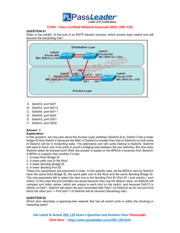
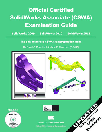
Basic and Intermediate Part CreationTutorial: Mass-Volume 3-3Build this model. Calculate the overallmass of the illustrated model with theprovided information.1. Create a New part in SolidWorks.2. Build the illustrated model. Themodel displays all edges onperpendicular planes. Think aboutthe steps required to build themodel. Apply the Mirror Sketchtool to the Base sketch. Insert anExtruded Base (Boss-Extrude1)and Extruded-Cut (Cut-Extrude1)feature.3. Set the document properties forthe model.Given:A 50, B 50, C 120Material: 6061 AlloyDensity .0027 g/mm 3Units: MMGSTo activate the Mirror Sketchtool, click Tools, Sketch Tools,Mirror from the Menu bar menu.The Mirror PropertyManager isdisplayed.4. Create Sketch1. Select the FrontPlane as the Sketch plane. Applythe Mirror Sketch tool. Select theconstruction geometry to mirrorabout as illustrated. Select theEntities to mirror. Insert therequired geometric relations anddimensions.OriginConstruction geometry isignored when the sketch is used tocreate a feature. Constructiongeometry uses the same line style ascenterlines.When you create a new part orassembly, the three default Planes(Front, Right and Top) are alignedwith specific views. The Plane you select for theBase sketch determines the orientation of the part.Page 3 - 7
Basic and Intermediate Part Creation5. Create the Boss-Extrude1 feature. Boss-Extrude1 is theBase feature. Apply the Mid Plane End Condition inDirection 1 for symmetry. Depth 50mm.6. Create Sketch2. Select the right face for the Sketch plane.Sketch2 is the profile for the Extruded Cut feature. Insertthe required geometric relations and dimensions. Applyconstruction geometry.7. Create the Extruded Cut feature. Through All is theselected End Condition in Direction 1.8. Assign 6061 Alloy material to the part.9. Calculate the overall mass. The overallmass 302.40 grams.10. Save the part and name it Mass-Volume 3-3.11. Close the model.Tutorial: Mass-Volume 3-4Build this model. Calculate the volume ofthe part and locate the Center of mass withthe provided information.1. Create a New part in SolidWorks.2. Build the illustrated model. The modeldisplays all edges on perpendicularplanes.OriginGiven:A 110, B 60, C 50Material: Nylon 6/10Density .0014 g/mm 3Units: MMGSPage 3 - 8Origin
Basic and Intermediate Part CreationView the provided PartFeatureManagers. Both FeatureManagerscreate the same model. In Option4, thereare three sketches and three features thatare used to build the model.In Option3, there are four sketches andfour features that are used to build themodel. Which FeatureManager is better?In a timed exam, optimize your designtime and use the least amount of features.Use the Option4 FeatureManager in thistutorial. As an exercise, build the modelusing the Option3 FeatureManager.3. Set the document properties for themodel.4. Create Sketch1. Select the Right Planeas the Sketch plane. Sketch1 is the Basesketch. Apply the Mirror EntitiesSketch tool. Select the constructiongeometry to mirror about as illustrated.Select the Entities to mirror. Insert therequired geometric relations anddimensions.5. Create the Boss-Extrude1 feature.Boss-Extrude1 is the Base feature.Blind is the default End Condition inDirection 1. Depth (A - 20mm) 90mm.Note the direction ofthe extrude feature.6. Create Sketch2. Selectthe Top face of BossExtrude1 for theSketch plane. Sketch2is the profile for thesecond ExtrudedBoss/Base feature(Boss-Extrude2).Insert the requiredgeometric relationsand dimensions.OriginPage 3 - 9
Basic and Intermediate Part Creation7. Create the Boss-Extrude2 feature. Blind is the defaultEnd Condition in Direction 1. Depth 30mm.8. Create Sketch3. Select theleft face of Boss-Extrude1for the Sketch plane. Applysymmetry. Insert therequired geometricrelations and dimensions.Use construction referencegeometry.The 20mm dimension forSketch3 was calculated by:(B - 40mm) 20mm.9. Create the Boss-Extrude3feature. Blind is the defaultEnd Condition in Direction 1. Depth 20mm. Note thedirection of Extrude3.10. Assign Nylon 6/10 material to the part.11. Calculate the volume. The volume 192,500.00 cubicmillimeters.12. Locate the Center of mass. The location of the Center ofmass is derived from the part Origin. X: 35.70 millimeters Y: 27.91 millimeters Z: -1.46 millimeters13. Save the part and name it Mass-Volume 3-4.14. Close the model.In the previous section, themodels that you createddisplayed all edges onPerpendicular planes and usedthe Extruded Base, ExtrudedBoss, or the Extruded Cutfeature from the Featurestoolbar.OriginIn the next section, buildmo
There are two questions on the CSWA exam in the Intermediate Part Creation and Modification category. One question is in a multiple choice single answer format and the other question (Modification of the model) is in the fill in the blank format. Each question is worth fifteen (15) points for a total of thirty (30) points. You are required to build a model, with six or moreFile Size: 1MBPage Count: 65