Transcription
Introduction to sheet metal forming processesINTRODUCTION TO SHEET METALFORMING PROCESSESThe documents and related know-how herein provided by SIMTECH subject tocontractual conditions are to remain confidential. This documentation and relatedknow-how shall not be disclosed, copied or reproduced by any means, in whole orin part, without the prior written permission of SIMTECH. 1999 SIMTECH. All rights reservedProduct names are mentioned for identification only and may be registeredtrademarks.SIMTECH37 rue des Acacias, 75017 ParisFRANCETel: (33) (1) 56 68 80 00Fax: (33) (1) 56 68 80 06Copyright 2001 SimTech Simulation et Technologie All rights reservedpage1/47
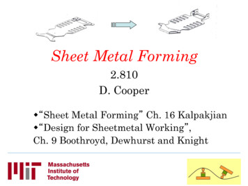
Introduction to sheet metal forming processesINTRODUCTION: EVOLUTION OF INDUSTRIAL STAMPINGBack in 1985, the development cycle of a stamped part looked more or less likethis (a sequential series of operations stemming from a single style design):STYLEDESIGNProcess Dev.Product Devpt.Product Design PP d tSoft/Hardtool builtSoft/Hardtool tryout42 monthsToday, people look at it rather as a sort of funnel, where key decisions are takenon the basis of different factors and alternative choices.style product-processtooling CAMdesignvalidationtryoutprocesproduction18 monthsCopyright 2001 SimTech Simulation et Technologie All rights reservedpage2/47
Introduction to sheet metal forming processesOVERVIEW: THE STAMPING SYSTEM AND STAMPING DESIGNLike all complex system, stamping can be decomposed in hardware and software.By hardware we mean factors that cannot be changed from one operation toanother. Conversely, by software we mean factors that the operator can change inorder to obtained the desired result : a part with a given quality.HARDWARESOFTWAREPressPress set-upToolsMaterialLubricationThe highlighted areas represent the components of the stamping design.Copyright 2001 SimTech Simulation et Technologie All rights reservedpage3/47
Introduction to sheet metal forming processesWhat is a stamping press ?A stamping press is a machine that houses the stamping tools (tooling) and carriesthem around according to the kinematics indicated by the user (process set-up).The knowledge of the press used for a stamping operation provides us with usefulclues regarding: Value and distribution of restraining forces Tool deformation caused by stamping forces Contact and/or gap between tools and blankHowever, we should recall that, at the moment when the die design is carried out,the press is usually not yet known, so that its characteristics are rather a factor ofnoise than a useful information. Therefore, it will be important to have a design thatis robust with respect to the press type.Copyright 2001 SimTech Simulation et Technologie All rights reservedpage4/47
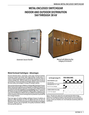
Introduction to sheet metal forming processesWhat is a stamping tool? What is process design?diedesign sign surfacePart as designed to fit in the car (after trimming)BlankholdersurfaceSurfaces that hold the blank before the formingoperation, including the restrainingProductionsurface/run-offsJunction between the two former surfaces,protecting the design surface and controllingmaterial flowDiefaceRun-offs blankholderProcess design is the ensemble of operations leading from the design geometry tothe dieface.Copyright 2001 SimTech Simulation et Technologie All rights reservedpage5/47
Introduction to sheet metal forming processesWhat is a stamping operation?A sheet formed part is usually obtained through a number of operation (phases)finalsurfaceintermediatesurfaceEach operation can be decomposed in several phases. It may be necessary tomodel each of them Gravity fall Holding Forming Trimming, flanging SpringbackMost problems in sheet metal forming come from a bad control of holding,restraining and springback.Gravity fallThe blank adapts to the blankholder shapeoriginal flat blankgravity deformed blankBLANKHOLDERPUNCHHoldingThe die pushes on the blankholder and squeezes the blankCopyright 2001 SimTech Simulation et Technologie All rights reservedpage6/47
Introduction to sheet metal forming processesPUNCHHolding controls the shape of the blank and the contact between the blank and thepunch.FormingThe die goes down until it squeezes the blank onto the punchCopyright 2001 SimTech Simulation et Technologie All rights reservedpage7/47
Introduction to sheet metal forming processesThe forming operation can in turn be divided in two parts:First the volume of the part is created:this is mostly controlled by theproduction surface and by therestraining systemLast the geometry details are formed:this is controlled by the geometry of thepartTrimming and springbackPlastic deformation leaves some stresses locked through metal thickness. Afterthe extraction from the tools these stresses are released originating a differentshape than that of the tools.Springback before trimming is sometimes important for the design of the tools androbots of the press.Springback after trimming may change the shape of the part to the point that it isimpossible to assemble.Copyright 2001 SimTech Simulation et Technologie All rights reservedpage8/47
Introduction to sheet metal forming processesSTAMPING PROCESS DESIGNDeliverables of process designDieface designDelivered in drawing or, most oftennowadays, CAD format.Dieface design specifies the geometryof the dieface for each of the stationsconsidered.Cutting patternCutting pattern profile is also delivered in drawing or CAD format. It specifies thegeometry of the punching tool prior to the actual stamping operation.Production constraints usually force the use of simple cutting patters. In practice,some basic shapes are used:rectangletrapezerectangle w/ cutsCopyright 2001 SimTech Simulation et Technologie All rights reservedrectangle w/ slotpage9/47
Introduction to sheet metal forming processesStamping cycleStamping cycle is the description of all the operations leading to the production ofthe finished stamped part. A typical stamping cycle includes: One or more stamping stations One coining station One trimming station One punching and flanging stationCopyright 2001 SimTech Simulation et Technologie All rights reservedpage10/47
Introduction to sheet metal forming processesDieface designThe simplified die addendum: basic geometry feature of the diefaceAlthough an actual dieface is a rather complicated system of surfaces, some basicgeometry features can be identified. Such basic features can be summarized asfollows : Stamping direction : identified onthe basis of minimum undercut,inertia moment or straightness ofprojected characteristic lines.punch radiusline Punch radius line : identified afterflange development and protection Die entry line : joins the punch lineto the blankholder, with an openingangle to avoid undercuts Blankholder : can be developable(conical or ruled) or quasidevelopable.Non-developableblankholders may give rise towrinkling problems during theholding phase.blankholderDie entry linestamping direction Otherrun-offscomponents.Typically, a dieface contains localelements (sausages) designed tocontrol punch/blank impact and/orto stretch locally the material.Copyright 2001 SimTech Simulation et Technologie All rights reservedpage11/47
Introduction to sheet metal forming processesHow many steps ?CoiningFlangingTrimming and springback reductionCopyright 2001 SimTech Simulation et Technologie All rights reservedpage12/47
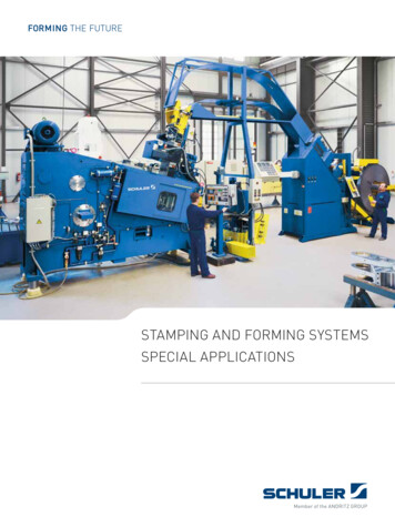
Introduction to sheet metal forming processesMATERIAL DEFORMATION DURING SHEET METAL FORMINGDeformation analysisPrincipal strain planeThe analysis of deformation in sheet metal forming is often based on the twoprincipal membrane strains ε1 and ε2.Most often, the maximum principal strain ε1 is positive in a forming operation.Hence, only half of the strain plane is considered (actually, three quarters).Deformation pairs relative to differentpoints of a stamped part are oftenplotted on such a half-plane.drawingexpansionε1This information can be drawn eitherfromFEsimulationorfromexperimental analysis (grids).The analysis of such deformation plotsgivesusefulinsightsintothemechanics of a forming operation.The deformation plot lends itself toseveral interesting considerations.Lines departing from the origin areequivalent to constant strain reexpansionε2Copyright 2001 SimTech Simulation et Technologie All rights reservedpage13/47
Introduction to sheet metal forming processesWe can identify:A line of pure expansion, whereε ε12A line of plane strain, whereε 01A line of plane stress, whereσ2 0A line of pure shear, whereε1 ε 2Further, based on the principle ofconservation of volume, lines at 45 ε ε12ε1 ε 3 ( cst.)representthickness.thelociofconstantFor each of these lines, the thinning t,ε2relative to the initial thickness t0 can be computed from basic rules of mechanics : tt ( ) 1 e ε1 ε 20Grid analysisCopyright 2001 SimTech Simulation et Technologie All rights reservedpage14/47
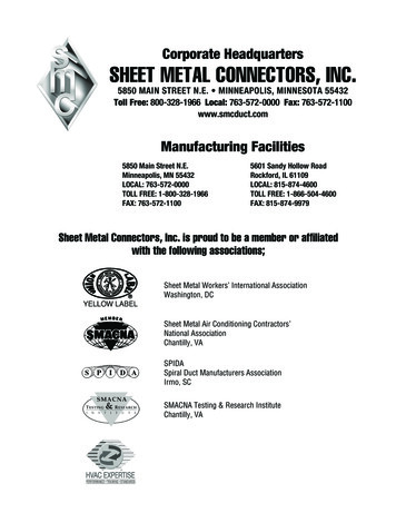
Introduction to sheet metal forming processesModes of deformationIn this chapter, we address the topic of material deformation, following the jargonof die engineers rather than of the mechanical engineers. The reader isencouraged to compare the deformation modes described here and in thepreceding chapter.DefinitionIn sheet metal forming practice, we distinguish five basic modes of deformation: STRETCHING: The material is expanded inboth directions. This mode of deformation isfound mostly on smooth bottoms of shallowparts and in hydroforming processes. DRAWING: This mode is typical thematerial flow from the flange towards theinner part of the die. BENDING/UNBENDING: This is a cyclicdeformation (most often associated withplane strain). It is found on the die entry lineas well as in drawbeads. STRETCH-AND-BEND: This mode isassociated to flanging operations for whichthe bending line is concave. COMPRESSION-AND-BEND: This mode isassociated to flanging operations for whichthe bending line is convex.l0l1l0l1Copyright 2001 SimTech Simulation et Technologie All rights reservedpage15/47
Introduction to sheet metal forming processesCorrelation between deformation modes and geometryRemember:The designer thinks intermofgeometricalfeatures: wall, angel,flanges, etc.Upper surfacewallwallangleflange. but the die engineersees the part as acollection of areas, oftenquite well alexpansion -bendcompression-benddrawingCopyright 2001 SimTech Simulation et Technologie All rights reservedpage16/47
Introduction to sheet metal forming processesFACTORS CONTROLLING DEFORMATIONIn the following, several factors controlling the stamping operation are analyzed.However, it should be pointed out that a hierarchy exists among the differentfactors, which is partially echoed by the traditional product development workflow.In order of importance, we can thus identify:1. Part geometry2. Dieface (active tooling surface) geometry3. Material rheological properties4. Lubrication and restraining systemsCopyright 2001 SimTech Simulation et Technologie All rights reservedpage17/47
Introduction to sheet metal forming processesPart geometryIn order to appreciate the foremost importance of the part geometry with respect toall other factors influencing sheet metal forming, we should recall that a sheetmetal forming operation can always be,from the conceptual point of view,divided in two stages: A first stage where the volume of thepart is generated A second stage where thegeometrical details are formed(reverse drawing)In the first stage, deformation andmaterial flow are mostly controlled byrun-offs (die addendum or dieface).In the second stage, however, most of the deformation is due to local reversedrawing or stretching, on which die addendum has little or no impact. Most"unfeasible" parts present defects produced in this stage. The identification andthe correction of these problems, which can be achieved through the early use ofnumerical simulation, lead to anticipate the modifications, which can be made at amuch lower cost.The rear wall of the IVECO cabinrepresents a very interesting example.Here, all the problems encountered atthe die try-out stage have beenidentified on the base only of the partas designed analysis. On the otherhand, defects appear with the samecalculation (folds on the edge of thepart) which would have disappeared assoon as a run-off and a blankholdersurface were added.Copyright 2001 SimTech Simulation et Technologie All rights reservedpage18/47
Introduction to sheet metal forming processesTool geometryIf part geometry controls mainlydeformation in reverse-drawing areas,relatively far from the die edge, it canbe expected that tool geometry bemostly important in deep-drawn areasaround the part boundary. As it alwayshappens with complicated problems,this statement is dangerous togeneralize but can be found true inmany occasion.For the RENAULT LAGUNA's enginesupport, the first proposition ofblankholder (flat surface) yields verylarge strains in an area wheresubsequent flanging produces rupture.The modification of the dieface (curvedblankholder surface) allows for a moreeven drawing depth along the partcontour. Part thinning is halved (from20% to 10%), though using less metalsheet, thanks to a removal of anexcessive run-off.At last, run-offs around the problemarea can also be improved, via the use of evolutionary radii instead of constantradii. This leads to a further decrease in thinning (down to 8% for the casestudied).Other examples of run-offs geometry are die entry radiusINSERER DISCUSSION SUR COPPA DIEXCopyright 2001 SimTech Simulation et Technologie All rights reservedpage19/47
Introduction to sheet metal forming processesCutting patternThe profile of the initial blank has a great influence on the material flow, especiallyfo
In sheet metal forming practice, we distinguish five basic modes of deformation: STRETCHING: The material is expanded in both directions. This mode of deformation is found mostly on smooth bottoms of shallow parts and in hydroforming processes. DRAWING: This mode is typical the material flow from the flange towards theFile Size: 1MBPage Count: 47