Transcription
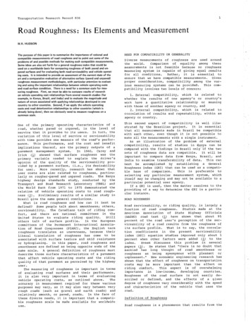
Fits, Tolerance and surface roughnessDefinitions of Terms:There are some important terms needed to know in tolerance dimension according to [ANSIY14.5M-1982] such as: Nominal Size: The designation that is used for the purpose of general identification is usuallyexpressed in common fractions. Basic Size or Dimension: The theoretical size from which limits of size are derived byapplication of allowances and tolerances, the basic size is the decimal equivalent to the nominalsize. Actual Size: The measured size of the finished part. Tolerance: The total amount by which a given dimension may vary, or the difference betweenthe maximum and the minimum. Limits: The maximum and minimum sizes indicated by a tolerance dimension. Allowance: The minimum clearance space (or maximum interference) intended between themaximum material condition (MMC) of mating parts. Allowance represents the tightestpermissible fit and is simply the smallest hole minus the largest shaft. For clearance fits, thisdifference will be positive, while for the interference fits it will be negative.Fig-1 Limit dimensions.Fits Between Mating Parts:Fit is the general term used to signify the range of tightness or looseness that may result from theapplication of a specific combination of allowances and tolerances in mating parts. [ANSI Y14.5M-1982]There are four general types of fits between parts. Clearance Fit: In which an internal member fits in an external member (as a shaft in a hole), andalways leaves a space or clearance between the parts. This space is the allowance, and in aclearance fit it is always positive. Interference Fit: In which the internal member is larger than the external member such thatthere is always an actual interference of metal. This interference is the allowance, and in aninterference fit it is always negative.DesignPage 1
Fits, Tolerance and surface roughness Transition Fit: In which the fit might result in either a clearance or interference condition, thesmallest shaft will fit in the largest hole with positive space, but the largest shaft will have to beforced in the smallest hole with an interference of metal (negative allowance). Line Fit: In which limits of size are so specified that a clearance or surface contact may resultwhen mating parts are assembled.Fig-2 Fits between parts.Basic Hole System:Toleranced dimensions are commonly figured on the so-called basic hole system which theminimum hole is taken as the basic size, an allowance is assigned, and tolerances are applied on bothsides of, and away from, this allowance.The basic hole size can be changed to the basic shaft size by subtracting the allowance for aclearance fit, or adding it for an interference fit. The result is the largest shaft size, which is now thebasic shaft.Basic Shaft System:This system should be used only when there is a reason for it, for example, it is advantageous whenseveral parts having different fits, but one nominal size are required on a single shaft. In this system,the maximum shaft is taken as the basic size, an allowance for each mating part is assigned, andtolerances are applied on both sides of, and away from, this allowance.The basic shaft size may be changed to the basic hole size by adding the allowance for a clearance fitor by adding the allowance for a clearance fit or subtracting it for an interference fit. The result is thesmallest hole size which is now the basic size.Fig-3 Basic hole and basic shaft system.DesignPage 2
Fits, Tolerance and surface roughnessSpecification of Tolerances:Several methods of expressing tolerances in dimensions are approved by [ANSI Y14.5M-1982] asfollows:1. Limit Dimensioning: the maximum and minimum limits of size and location are specified.2. Plus and Minus Dimensioning: the basic size is followed by a plus and minus expression oftolerance resulting in either a unilateral or bilateral tolerance. The unilateral system of tolerances: allows in only one direction from the basic size. The bilateral system of tolerances: allows variation in both directions from the basic size.3. Single-Limit Dimensioning: it is not always necessary to specify both limits. MIN or MAX isoften placed after a number to indicate minimum or maximum dimensions desired where otherelements of design determine the other unspecified limit.4. Angular Tolerances: are usually bilateral and in terms of degrees, minutes, and seconds.Fig-4 Plus and minus dimensioning.DesignPage 3
Fits, Tolerance and surface roughnessFig-5 Limit Dimensions.American National Standard Limits and Fits:It has issued the [ANSI B4.1-1967 (R1979)], “Preferred Limits and Fits for Cylindrical Parts”, definingterms and recommending preferred standard sizes, allowances, tolerances, and fits in terms of thedecimal inch.Specification of Fits:Letter symbols to identify the five types of fits are:RCRunning or Sliding Clearance FitsLCLocational Clearance FitsLTTransition Clearance or Interference FitsLNLocational Interference FitsFNForce or Shrink Fits Running and Sliding Fits: are intended to provide a similar running performance, with suitablelubrication allowance, throughout the range of sizes. The clearance for the first two classes,used chiefly as slide fits, increase more slowly with diameter than the other classes, so thataccurate location is maintained even at the expense of free relative motion. Locational Fits: are fits intended to determine only the location of the mating parts; they mayprovide rigid or accurate location, as with interference fits, or provide some freedom oflocation, as with clearance fits. Accordingly they divided into three groups: clearance fits,transition fits, and interference fits.DesignPage 4
Fits, Tolerance and surface roughness Force Fits: Force or shrink fits constitute a special type of interference fit, normallycharacterized by maintenance of constant bore pressures throughout the range of sizes. Theinterference therefore varies almost directly with diameter, and the difference between itsminimum and maximum value is small, to maintain the resulting pressures within reasonablelimits.Metric System of Tolerances and Fits:A system of preferred metric limits and fits by the International Organization for Standardization(ISO) is in the [ANSI B4.2-1978] standard.Fig-6 Terms related to Metric Limits and Fits [ANSI B4.2-1978].The following terms for metric fits are illustrated in the following: Basic Size: The size from which limits or deviations are assigned. Basic sizes, usually diameters. Deviation: The difference between the basic size and the hole or shaft size. (This is equivalentto the tolerance in the decimal-inch system). Upper Deviation: The difference between the basic size and the permitted maximum size ofthe part. (This compares with the maximum tolerance in the decimal-inch system). Lower Deviation: The difference between the basic size and the minimum permitted size of thepart. (This compares with the minimum tolerance in the decimal-inch system). Fundamental Deviation: The deviation closest to the basic size. (This compares with the minimum allowance in the decimal-inch system). Tolerance: The difference between the permitted minimum and maximum size of a part.DesignPage 5
Fits, Tolerance and surface roughness International Tolerance Grade (IT): A set of tolerances that varies according to the basic sizeand provides a uniform level of accuracy within the grade. For example, in the dimension 50 H8for a close-running fit, the IT grade is indicated by the numeral 8. (The letter H indicates the tolerance is on the hole for the 50 mm dimension.) In all there are 18 IT grades—IT01, IT0, and IT1through IT16.Fig-7 Practical use of IT. Tolerance Zone: The tolerance and its position in relation to basic size. Hole-Basis System of Preferred Fits: fits A system based upon the basic diameter as theminimum size. For the generally preferred hole-basis system, the fundamental deviation isspecified by the uppercase letter H Shaft-Basis System of Preferred Fits: A system based upon the basic diameter as the maximumsize of the shaft. The fundamental deviation is given by the lowercase letter h. Interference Fit: A fit that results in interference fit between two mating parts under alltolerance conditions. Transition Fit: A fit that results in either a clearance or an interference condition between twoassembled parts. Tolerance Symbols: Symbols used to specify the tolerances and fits for mating parts.Fig-8 Application of definitions of symbols to holes and shafts [ANSI B4.2-1978].DesignPage 6
Fits, Tolerance and surface roughnessFig-9 International tolerance grades related to machining processes [ANSI B4.2-1978].Fig-10 Acceptable methods of giving tolerance symbols [ANSI B4.2-1978].DesignPage 7
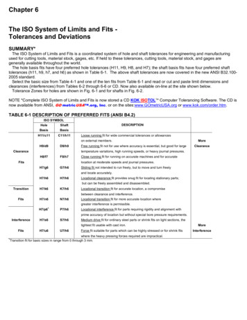
Fits, Tolerance and surface roughnessPreferred Fits:Interference FitsTransition FitsClearance FitsISO SymbolHole Basic Shaft 7/u6U7/h6DescriptionLoose running fit for wide commercial tolerances orallowances on external members.Free running fit not for use where accuracy is essential,but good for large temperature variations, high runningspeeds, or heavy journal pressures.Close running fit for running on accurate machines andfor accurate location at moderate speeds and journalpressures.Sliding fit not intended to run freely, but to move andturn freely and locate accurately.Locational clearance fit provides snug fit for locatingstationary parts; but can be freely assembled anddisassembled.Locational transition fit for accurate location, acompromise between clearance and interference.Locational transition fit for more accurate locationwhere greater interference is permissible.Locational interference fit for parts requiring rigidity andalignment with prime accuracy of location but withoutspecial bore pressure requirements.Medium drive fit for ordinary steel parts or shrink fits onlight sections, the tightest fit usable with cast iron.Force fit suitable for parts which can be highly stressedor for shrink fits where the heavy pressing forcesrequired are impractical.aThe transition and interference shaft basis fits shown do not convert to exactly the same hole basis fit conditions for basicsizes in range from Q through 3 mm. Interference fit P7/h6 converts to a transition fit H7/p6 in the above size range.Fig-10 Methods of specifying tolerances with symbols for mating parts.DesignPage 8
Fits, Tolerance and surface roughnessGeometric Tolerances:aArrowhead(s) may be filled in.(a)(b)Fig-11 (a) Geometric characteristics and (b) modifying symbols, [ANSI Y14.5M-1982].Fig-12 Use of symbols for tolerance of position and form, [ANSI Y14.5M-1982].DesignPage 9
Fits, Tolerance and surface roughnessFig-13 Geometric tolerance.DesignPage 10
Fits, Tolerance and surface roughnessFig-14 Application of symbols to position and form tolerance dimensions [ANSI Y14.5M-1982].Surface Roughness, Waviness, and Lay [ANSI Y14.36-1978]:Symbols(a)Basic Surface Texture Symbol. Surface may be produced by any methodexcept when the bar or circle, (b) or (d), is specified.(b)Material Removal By Machining Is Required. The horizontal bar indicatesthat material removal by machining is required to produce the surface andthat material must be provided for that purpose.Material Removal Allowance. The number indicates the amount of stock tobe removed by machining in millimeters (or inches). Tolerances may beadded to the basic value shown or in a general note.Material Removal Prohibited. The circle in the vee indicates that thesurface must be produced by processes such as casting, forging, hotfinishing, cold finishing, die casting, powder metallurgy or injection moldingwithout subsequent removal of material.Surface Texture Symbol. To be used when any surface characteristics arespecified above the horizontal line or to the right of the symbol. Surfacemay be produced by any method except when the bar or circle, (b) or (d), isspecified.(c)(d)(e)DesignMeaningPage 11
Fits, Tolerance and surface roughness(f)Fig-15 Application of surface texture symbols and surface characteristics [ANSI Y14.36-1978].Fig-16 Lay symbols [ANSI Y14.36-1978].DesignPage 12
Fits, Tolerance and surface roughnessFig-17 Application of surface texture values to symbol [ANSI Y14.36-1978].Preferred Series Roughness Average Values (Ra) [ANSI Y14.36-1978].Micrometers 20.400.500.630.801.00Mictroinches (µin).0.5123456810131620253240Micrometers ictroinches ferred Series Maximum Waviness Height Values [ANSI 0200.00250.0050.0080.012DesignInches 380.50Inches (in).0.0010.0020.0030.0050.0080.0100.0150.020Page 13
Fits, Tolerance and surface roughness0.0200.00080.800.030Fig-18 Surface roughness produced by common production methods [ANSI Y14.5M-1982]. The ranges shownare typical of the processes listed. Higher or lower values may be obtained under special conditions.Classification of Machine Drawings: Assembly Drawings: shows the complete drawing of a given machine, indicating the relativepositions of various components assembled together. Part Drawings or Working Drawings: illustrate the number of views of a single part of amachine required to facilitate it manufacturing. It should furnish all dimensions, limits andspecial finishing processes such as heat treatment, honing, lapping, surface finish.DesignPage 14
Fits, Tolerance and surface roughness Shop Drawings: may be defined as the complete drawing of an object comprising the numberof drawings required to facilitate the fabrication of all parts of the object and their subsequentassembly into a complete product. A shop drawing
Fig-10 Acceptable methods of giving tolerance symbols [ANSI B4.2-1978]. Fits, Tolerance and surface roughness Design Page 8 Preferred Fits: ISO Symbol Description Hole Basic Shaft Basic s H11/c11 C11/h11 Loose running fit for wide commercial tolerances or allowances on external members. H9/d9 D9/h9 Free running fit not for use where accuracy is essential, but good for large temperature .