Transcription
Magnet FAQsSteve Constantinides, Director of TechnologyArnold Magnetic Technologies CorporationFebruary 7, 2013Our World Touches Your World Every Day Arnold Magnetic Technologies1
Questions Permanent magnet key figures of merit Holding force of a magnet Temperature capabilities of magnets When does permeance coefficient matter? Magnetic domains versus particles Raw material prices versus magnet selling price Magnet R&D: are we due for a blockbuster?Other questions? e-mail sconstantinides@arnoldmagnetics.comOur World Touches Your World Every Day Arnold Magnetic Technologies2Each of us has questions about magnetism and magnetic materials. Here are a fewquestions and answers about magnets as used in motors and sensors, magnets for very lowor very high temperatures, differences between a magnetic domain and a magnet particle,raw material cost and why the prices change, will there be enough raw materials, what is thesize of the magnet industry, how to calculate the holding force of a magnet, what ispermeance coefficient and why it matters and more.
What makes a magnet good? Flux density (Br, Residual Induction)Energy Product (BHmax)Resistance to demagnetization (Hcj)Usable temperature rangeChange in magnetization with temperature (RTC)Demagnetization (2nd quadrant) curve shapeRecoil permeability (slightly greater than 1)Corrosion resistance (water, salts, gases)Physical strengthElectrical resistivityMagnetizing field requirementAvailable sizes, shapes, and manufacturabilitySpecific requirements depend upon the applicationOur World Touches Your World Every Day Arnold Magnetic Technologies3 What are a magnet’s key figures of merit? For each application a subset of these characteristics will determine how well the magnetis suited to the application. All of these should be considered by both the magnet manufacturer and the magnet user.
Magnetic Properties & Typical Measurement ToolsHysteresisgraph May also beMagnetic Characteristicestimated by Helmholtz Coil Br, Remanent Induction – indicates available HcJ (or Hci), Intrinsic Coercivity – indicatesflux density of the magnetHysteresisgraph May also beestimated or measured by pulsedemagnetizationthe magnet’s resistance to de-magnetization BHmax, Maximum Energy Product – a figureof merit for how much energy is available formotors and generators Flux, Measure of magnetic output Field Strength, Measure of magneticoutput (flux density) Reversible TemperatureCoefficients, (Br and HcJ) – theseHysteresisgraph May also beestimated from HelmholtzmeasurementsHelmholtz or Search Coil& FluxmeterGaussmeter Hall element or NMR- positional or as part of a fixture (e.g.gap probe)indicate how the magnetic characteristics (Brand HcJ) change with temperature Field Distribution, Measure of thedistribution of the fluxOur World Touches Your World Every Day Hysteresisgraph or VSM or SQUIDmagnetometerGauss probe and x-y-z androtational stage Arnold Magnetic Technologies4 These figures of merit are used to gauge magnetic “quality” and therefore requiremeasurement at one or more points in the supply chain. A device that measures magnetic fields is called a magnetometer. The most common type of magnetometer is the hysteresigraph. Other types of magnetometers are the VSM (vibrating sample magnetometer) and SQUID(semi-conducting quantum interference device). Other magnetic field measuring equipment includes gaussmeters, fluxmeters, fluxgatemagnetometers, NMR (nuclear magnetic resonance) gaussmeters, and combinations ofthese with coils and sensors.
Measurement - HysteresisgraphsMagnetic CoilsSQUIDYoke and Pole CapsComputer ControlAnalog/Digital convertersSearch CoilsPower SupplyFluxmetersA VSM or SQUID can substitute for a hysteresisgraphOur World Touches Your World Every Day Arnold Magnetic Technologies5 The most common equipment for measuring intrinsic magnetic properties is thehysteresigraph (a.k.a. permeameter). The measurement is made in closed magnetic circuit and requires a “regular” geometrywhere the magnet’s poles are flat, parallel and flush with the faces of the pole caps in thehysteresigraph. The use of a Temperature Stage in a hysteresigraph allows properties to be measured atlower and at higher temperatures. Arnold, for example, can measure properties in ahysteresigraph between -40 and 300 ºC. A VSM can use environmental chambers into which the open circuit magnet is insertedfor testing at temperatures ranging from near zero Kelvin to 1000 C.
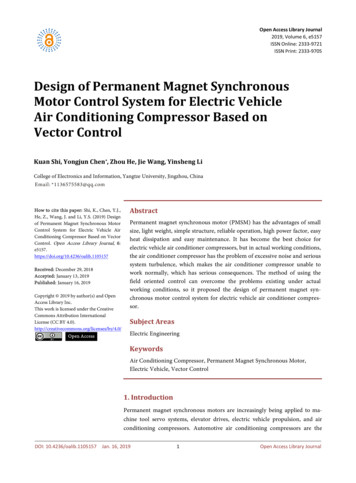
Hysteresisgraph – the PiecesElectromagnet CoilTop Pole PieceAir GapSampleSearch CoilTestTest SampleSearch CoilOur World Touches Your World Every Day Arnold Magnetic Technologies6 The hysteresigraph provides a complete magnetic circuit with pole pieces that adjust toclose the gap with the sample in position. A power supply provides current to energize coils producing a large magnetic field. This10” system can produce 34,000 oersteds in a 0.25” (6.4 mm) gap. The “search coil” is typically constructed with 2, 3 or more coils around the magnetopening. The “B” coil is constructed closest to and in a closed loop around the opening (andmagnet).o It measures the B output (induction) “H” coil is added outside the “B” coil, around the opening, but does not “close the loop”around the magneto It measures only the H output “H” compensating coil is similar to the “H” coil but is electrically connected to the “B”coil in reverseo Subtracts the H field from the “B” coil output providing B-H (intrinsic induction). Electronics process the analog information from the sensors and provide a graphical aswell as digital data output for presentation and analysis.
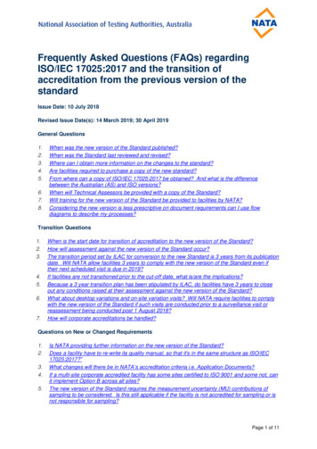
Permanent Magnet Key Characteristics B2nd QuadrantBr0.9 x BrIntrinsic Curveμr, Recoil Permeability,is approximately theslope of the Normalcurve near the B axisEnergy product isrelated to BrBHmax Br2 / (4 μr)μr 1.05BdNormalCurveWhen Normal curve fromBr to Operating Point isNear-linear such as forferrite, SmCo and sinteredNeo magnetsBHmax-HHciAlso called HcJOur World Touches Your World Every Day Hc HkHcBHd Arnold Magnetic Technologies7 For permanent magnets we deal most often with just the second quadrant. Most of the key figures of merit for permanent magnet materials are indicated on thechart. The maximum energy product can be estimated as shown here from just the Br. Conversely, the Br can be estimated when the maximum energy product is known. As shown, this material would be considered a straight line (Normal curve) or square loop(Intrinsic curve) material since the Normal curve is straight to the maximum energy point.
Questions Permanent magnet key figures of merit Holding force of a magnet Temperature capabilities of magnets When does permeance coefficient matter? Magnetic domains versus particles Raw material prices versus magnet selling price Magnet R&D: are we due for a blockbuster?Other questions? e-mail sconstantinides@arnoldmagnetics.comOur World Touches Your World Every Day Arnold Magnetic Technologies8
Holding ForceAffected by: Quality of the magnet-steel interface– Flatness and uniformity of the surfaces– Roughness of the surfaces– Surface coating or gap-creators Rigidity during pull-off– Pull-away at 90 to the plane of the interface– Both materials remain rigid under stress to prevent “peel away” Localized saturation of the steel Non-uniformity of the magnet or assembly creates nonuniform flux and holding force distributionMost calculations overstate the actual holding forceOur World Touches Your World Every Day Arnold Magnetic Technologies9 The closer to the substrate (steel) the greater the holding force of a magnet or magnetassembly. As the magnet moves away from the steel, the pull is reduced. If the steel is painted or coated or covered with a non-magnetic material, this forms a gapwhich reduces the holding force. A rough surface also reduces the holding force. A refrigerator magnet is usually flexible and easy to remove from the refrigerator bypeeling it away from the steel by lifting a corner or edge to break the magnetic attraction.Similarly, if a rigid magnet is attached to flexible steel, the steel can more easily peelaway from the magnet. It is tempting to increase holding force by increasing the strength of the magnet. Butwhen a strong magnet is attached to a thin sheet of steel, it is likely to result in the steelbecoming “saturated”. Once the steel is saturated very little additional holding force canbe expected. If the magnet or steel is irregular – has stronger and weaker areas, the weaker region canpull away first thus causing lower holding strength than might be expected. Because of these and other variations, Arnold has avoided offering a simple formula forcalculating holding force and encourages FEA followed by thorough testing of the design.
Holding (Breakaway) ForceF FABC4A B22 C4SINewtonsm2Tesla1CGSDynescm2Gauss4 B.D. Cullity and C.D. Graham, Introduction to Magnetic Materials, 2nd ed., IEEE Press, 2009, p.501-2FkBAF k A B2EnglishPounds (force)0.577kGin2B is induction at the contact point of the magnet assembly and the substratek is a shape and contact coefficientRollin J. Parker, Advances in Permanent Magnetism, John Wiley & Sons, Inc., 1990, p.186-9Our World Touches Your World Every Day Arnold Magnetic Technologies10 But in the event you wish to know. These are two versions of the same formula for holding force, one in cgs & SI and one inEnglish units. “B” is the induction, in gauss (or Tesla), at the contact point between the magnet ormagnetic assembly and the substrate (steel). “A” is the cross-sectional area of contact between magnet (or magnetic assembly) and thesteel. C4 and k are constants.
Holding Force for Magnets & AssembliesRollin J. Parker, Advances in Permanent Magnetism, John Wiley & Sons, Inc., 1990, p.186-9Our World Touches Your World Every Day Arnold Magnetic Technologies11 Because of the complications associated with holding force and because pull at a distanceis so often useful, it is more common to find charts showing attractive force as a functionof gap between magnet and steel for a limited number of magnet configurations. In a design application, the engineering group might be well-advised to generate such achart for the application and then design a margin of safety by testing imperfectassemblages.
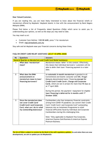
Holding Magnets: PrincipleSteel fluxconcentratorsNNS Flux from the disk-shaped ferrite magnet ischanneled from the pole at the top to themetal plate and then to the magnetic pole atthe bottom of this illustration. Holding force derives from the fact that thefield is “conducted” more easily in the steelthan in the air.Our World Touches Your World Every Day SSteel striker plate Arnold Magnetic Technologies12 These illustrations exemplify two types of holding/latching devices. The top left illustration is of a cross-section of a “pot magnet.” Magnets of modest strength can hold with great force when the field is concentrated inthis manner. The holding force diminishes rapidly as the steel plate is separated from the magnetassembly and holding force is greatly affected by the flatness of the steel plate – the fitbetween pot magnet and substrate. If the steel plate is too thin to carry all the flux, the holding force will also be diminished. These assemblies often include a hole in the center of the top for fastening attachmentsand they use a doughnut-shaped magnet. Applications include roof-mount antennas for cars. Devices based on rectangular shaped magnets are common for use in cabinet latches. The magnet is protected from chipping by being recessed from the contact. The steel flux concentrators are loosely held allowing them to adjust for good contact withthe striker plate.
Holding Magnets: Flat and/or FlexibleOptional steel sheetNSNSNSNSNSNSNSNSNSSteel substrate The creation of multiple adjacent strips ofalternate magnet orientation formsextended regions of opportunity for flux totravel through steel rather than air. Holding force is a function of Poles perInch and distance from the steel plate. This is the principle behind Flexmag’s AdSpecialty flexible magnets and Plastiform’scommercial products.Our World Touches Your World Every Day Arnold Magnetic Technologies13 Flexible ferrite magnets are commonly used in advertising such as in “refrigeratormagnets” and are produced in various thickness and pole spacing (see next slides).
“Throw” of a MagnetNSNSNSNSNSNSNSNSNSNSNSSNSNThe “throw” of the magnetic field is thedistance from the magnet exhibitinghigh magnetic field strengthPoles that are spaced more widely havegreater throw and will attract morestrongly from a distance.But closer pole spacing provides greater holding force when incontact with a steel plate.Our World Touches Your World Every Day Arnold Magnetic Technologies14 In these illustrations, the flexible magnet has a steel backing to assist the magnetic returnpath and raise the holding strength of the magnet. As one moves away from the surface of a magnet assemblage, the strength of themagnetic field diminishes. When the poles are spaced close together the field drops off quickly (top illustration).Conversely, when they are spaced further apart, the field is stronger at large distancesfrom the magnet surface (bottom illustration). The top magnet here has superior holding force when directly in contact with steel. Thebottom magnet has greater holding power as the gap between magnet and steel increases. The overall holding strength is a function of many things among which is the total lengthof the lines representing the joint (neutral zone) between north and south poles. Each ofthese joints contributes to the holding force.
Holding Force of Flexible MagnetsUsing magnet viewing paper, we can seethe magnetic pole structure.The light colored lines represent the neutralzone between north and south poles.www.magne-rite.comOur Wo
These figures of merit are used to gauge magnetic “quality” and therefore require measurement at one or more points in the supply chain. A device that measures magnetic fields is called a magnetometer. The most common type of magnetometer is the hysteresigraph. Other types of magnetometers are the VSM (vibrating sample magnetometer) and SQUID (semi-conducting quantum .