Transcription
Open Access Library Journal2019, Volume 6, e5157ISSN Online: 2333-9721ISSN Print: 2333-9705Design of Permanent Magnet SynchronousMotor Control System for Electric VehicleAir Conditioning Compressor Based onVector ControlKuan Shi, Yongjun Chen*, Zhou He, Jie Wang, Yinsheng LiCollege of Electronics and Information, Yangtze University, Jingzhou, ChinaHow to cite this paper: Shi, K., Chen, Y.J.,He, Z., Wang, J. and Li, Y.S. (2019) Designof Permanent Magnet Synchronous MotorControl System for Electric Vehicle AirConditioning Compressor Based on VectorControl. Open Access Library Journal, ved: December 29, 2018Accepted: January 13, 2019Published: January 16, 2019Copyright 2019 by author(s) and OpenAccess Library Inc.This work is licensed under the CreativeCommons Attribution InternationalLicense (CC BY en AccessAbstractPermanent magnet synchronous motor (PMSM) has the advantages of smallsize, light weight, simple structure, reliable operation, high power factor, easyheat dissipation and easy maintenance. It has become the best choice forelectric vehicle air conditioner compressors, but in actual working conditions,the air conditioner compressor has the problem of excessive noise and serioussystem turbulence, which makes the air conditioner compressor unable towork normally, which has serious consequences. The method of using thefield oriented control can overcome the problems existing under actualworking conditions, so it proposed the design of permanent magnet synchronous motor control system for electric vehicle air conditioner compressor.Subject AreasElectric EngineeringKeywordsAir Conditioning Compressor, Permanent Magnet Synchronous Motor,Electric Vehicle, Vector Control1. IntroductionPermanent magnet synchronous motors are increasingly being applied to machine tool servo systems, elevator drives, electric vehicle propulsion, and airconditioning compressors. Automotive air conditioning compressors are theDOI: 10.4236/oalib.1105157Jan. 16, 20191Open Access Library Journal
K. Shi et al.core part of electric vehicle air conditioners, solving the problem of excessivenoise and serious system oscillation [1].Permanent magnet synchronous motor (PMSM) has the characteristics ofsmall size, simple structure, high power factor, reliable operation, easy heat dissipation and easy maintenance. It has been widely used in machine tool servosystem, elevator drive, electric vehicle propulsion, air conditioner compressor,etc. [2]. Compared with ordinary air conditioner compressors, PMSM has significant advantages in the application of electric vehicle air conditioner compressors.PMSM has the characteristics of wide speed regulation range, high control precision and small torque ripple [3]. With the development of high-speed microprocessors, advances in power electronics, and continuous improvement of controlalgorithms, the application of PMSM technology has become more mature andextensive. Based on the actual working conditions of electric vehicle air conditioner compressor, based on the analysis of PMSM vector control working principle, the design of permanent magnet synchronous motor control system forelectric vehicle air conditioner compressor is completed. With dsPIC30F4011 asthe core, electric vehicle air conditioner compressor is constructed, PMSM control system.In the traditional automotive system, the compressor and the car-driven engine need to be used together, and the car must be started before the carair-conditioning compressor can work normally. In the electric vehicle system,the whole system is electric, and the compression system does not need to relyon the driving of the automobile wheel engine. Up to now, the air conditioningsystem has become an independent part, as a separate unit, with independentpower supply system and vehicle main system. The signal transmission throughcommunication enables individual control and variable frequency control functions. The efficiency ratios of the compressor’s traditional mechanical mode andelectric mode are shown in Table 1.2. The principle of PMSM Work2.1. The Mathematical Model of PMSMTo simplify the analysis, assume that the magnetic path of the PMSM is not saturated and the spatial magnetic field is sinusoidal, ignoring hysteresis and eddycurrent losses [4].The direction of the PMSM rotor permanent magnet magnetic field is definedas the d-axis, and the d-axis is orthogonal to the q-axis. The dq coordinateTable 1. Comparison of the efficiency of the traditional mechanical mode and electricmode of the compressor.DOI: 10.4236/oalib.1105157Model rsComprehensiveMotor drive0.90.650.750.44Mechanical drive0.40.950.750.292Open Access Library Journal
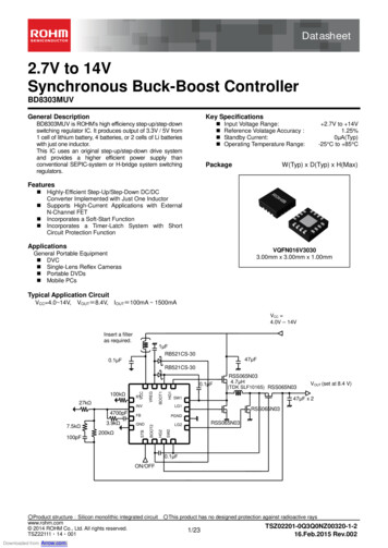
K. Shi et al.system is fixed on the rotor, rotates synchronously with the rotor, and the anglebetween the d-axis and the A-axis is a variable, physical model [5].The mathematical model of the PMSM in the synchronously rotated d-qcoordinate system is established as follows.Motor flux linkage equation: Ld id ψ f ψd ψ q Lq iq(1)Torque equation: Te3Pn (ψ d iq ψ q id )2(2)Stator voltage equation:dψ d ud Rs id dt ωeψ q u R i dψ q ω ψs qe d qdt(3)Equation of motion:Te TJ Ldωm Bωmdt(4)Ld , Lq —d, q-axis equivalent inductance;ψ f —Permanent magnet flux linkage;Rs —Stator resistance;ωe , ωm —Electrical angular velocity and mechanical angular velocity;Te —Electromagnetic torque;pn —Magnetic pole pair;TL —Load torque;J—Moment of inertia;B—Coefficient of friction.According to formula (3), it can be concluded:333pnψ d iq pn ( Ld id ψ f ) iq pnψ f iq222T e(5)as follows:Te 3pnψ f iq2(6)It can be known from the above equation that the electromagnetic torque ofthe motor is determined only by the q-axis current, which realizes the decoupling of the electromagnetic torque of the motor. Therefore, it can be seen that after the control strategy of id 0 , the permanent magnet synchronous motor isequivalent to a single-excitation DC motor, and only the torque current iq canbe controlled to control the electromagnetic torque, thereby realizing the speedcontrol. The schematic diagram of PMSM vector control is shown in Figure 1.DOI: 10.4236/oalib.11051573Open Access Library Journal
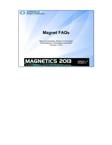
K. Shi et al.Figure 1. PMSM vector control schematic.2.2. Principle of PMSM ControlSVPWM refers to outputting different pulse sequences according to differentcombinations of three switching tubes of the upper arm of the three-phase inverter bridge for controlling the inverter output three-phase sinusoidal voltageor three-phase sinusoidal current [6].The six switching devices are controlled by six control signals. Each group ofupper and lower bridge switching devices can only be turned on and the other isturned off. Therefore, the inverter has eight working states, corresponding toeight voltage vectors. Set the upper bridge to conduct, the lower bridge ismarked as 1, the lower bridge is turned on, and the upper bridge is closed as 0.The formula for the phase voltage can be derived: ua 2 1 1 a u 1 U 1 2 1 b b 3 dc uc 1 1 2 c (7)ua , ub , uc —Three-phase stator phase voltage in A-B-C coordinate system.Using the Clark transform, uα , uβ in the α-β coordinate system can be obtained.1 1 uα 22 u 33 β 0 21 ua 2 ub3 uc 2 (8)The eight voltage vector distributions are shown in Figure 2.From the above figure, there are 6 non-zero vector amplitudes in the 8 basicspace voltage vectors, the phase difference is 60 , the vector space is divided into6 sectors, and the other 2 are zero vectors. According to the parallelogram rule,DOI: 10.4236/oalib.11051574Open Access Library Journal
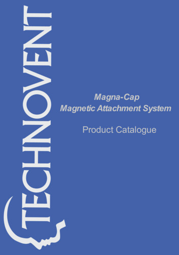
K. Shi et al.Figure 2. Basic space vector.these 8 basic space vectors can be used to synthesize any voltage vector that doesnot exceed the maximum amplitude [7]. SVPWM technology uses these 8 basicspace vectors to approximate a given reference voltage vector U ref .3. Design of PMSM Control System3.1. Hardware Design of PMSM Control SystemThe hardware structure of the permanent magnet synchronous motor controlsystem for electric vehicle air conditioner compressor is shown in Figure 3. Itcan be seen from Figure 3 that the hardware structure of the control systemconsists of three parts: control module, communication module and powermodule.Among them, the control chip is dsPIC30F4011, which is a high-performance16-bit digital signal controller with low-power high-speed flash technology, wideoperating voltage range and efficient and fast working speed. It can be reprogrammed under software control, power management mode to meet system requirements.The power module input terminal is connected to 230 V high-voltage DC powerto supply power to the power module and the control module. The step-down isachieved by using a high frequency transformer. The DC-DC Converter UC2843is used to control the switching of the MOS tube, and the direct current is converted into a high-frequency oscillation pulse waveform, and a low-voltage alternating current is generated by the transformer. After low-voltage AC rectification, the output voltage of the control chip is output via the three-terminalregulator LM117.Communication circuit uses optocoupler isolation, which can be abnormal inthe input signal. The protection chip is not burned out intelligent power module.Barrier protection function, when there are temperature, current, voltage andother faults, the FO pin of the module will output a fault signal to stop the motor, thereby playing a protective role.3.2. Software Design of PMSM Control SystemIn addition to the hardware system, the control system requires software toDOI: 10.4236/oalib.11051575Open Access Library Journal
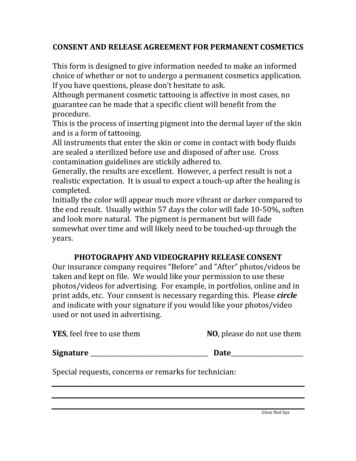
K. Shi et al.Figure 3. Control system hardware structure.Figure 4. Block diagram.implement the functions of the system. The main function of this software is torealize the FOC and subroutine modules of permanent magnet synchronousmotor, making full use of dsPIC30F4011 chip computing function and softwarefiltering. The whole program is developed in the chip-specific development environment MPLAB with C language. The software system has good real-timeand reliability, which is convenient for modification and debugging.The control program consists of a main program and an interrupt servicesubroutine. The specific process block diagram is shown in Figure 4.4. Experimental Results and AnalysisThe structure of the body, rotor and stator of the motor used in the drive systemDOI: 10.4236/oalib.11051576Open Access Library Journal
K. Shi et al.are shown in Figure 5 and Figure 6.The technical specifications of the motor used in this control system areshown in Table 2.Figures 7-9 are waveform diagrams of the respective phase currents measuredat n 1570 r min , n 2370 r min , and n 3350 r min .5. ConclusionThe permanent magnet synchronous motor control system of electric vehicle airFigure 5. Structure diagram of motor body.Figure 6. Structure diagram of rotor and stator.Figure 7. n 1570 r min , Phase current waveform.DOI: 10.4236/oalib.11051577Open Access Library Journal
K. Shi et al.Figure 8. n 2370 r min , Phase current waveform.Figure 9. n 3350 r min , Phase current waveform.Table 2. Motor technical indicators.Rated speed3000 r/minStator resistance0.0187 ΩRated power4430 wStraight axis self-inductance0.02547 HRated Voltage230 VCross-axis self-inductance0.02816 HRated torque3 N·mPermanent magnet flux linkage0.1717 WbMagnetic polelogarithm4Moment of inertia2.26 10 5 kg·m2conditioner compressor designed in this paper has been tested several times toanalyze the control performance of the motor. The results show that the controlsystem can significantly improve the normal operation of the drive motor in theenvironment of excessive noise and severe system oscillation, and the workingability to meet the actual working conditions of electric vehicle air conditioningcompressors.Conflicts of InterestThe authors declare no conflicts of interest regarding the publication of this paper.DOI: 10.4236/oalib.11051578Open Access Library Journal
K. Shi et al.ReferencesDOI: 10.4236/oalib.1105157[1]Yamada, E. and Zhao, Z.M. (2000) Applications of Electrical Machine for VehicleDriving System. Proceedings IPEMC 2000: Third International Power Electronicsand Motion Control Conference, 3, 1[2]Zheng, J.G., Wu, H.X., Zheng, P., Pi, L.P. and Huang, Y.P. (2017) Modeling andSimulation of Speed Loop Control Technology for Permanent Magnet SynchronousMotor Servo System. 2017 IEEE Transportation Electrification Conference and Expo, Asia-Pacific (ITEC Asia-Pacific), Harbin, 2-5 August 2017, ]Liu, H., Gao, Z., Wu, W., Chow, L. and Wu, T. (2015) Design of a High-EfficiencyPermanent Magnet Synchronous Motor and Inverter System. IECON 2015—41stAnnual Conference of the IEEE Industrial Electronics Society, Yokohama, 9-12November 2015, 004996-005001.[4]Suthamno, K. and Sujitjorn, S. (2012) Modelling of Permanent Magnet Synchronous Motor Incorporating Core-Loss. Open Access Library Journal, 4, 2846-2853.[5]Zhai, L. and Li, H. (2008) Modeling and Simulating of SVPWM Control System ofInduction Motor in Electric Vehicle. 2008 IEEE International Conference on Automation and Logistics, Qingdao, 1-3 September 2008, 5[6]Ping, L. and Lan, C. (2012) Study on Controlling and Simulation of Drive Systemfor Permanent Magnet Synchronous Motor in Electrical Vehicle. 2012 Power Engineering and Automation Conference, Wuhan, 18-20 September 2012, , L., Wang, C., Shi, H., Xin, R. and Wang, L. (2017) Simulation of PMSMField-Oriented Control Based on SVPWM. 2017 29th Chinese Control and DecisionConference (CCDC), Chongqing, 28-30 May 2017, 49Open Access Library Journal
system, elevator drive, electric vehicle propulsion, air conditioner compressor, etc. [2]. Compared with ordinary air conditioner compressors, PMSM has signif-icant advantages in the application of electric vehicle air conditione