Transcription
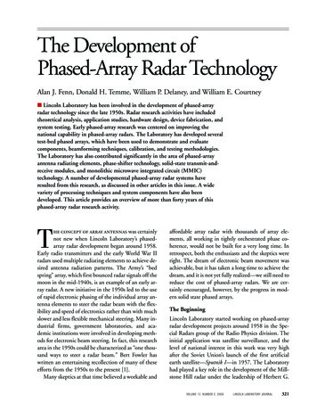
FENN, TEMME, DELANEY, AND COURTNEYThe Development of Phased-Array Radar TechnologyThe Development ofPhased-Array Radar TechnologyAlan J. Fenn, Donald H. Temme, William P. Delaney, and William E. Courtney Lincoln Laboratory has been involved in the development of phased-arrayradar technology since the late 1950s. Radar research activities have includedtheoretical analysis, application studies, hardware design, device fabrication, andsystem testing. Early phased-array research was centered on improving thenational capability in phased-array radars. The Laboratory has developed severaltest-bed phased arrays, which have been used to demonstrate and evaluatecomponents, beamforming techniques, calibration, and testing methodologies.The Laboratory has also contributed significantly in the area of phased-arrayantenna radiating elements, phase-shifter technology, solid-state transmit-andreceive modules, and monolithic microwave integrated circuit (MMIC)technology. A number of developmental phased-array radar systems haveresulted from this research, as discussed in other articles in this issue. A widevariety of processing techniques and system components have also beendeveloped. This article provides an overview of more than forty years of thisphased-array radar research activity. was certainlynot new when Lincoln Laboratory’s phasedarray radar development began around 1958.Early radio transmitters and the early World War IIradars used multiple radiating elements to achieve desired antenna radiation patterns. The Army’s “bedspring” array, which first bounced radar signals off themoon in the mid-1940s, is an example of an early array radar. A new initiative in the 1950s led to the useof rapid electronic phasing of the individual array antenna elements to steer the radar beam with the flexibility and speed of electronics rather than with muchslower and less flexible mechanical steering. Many industrial firms, government laboratories, and academic institutions were involved in developing methods for electronic beam steering. In fact, this researcharea in the 1950s could be characterized as “one thousand ways to steer a radar beam.” Bert Fowler haswritten an entertaining recollection of many of theseefforts from the 1950s to the present [1].Many skeptics at that time believed a workable andTaffordable array radar with thousands of array elements, all working in tightly orchestrated phase coherence, would not be built for a very long time. Inretrospect, both the enthusiasts and the skeptics wereright. The dream of electronic beam movement wasachievable, but it has taken a long time to achieve thedream, and it is not yet fully realized—we still need toreduce the cost of phased-array radars. We are certainly encouraged, however, by the progress in modern solid state phased arrays.The BeginningLincoln Laboratory started working on phased-arrayradar development projects around 1958 in the Special Radars group of the Radio Physics division. Theinitial application was satellite surveillance, and thelevel of national interest in this work was very highafter the Soviet Union’s launch of the first artificialearth satellite—Sputnik I—in 1957. The Laboratoryhad played a key role in the development of the Millstone Hill radar under the leadership of Herbert G.VOLUME 12, NUMBER 2, 2000LINCOLN LABORATORY JOURNAL321
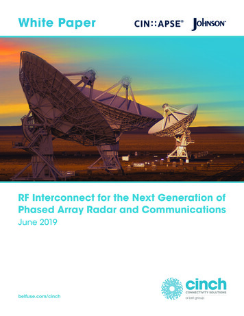
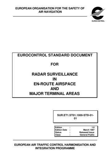
FENN, TEMME, DELANEY, AND COURTNEYThe Development of Phased-Array Radar TechnologyWeiss, a radar visionary. At that time, the MillstoneHill radar was one of the few radar instruments in theworld with satellite detection and tracking capability.Weiss, along with others in the U.S. Air Force, foresaw that the United States would soon need the capability to detect all satellites passing over its territory.The volume of radar surveillance needed to accomplish this task was clearly enormous, which meantthat radars of great power, antenna aperture, andbeam agility would be required.One approach to solving this surveillance problemwas to build a large planar array of some five thousand UHF elements. Weiss’s intuition told him thenation was not yet equipped with the capability toproduce reliable low-cost components that would allow engineers to implement a radar with five thousand individual transmitters and receivers. The country, however, did have some big UHF klystrons in theMillstone Hill radar transmitter (2.5-MW peakpower, 100-kW average power), and klystrons such asthese could be incorporated into a phased-array radarof sorts. Thus began a search of a variety of hybridmechanically scanned and electronically scanned antenna-array configurations that would use a few ofthese big klystrons.Figure 1 is a drawing of the favored hybrid concept, which featured a cylindrical receiver reflector140 ft high by 620 ft long [2]. Three rotating verticallinear arrays formed multiple receive beams in eleva-tion angle, which were mechanically scanned acrossthe cylindrical reflector. The klystron transmitterswere coupled to three horizontal linear arrays that didnot use the reflector, nor did they electronically scan.They formed a fan beam in elevation angle, whichwas scanned across a large portion of the sky as a result of the mechanical drive in a large center hub(hence this massive machine was given the irreverentnickname “centrakluge”). Average power output froma group of 900-MHz klystrons was to be one megawatt. This hybrid array concept had great power,great receiving aperture, and a rapid wide-angle scancapability. It was configured to survey huge volumesof space, so that one installation could detect all satellites passing over the United States up to an orbital altitude of three thousand nautical miles.The Laboratory’s focus at the start of this development effort was to find efficient ways to build thelong linear phased arrays for the receivers. A variety ofbeamforming schemes were investigated, includingbeamformers at intermediate frequencies (where highlosses could be tolerated), radio-frequency (RF) diode-switched phase shifters (where losses needed tobe kept very low), and RF multibeam beamformers.This hybrid electronic-scan/mechanical-scan approach had critics who argued that it could track satellites only in a track-while-scan mode, and it couldnot track high-interest satellites outside of its somewhat restricted vertical search window. The nationFIGURE 1. Drawing of a proposed 1950s-era hybrid phased-array radar that combined mechani-cally scanned and electronically scanned antenna-array configurations.322LINCOLN LABORATORY JOURNALVOLUME 12, NUMBER 2, 2000
FENN, TEMME, DELANEY, AND COURTNEYThe Development of Phased-Array Radar Technologyseemed to favor the five-thousand-element, fullphased-array approach, an option that was encouraged by a significant U.S. Air Force effort on electronic scanning array radar (ESAR) at the BendixCorporation. Also, many engineers in the defensecommunity of that era really wanted the nation tobuild a full planar phased-array radar.The increase in national interest in ballistic missiledefense shifted everyone’s focus toward planar phasedarrays because the challenges and intricacies of activemissile defense would demand every ounce of radarbeam agility, flexibility, power aperture, and wideangle scan that the radar community could muster.Therefore, interest in linear arrays faded—planar arrays were what was needed—but the nation was still along way from achieving the dream of an affordableplanar phased array.The Early YearsBy 1959, a cadre within the Special Radars group atthe Laboratory had formed around a phased-array visionary, John L. Allen, to push the development ofphased arrays for a wide variety of military missions,with ballistic missile defense as the mission for whichsuch radars were most obviously needed. Allen’s goalwas to conduct a broad development effort on arrays,starting from array theory and extending to practicalhardware developments, in order to improve the national capability in phased arrays to a point where wehad reliable and reasonable-cost array components, avariety of beam-scanning techniques, and a soundunderstanding of array theory. The work had to havea practical orientation, and the Laboratory’s efforthad to connect with and influence the wide diversityof array research going on in industry and government laboratories.Thus in 1959 the Laboratory launched a broad attack on new developments in theory and hardware,and through the ensuing five years the phased-arrayeffort functioned very much as an intellectual openhouse to share insights with other researchers and as aclearinghouse to help industry try out its ideas. TheLaboratory developments were chronicled in a seriesof yearly reports entitled “Phased-Array Radar Studies,” which were best-sellers in the array community[3–6].The Sixteen-Element Test ArrayThe strong emphasis on making phased arrays intopractical devices led to the construction of a 900MHz, sixteen-element linear-array fixture as an arraytest bed, where array components, such as antenna elements, low-noise amplifiers, intermediate-frequency(IF) amplifiers, mixers, transmitters, and beamforming techniques could be tried, tested, and exercised.The array test bed was mounted as a feed looking intoa parabolic cylinder reflector, and this whole antennastructure was mounted on a rotating pedestal andhoused in a radome on the rooftop of LincolnLaboratory’s C Building, as shown in Figure 2. A widevariety of embryonic phased-array receiver and transmitter components were developed and tested in thissixteen-element array over the first five years of theLaboratory’s program.FIGURE 2. Sixteen-element linear-array test-bed facility atLincoln Laboratory in 1960. Phased-array components suchas antenna elements, low-noise amplifiers, intermediate-frequency amplifiers, mixers, transmitters, and beamformingtechniques were tested in this facility.VOLUME 12, NUMBER 2, 2000LINCOLN LABORATORY JOURNAL323
FENN, TEMME, DELANEY, AND COURTNEYThe Development of Phased-Array Radar TechnologyPhased-Array ComponentsThe initial experimentation with array antenna elements started with log-periodic structures that werereported to have a desirable low mutual coupling.The early experiments, however, showed that dipoleelements were better candidates for arrays, and muchof the ensuing work was on dipole radiators.Low-noise front-end amplifiers for phased-arrayreceivers were a substantial area of investigation.Work started with a complex electronic device calledthe electron-beam parametric amplifier, invented byRobert Adler at Zenith Radio Corporation and GlenWade at Stanford University. More conventional diode-based parametric amplifiers were also investigated. The desire for simpler and lower-cost approaches led to work on tunnel-diode amplifiers; thiseffort finally settled on low-noise transistor amplifierswith the advent of the field-effect transistor.IF amplifiers, mixers, and transmitters using medium-power tetrodes were also developed and testedin configurations that would allow them to fit in aplanar-array structure at 900 MHz.One of the major efforts was in the development ofvarious ways to steer the radar beam electronically.Beamformers that worked at IF were one of the earliest approaches, and a variety of schemes were builtand tested. Techniques that worked directly at RFwere also investigated. One invention of that timewas the Butler beamforming matrix, which receivedearly and comprehensive testing at Lincoln Laboratory after its invention by Jesse Butler of Sanders Associates around 1960 [7, 8]. An interesting nuance ofthe Butler matrix was its microwave wiring diagram,which was identical to the computational flow graphof the fast Fourier transform that hit the headlines anumber of years later. In retrospect, this similaritywas no surprise, because the Butler matrix was indeeda Fourier transformer [9, 10]. In fact, the Laboratorybuilt a low-frequency version of the Butler matrix toserve as a Fourier transformer for a radar burst-waveform-matched filter.The search for digital devices that could electronically scan radar beams led to a major research effort indigital diode-switched microwave phase shifters. TheLaboratory’s work in this area contributed substan324LINCOLN LABORATORY JOURNALVOLUME 12, NUMBER 2, 2000tially to the development of workable diode phaseshifters that found their way into a wide variety ofphased-array radars. This diode phase-shifter workand related ferrite phase-shifter work are described ina subsequent section of this article.Retrospective on the Early YearsThere were several enduring values to the phased-array work in these early years. First, the Laboratoryquickly became “wet all over” in this new technologyof phased arrays. The work covered a broad front, including theory, hardware, experimental arrays, andsystems analysis on military problems requiringphased arrays. Second, the focus on driving for thepractical, low-cost, highly reliable components thatwould make phased arrays a viable future optionhelped set the appropriate tone for the national research agenda in phased arrays of that era.* Third, theLincoln Laboratory group under the leadership ofJohn Allen was very much an open house and a forumfor industry, academic, and government workers ofthat day. In this fashion, the work performed at theLaboratory had an amplified impact that went wellbeyond the efforts of the ten or so researchers in theLaboratory phased-array radar group.The Ensuing YearsIn subsequent years, Lincoln Laboratory made significant contributions to phased-array technology, including array-element design, phase shifters, solidstate transmit-and-receive modules, gallium-arsenidemonolithic microwave integrated circuits, and arraycalibration and testing.* In 1970 Lincoln Laboratory cosponsored a phased-arraysymposium [11] in New York City, which brought togethermany contributors to the field of phased-array technology.The symposium covered all the major aspects of phased-array theory, design, and manufacturing, including array-element design, feed networks and beam-steering methods,phase-shifter technology, solid state technology, and arraytesting techniques. Carl Blake and Bliss L. Diamond of theLaboratory were prominent in the organization of this significant phased-array meeting, which assessed the state of theart and provided a comprehensive, up-to-date source of information on phased-array antennas.
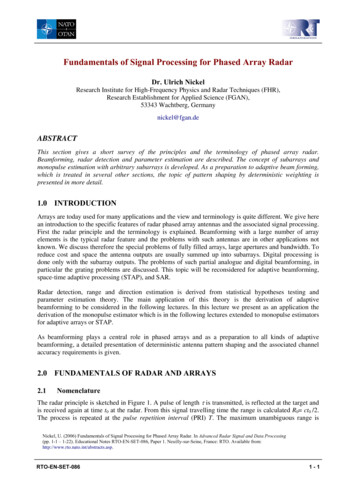
FENN, TEMME, DELANEY, AND COURTNEYThe Development of Phased-Array Radar TechnologyθArray-Element DesignOne of the fundamental difficulties in designing aphased array is that significant portions of the microwave power transmitted by one element of the arraycan be received by the surrounding array antenna elements. This effect, which is known as array mutualcoupling, can result in a substantial or total loss oftransmitted or received radar signal, depending onthe coherent combination of all of the mutual-coupling signals in the array. The amplitudes and phasesof the array mutual-coupling signals depend primarily on the shape of the radiating antenna elements,the spacing between the array elements, and the number of radiating elements. There are as many differentdesign possibilities for phased arrays as there are dozens of different radiating array elements to choosefrom, and the spacing and number of radiating elements can vary widely, depending on the scanning requirements. Naturally, we needed to understand fullythe mutual-coupling aspects of whatever radiated element was selected. Thus the Laboratory investigatedmany different array-element designs, taking into account mutual-coupling effects.The Laboratory’s investigation of the theory of array antennas began in 1958 and has continuedthrough the ensuing years. Allen’s early work contributed markedly to the understanding of array antennasin that era [12]. There was a strong focus on understanding and modeling array mutual coupling and itsimpact on array performance. As described below,this theoretical and experimental work was continuedat the Laboratory by Diamond [13], Diamond andGeorge H. Knittel [14], Gerasimos N. Tsandoulas[15–19], and Alan J. Fenn [20, 21].A significant challenge in designing phased arraysis meeting requirements of scan volume and bandwidth while avoiding blind spots and maintaininglow sidelobes [11, 22–26]. Figure 3(a) shows the concept of a corporate-fed phased-array antenna that usesphase shifters to electronically steer the radar beamover the scan sector. The RF source produces a radarwaveform that is divided up into individual pathscalled element channels, each containing a phaseshifter and amplifier.Figure 3(b) shows an idealized element-radiationMutual coupling. . . Antennaelements.AmplifiersφφφφφφφPhase shiftersPower dividerRF source(a)Scan sectorAngle(b)(c)FIGURE 3. General concept of a phased-array antenna thatelectronically combines element patterns to point the radarbeam in a particular direction. (a) The antenna uses phaseshifters to steer the radar beam electronically over the scansector. The radio-frequency (RF) source produces a radarwaveform that is divided up into individual paths called element channels, each containing a phase shifter and amplifier. (b) An idealized radiation pattern from a single antennaelement covers the scan sector, with signal strength dropping outside of the sector. (c) When all the phase shifters ofthe array are properly aligned, the array produces a mainbeam in the desired pointing direction.VOLUME 12, NUMBER 2, 2000LINCOLN LABORATORY JOURNAL325
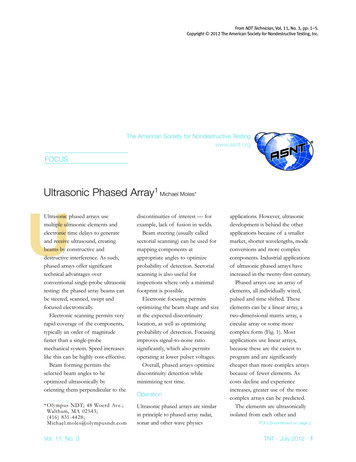
FENN, TEMME, DELANEY, AND COURTNEYThe Development of Phased-Array Radar Technology326LINCOLN LABORATORY JOURNALVOLUME 12, NUMBER 2, 20000Relative gain (dB)(a)Ideal–10Blind spots–20Blind spots must beavoided over thedesired scan sector–30Scan sector–401(b)Scan sectorReflection coefficientpattern that covers the scan sector, with signalstrength dropping outside of the sector. When all thephase shifters of the array are properly aligned, the array produces a main beam in the desired pointing direction, as shown in Figure 3(c). Generally, the corporate feed is designed with minimal crosstalk betweenchannels. Once the signals have reached the radiatingantenna elements, however, a significant amount ofcrosstalk (i.e., array mutual coupling) occurs. Theamplitudes and phases of these mutual-coupling signals can seriously impact the performance of thephased array.If the array-element spacing is around one-halfwavelength, substantial amounts of mutual couplingcan occur. This coupling manifests itself in often deleterious changes in the element’s radiation patternand its reflection coefficient. Unless care is taken inthe design of the array, blind spots in the radar-scansector can occur. These blind spots are angles wherethe element pattern has a null and the reflection coefficient of the array has a peak close to unity, as depicted in Figure 4. At these blind spots the total radarsignal is significantly reduced in amplitude.Sometimes we would like to place a blind spot indirections where it is undesirable to transmit or receive radar energy. For example, Figure 5 compares abroadside-peak radiator (dipole or waveguide aperture) and a broadside-null radiator (monopole antenna). The latter element is useful when broadsideradiation is undesirable, such as in reducing broadsideclutter and jamming. As the radar beam is steeredaway from 0 (broadside) toward 60 , the conventional broadside-peak-type element radiation patterndrops off, but the broadside-null-type element radiation pattern increases to a peak at about 45 to 50 .Early developments of phased-array radiating element technology were conducted at Lincoln Laboratory during the period from 1959 to 1967. Beginningin 1959, the Laboratory contributed to the theoretical understanding of phased arrays, particularly theeffects of array mutual coupling on the performanceof various configurations of dipole arrays; for example, the reports by Allen et al. [3–6, 27–32]. Figure6 shows one of the early L-band dipole-phased-arraytest beds used in measuring array-element patterns,mutual coupling, and array active-scan impedance.Blind spotsIdeal0–90–60–300306090Scan angle (deg)FIGURE 4. Conceptual images of blind-spot occurrence in aphased-array antenna. These results are typical of an arraydesigned without regard for array mutual-coupling effects.A blind spot occurs when either (a) the array element pattern has a null or (b) the element reflection coefficient hasunity magnitude. The blind spot is often caused by array mutual coupling, which tends to direct the radiation in the planeof the array as a surface wave, rather than as a wave propagating away from the array. Careful design of the array element shape, size, and spacing can prevent the occurrence ofblind spots.Phased-array radiating elements, primarily for airborne applications, were investigated at Lincoln Laboratory during the period from 1968 to 1980.Waveguide elements of various designs (rectangular,square, and circular) were studied in great detail, boththeoretically and experimentally [13–19]. Diamondanalyzed waveguide elements [13]; later, with Knittel,he developed a phased-array-element design procedure [14]. They also showed that small arrays can beused effectively to design array-radiating elements forlarge arrays [33].A computer program known as RWED (rectangular waveguide-element design) [34] was developed for
FENN, TEMME, DELANEY, AND COURTNEYThe Development of Phased-Array Radar Technologyphased-array analysis, using the Diamond theoreticalformulation. This software was widely circulated bythe Laboratory to the phased-array industry, where ithas been used extensively for designing waveguidephased arrays.In the early 1970s, Tsandoulas at Lincoln Laboratory utilized the waveguide-array-analysis softwaredeveloped by Diamond to design low-sidelobe waveguide phased arrays for airborne application in a displaced-phase-center radar antenna [15]. Figure 7shows a set of measured low-sidelobe L-band phasedarray beam-scanning patterns for the Multiple-Antenna Surveillance Radar (MASR) (see also the articleentitled “Displaced-Phase-Center Antenna Technique,” by Charles Edward Muehe and MelvinLabitt, in this issue).In the mid-1980s, Lincoln Laboratory was heavilyinvolved in the development of a phased-array an0 θφ60 60 Scan sectorFIGURE 6. An early L-band dipole phased-array test bed de-veloped by the Sperry Rand Corporation, used in LincolnLaboratory array investigations during the 1960s.(a)0 30 Scansector30 θφ60 Scansector60 (b)FIGURE 5. The radiation patterns of (a) a conventionalbroadside-peak radiating element (dipole or waveguide) and(b) a broadside-null radiating element (monopole). A broadside-null element places a blind spot in directions where it isundesirable to transmit or receive radar energytenna for a space-based-radar surveillance system intended to detect and track aircraft, ships, armored vehicles, ballistic missiles, and cruise missiles [35]. As apart of this work, the Laboratory made major contributions to the analysis, design, calibration, and testing of space-based-radar antenna systems. A phasedarray radar orbiting the earth must demonstrate anumber of unique characteristics that require novelantenna technology if the radar is to satisfy missionneeds. For example, radar clutter is very large whenseen by a space-borne radar looking down at theearth. In addition, the radar satellite speed is very fast,and the Doppler shifts of the radar clutter echoes tendto mask the desired radar-target returns. Thus methods for canceling radar clutter, as viewed from space,are necessary. The radar also requires nulling of largeground-based jammers.VOLUME 12, NUMBER 2, 2000LINCOLN LABORATORY JOURNAL327
FENN, TEMME, DELANEY, AND COURTNEYThe Development of Phased-Array Radar TechnologyRelative gain n angle (deg)FIGURE 7. Low-sidelobe radiation patterns from the L-bandMultiple-Antenna Surveillance Radar (MASR) waveguidephased-array antenna at midband. The beams are scannedto a maximum of 45 in azimuth. Typically, the first sidelobeis at the –36-dB to –38-dB level, with the peaks of all othersbelow –42 dB (except one shown). The achieved low-sidelobe levels represent the best performance at the time forelectronically scanned array antennas.System aspects of the Lincoln Laboratory–designed space-based radar are described in the previously mentioned article by Muehe and Labitt in thisissue. The Laboratory’s low-altitude space-based-radar concept favored monopole-type radiators thathad minimum radiation in the subsatellite (nadir) direction, to reduce radar clutter and jamming. Fenninvestigated this problem both theoretically and experimentally for vertically polarized monopoles [20]and for horizontally polarized loops [21]. Figure 8shows an L-band space-based-radar phased-array antenna test bed with 96 active monopole radiating elements (resembling a bed of nails). This displacedphase-center array achieved a measured cluttercancellation on the order of 40 dB, as shown in thegraph in Figure 9.A displaced-phase-center antenna designed forclutter cancellation normally turns off elements in order to shift the array phase center. Thus the phasecenter can be moved only in discrete columns orrows, dictated by the element spacing. For the spacebased radar, a method utilizing an amplitude taper formoving the phase center an arbitrary distance (including a fraction of a column) was developed [36].Low-sidelobe antenna patterns and adaptive nulling are useful in suppressing both jamming and radarclutter. An ultralow-sidelobe adaptive-array antennaat UHF called RSTER (Radar Surveillance Technology Experimental Radar) was developed by Westinghouse Corporation for Lincoln Laboratory, with average sidelobes in azimuth on the order of 60 dB belowthe main lobe (see the article entitled “Radars for theDetection and Tracking of Cruise Missiles,” by LeeO. Upton and Lewis A. Thurman, in this issue). Thisarray used a corporate beamformer, with special caretaken to reduce amplitude errors and phase-illumination errors across the array [37].Phase ShiftersLincoln Laboratory worked intensively in the late1950s and in the 1960s to develop phase shifters forthe electronic beam steering of phased-array radarsdesired in that time period. Many of the Laboratorydevelopment efforts in the area of phase shifters andrelated programs at that time are described in a bookchapter by William J. Ince and Donald H. Temme[38].FIGURE 8. Displaced-phase-center monopole phased-array antenna test bed with 96 activemonopole radiating elements. This L-band antenna was used for space-based-radar cluttercancellation measurements.328LINCOLN LABORATORY JOURNALVOLUME 12, NUMBER 2, 2000
FENN, TEMME, DELANEY, AND COURTNEYThe Development of Phased-Array Radar TechnologyClutter-cancellation ratio (dB)70Measured at array scan angle θs 40 Theory60θ 30 s40 504055 300123456Phase-center displacement (columns)FIGURE 9. The displaced-phase-center antenna test-bed ar-ray shown in Figure 8 achieved a measured clutter-cancellation ratio on the order of 40 dB. The theoretical curves include only array mutual-coupling effects [80].The first fielded phased-array radar, called ESAR(Electronically Scanned Array Radar), was built byBendix and completed in 1960 [39]. ESAR had IFanalog phase shifters and an IF beamformer. Thisbeamforming technique was bulky and required goodtemperature control. One of the Laboratory’s earlyinitiatives in phased-array beam steering was the development of digital IF beam-steering techniques thatemphasized smaller size and simplicity in control.This approach utilized diode-controlled digital phaseshifters that switched in and out fractional wavelengths of transmission line arranged in a binary cascade and placed in each antenna channel to properlyphase the elements of the radiating array.These phase shifters, an example of which is shownin Figure 10, were tested in an experimental linear ar-ray. They tended to have high loss (several dB) at microwave frequencies, which is certainly a drawback.Concurrently, new RF positive-intrinsic-negative(PIN) diodes used in microwave switching studies ledto simpler lower-loss phase shifters. A. Uhlir of BellTelephone Laboratories had shown theoretically howthe PIN diode would be ideal for microwave switches,with a low impedance when DC-forward-biased anda high impedance when DC-reverse-biased [38]. TheDC-injected carriers in a PIN diode have long lifetimes compared to an RF period, but not for an IFperiod. Thus, for RF frequencies, the PIN diode doesnot rectify but has a low impedance when floodedwith DC-injected carriers and a high impedance (becoming a small capacitor) without injected carriers.Temme at Lincoln Laboratory used these PIN diodes to construct the first-ever digital-diode L-bandlow-loss phase shifter [5], which is shown in Figure11. Low-loss diode phase shifters were implementedin several fielded phased-array radars used in missiledetection, such as HAPDAR (Hard Point Demonstration Array Radar), AN/FPS-85, MSR (MissileSite Radar), Cobra Dane, and the S-band Cobra Judy[4, 39–41]. MSR used a different circuit configuration, which was devised by J.F. White [42] to achievesubstantially higher RF power capabilities. When twoequal shunt reactances are spaced a quarter-wavelength apart on a transmission line, a match remainsand a phase shift is introduced. Each shunt reactancewas connected and disconnected across the transmission line via a PIN-diode switch to obtain a smallvariable phase shift, but at a large power level. Sixteenpairs were used in the MSR phase shifter. The powerFIGURE 10. Early intermediate-frequency six-bit digital phase shifter. Each bit consists of a lengthof coaxial cable that can be switched into the signal path to produce the desired phase shift.VOLUME 12, NUMBER 2, 2000LINCOLN LABORATORY JOURNAL3
The Development of Phased-Array Radar Technology VOLUME 12, NUMBER 2, 2000 LINCOLN LABORATORY JOURNAL 323 seemed to favor the five-thousand-element, full phased-array approach, an option that was encour-aged by a significant U.S. Air Force effort on elec-tronic scanning array radar (ESAR) a