Transcription
Contents Introduction . 1Interface, viewing, and navigation . 2Modeling . 13Components . 22Adding BIM data . 32Drawing documentation basic . 40Collaboration . 48Increasing LOD . 50Structural modeling . 553D constraints and parameters . 69Drawing documentation advanced . 78Point clouds . 90Introduction1.The step-by-step instructions also have figures included to provide additional context for select steps2.Modules have “starter .dwg files” that should be used3.The text in “bold blue” indicates BricsCAD BIM commands4.The text in “bold black” is inserted and/or selected values5.The exercises are in metric units (mm)Before beginning, make sure the following settings are enabled:-In the Status Bar (bottom right of your screen): ESNAP, STRACK, DUCS, DYN, QUAD, RT-In the Command Line: DMEXTRUDEMODE 3, BIMOSMODE 1, QUADDISPLAY 5, (optional - for better on-screen rendering)ANTIALIASSCREEN 2-In the Ribbon, under Home tab (Can also be done in the Command Line: SELECTIONMODES 6)-oDisable selection of EdgesoEnable selection of facesoEnable selection of BoundariesIn the Structure Browser Configuration Window: ‘Select entities when selected in tree’This document can be used by Bricsys Partners to create their own localized BIM training. Bricsys only requests to receive the localizedcontent when finalized. 1
Interface, viewing, and navigationThis module explains BricsCAD BIM V20 interface, shows how to show and hide (selected) entities,makes sections and how to navigate in 3D.1Interface1.1BricsCAD LauncherWhen starting BricsCAD, the Launcher dialogappears. Here you can select your workspace.Since our training is for BIM we will select the BIMworkspace.1.2Getting StartedIn V20 the welcome window, you have 3 mainsections (1) HOME, (2) LEARN and (3)APPLICATIONS.1.31.From the HOME tab, you can create a newdrawing, choose your units, open a drawing oraccess your most recent files.2.From the LEARN section, you can accesstutorials.3.From the APPLICATIONS section, you canexplore third-party applications.New DrawingBefore starting a New File, check that you use theBIM-mm template. You can change it by scrollingdown through the Templates and selecting BIMmm.NOTE: Once the model space appears, check thatthe settings are according to the one mentioned inthe introduction.2
1.4File MenuThe FILE menu can be accessed through theBricsCAD icon, in the top left corner of the ribbon.1.5Dark InterfaceBricsCAD is set by default to have a Dark Interface,but this can be easily changed by right-clickinganywhere in the ribbon or toolbar, and de-selectingDark Interface.1.6WorkspacesSwitching between workspaces can be done fromthe status bar. If you right-click on the tabdisplaying BIM, the list of different workspaces willbe displayed.TIP: You can also access the Workspaces by rightclicking anywhere in the ribbon or toolbar.1.7Access ToolbarBricsCAD Access toolbar at the top of your screenacts as an Express Toolbar. Here you will find themost used tools when 3D modeling.You can access this toolbar by right-clicking in theribbon, selecting toolbars, then BRICSCAD andAccess3D.1.8Ribbon TabsCommon tools are organized in groups within tabs,each tab corresponds to a group of functionality.3
1.9Drawing TabsThis allows you to easily switch between differentopen drawings.TIP: You can also display all open drawings at onceby right-clicking on any of the project tabs andselecting to view horizontal or vertical.1.10Model TabModel Space is an area in which you create twodimensional and three-dimensional entities basedon either the World Coordinate System (WCS) orUser Coordinate System (UCS).1.11Layout TabThe layout tab can also be referred to as paperspace. Here is a work environment that providesthe model space view at a given scale, dependingon the size of the paper.1.12Dockable panelsA set of dockable panels is shown on either side ofthe screen. In the BIM workspace, by default, theStructure browser, Project browser and BCF Panelare pinned to the left-hand side.On the right-hand side, you will find the Tips,Properties, Components, Details, Compositions,Profiles, Layers, Mechanical browser, and 24/7Panel. Most of these will be covered later in thisdocument.1.14CommandlineIn the lower field, you can type the commands andBricsCAD shows prompt, options and otherinformation regarding the execution of commandshere. Press F2 to show the full command prompt ina separate window, or Shift F2 to show/hide thecommandline.1.15Status BarThe Status Bar sits along the bottom edge of theBricsCAD application window. It contains a lot ofinformation about the settings in the currentdrawing.4
2ViewingIf you work with many entities in a drawing, everything that you have in the drawing is visible in the view. When youwant to temporarily make only a few entities or a particular entity visible and manage them in a view, you can use theHide or Isolate tools.2.1File: Select Template: BIM mm. Then click onOpen drawing. Select file Building M1.dwg.2.2Hiding EntitiesThe Hide tool temporarily hides the selectedentities in the view.In this drawing, we will hide the windows from theright building1.Select windows2.Quad appears, move the cursor to Select taband click on HIDE ENTITIES icon.All entities that have been selected are hidden inthe view.2.3Isolating EntitiesThe Isolate tool temporarily hides all entities exceptthose that have been selected.In this model,1.Select the front windows from the leftbuilding.2.Once the quad appears, go to Select tab andclick on ISOLATE ENTITIES.All entities that have been selected are temporarilyisolated.5
2.4Showing entitiesThe Show Entities tool brings back all hiddenentities in the view.Let’s bring all entities back to view1.Right-click in the model space. The quadappears in no selection state2.Move cursor over the General tab and click onSHOW ENTITIESAll entities that were temporarily hidden andisolated will be shown.6
2.5Structure BrowserThe Structure Browser can also be used to hide andisolate selected entities as well as revealing allhidden entities in the model space.1.Open the Structure Browser.2.Make sure the current configuration is set tobim. If not, click the hamburger menu on thetop right corner of the structure browser.3.Select Wall elements. All entities under thiselement will be selected.4.Right-click and select Hide.All the walls have been temporarily hidden.NOTE: Make sure the settings for the structurebrowser are correct by clicking on the name Bimon top of the structure browser. You will enter adialog where you need to go to the Options tab.There you need to choose the preset Selectentities when selected in tree from thedropdown.7
3Navigate in 3DAs you navigate around and through your 3D model, the location of the model in space remains constant. It’s yourcurrent view (viewpoint) of the model that is changing.3.1Mouse and Keyboard NavigationMost used navigation tools are the zoom in/out,pan and orbit which can be easily accessed throughthe mouse and keyboard.3.21.Zoom in/out – roll the mouse wheel.2.Pan – hold the mouse wheel or middle mousebutton.3.Orbit – hold Shift key and mouse wheel.View Ribbon TabExtra zoom, panning and orbit tools can be foundin the View Tab from the ribbon tool.3.3LookFrom Navigation ToolThe LookFrom tool is displayed in the upper rightcorner of the drawing area.Click on different places on the LookFrom tool todisplay the view from standard viewpoints.TIP: To view Bottom viewpoints hold CTRL key.NOTE: A right-click menu offers access toadditional controls and settings. To learn more,refer to BricsCAD Online Help.3.4.1BIM SectionsThe DEFINE SECTIONtool allows you tocreate a cross-section in your BIM model and thusview the interior details.1.Select DEFINE SECTIONSelection Quad.from the No8
2.You are prompted Select a point to placesection or [Detail/Interior/Scale/Reflectedceiling]:Do one of the following:a.To create a plan section, click a pointanywhere outside the model.b.Hover the cursor over the face of a 3Dsolid which is parallel to the section planeyou want to create (DUCS needs to beactive) and left-click.c.Optionally, hit the Shift key to lock thehighlighted plane, allowing you to startfrom a point outside the selected 3D solidface and left-click.The initial section plane displays dynamicallyand the 3D model is clipped accordingly.3.You are prompted Specify distance:Do one of the following:a.Type a value in the dynamic dimensionfield to offset the section from the initialposition.b.Move the cursor until the section plane isat the location you want it to be and leftclick.The BIM Section entity is defined3.4.2BIM Section typesTIP: The BIM Section tracker indicates:1.SECTION PLANE2.VIEW DIRECTIONNOTE: The Section Type will depend on thesection plane directions and its place in themodel.3.PLAN shows a horizontal section plane.4.SECTION shows a vertical section that cutsthrough the model.5.ELEVATION shows the exterior elevation view.9
3.5Properties PanelExtra view settings can also be found in theProperties Panel while nothing is selected.1.PERSPECTIVE: Reports the current value of thePERSPECTIVEsystemvariable;switches perspective view mode on and off.2.VISUAL STYLE: Reports the current visual styleand allows you to select a different one.11210
4Selecting entities and Quad cursorThe following steps will demonstrate how to work with the Quad Cursor and highlight & select 3D model entities.4.1File: New, select BIM mm template. Note that thedrawing units of this file will be in millimeters.4.2Using the QuadThe quad is a floating toolbar that adjusts itscontent, depending on what you are or are nothighlighting, and what you may have selected inthe current workspace.We’ll start with an empty drawing.1.Right-click in the model space. The quadappears in no selection state.2.Move the cursor over the Model tab.The tool group is expanded with more tooloptions.4.33.Click the BOX icon from the quad.4.Draw a simple 3D box.5.Hover the cursor over one of the faces of thebox. The Quad displays a single icon, which isthe most recently used tool with this entitytype.6.Right-click to launch the most recently usedtool or move the cursor over the icon tofurther expand the Quad.Selection modesSelection modes allow you to control which subentities (faces, edges, and boundaries) shouldhighlight in selection preview, and can be selected.1.Selection modes can be found in the Accesstoolbar or by typing SELECTIONMODES inthe command line.2.Click the face and boundaries options.Enabledetection of 3Dsolid edgesEnabledetection of 3Dsolid facesEnableboundarySelect edges is inactive whereas select faces andselect boundaries are activedetection.11Controls whether 3D solid edges arehighlighted by selection preview, and canbe selected.Controls whether 3D solid faces arehighlighted by selection preview, and canbe selected.Controls whether closed boundaries inXY-plane of the current coordinatesystem or on the face of 3D solids aredetected.
4.4Highlighting vs Selecting entitiesHighlighted/SelectedFaceWhen select Edges is off, select Faces andBoundary Detection are on (default), do one of thefollowing:1.Highlighted SolidHover over the face with your mouse cursorThe solid face is highlighted in orange. Whenthe face is highlighted, click this face to selectit.2.Hover over one of the faces of the solid whileholding down the CTRL key.Selected SolidThe solid displays in blue. When the solid ishighlighted, click the solid to select it.3.Hover over the edge of the solid while holdingdown the CTRL key.The edge displays in blue. When the edge ishighlighted, click the edge to select ted/SelectedEdgeselectionThe selection windows allow you to select one ormore than one entity at a time.,There are two types of selection windows inBricsCAD;Blue selection window: It appears when creating awindow from left to right.Green selection box: It appears when creating abox from right to left.1.Click and move the mouse to the right tocreate a blue window around the boxgeometry you’ve created before. When thebox is completely inside the window, it will beadded to the selection setNOTE: by default, selection window only selectsentire entities (e.g. solids, lines, polylines, blocks )but not sub-entities (e.g. solid faces, solid)2.Press CTRL key once during window selectionto select the faces of the 3D box.3.Press CTRL key twice during window selectionto select edges of the 3D box.4.Click and move the mouse to the left to createa green window around the box geometry.When the box overlaps the window or iscompletely inside the window, it will be added tothe selection set.To select faces or edges of the 3D box with thegreen selection box, follow the same process as theblue selection box.12
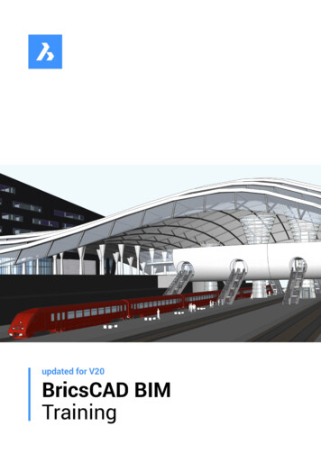
ModelingCreating the geometry of a model can be done in several ways. The main point to take away from this section is that no matter how youobtained the geometry, you can still use it later to add intelligence and data, and take it further in the BIM process. That is, as long as you’reworking with solids. Some possible ways to create the geometry are:1-Starting from an existing 2D layout, either by extruding objects upwards or by using Quickdraw-Starting from some 3D mass model and ‘sculpting’ your way to a more detailed model-Importing geometry from another file format such as .3dm or .stp-Using the RhinoInside plugin in BricsCAD BIM to be able to run Grasshopper scripts directly inside BricsCAD- Importing geometryThe following steps will give an example of how to import geometry and how it can be used to enrich your BIM Model.1.1Open Overall.dwg.You should see something like the image on theright. Hovering over the objects, you should noticethat the drawing consists of three Xref’s: one for eachbuilding volume and one for the site.Also, note that one of the building volumes iscurrently just a box. We will turn this into an actualbuilding later in the process.1.2Importing geometry1.Click the Bricsys button next to the Home tabon the Ribbon and click Import, or type in theIMPORT command.2.Select Canopy.3dm and click Open.3.A large canopy structure should appear inbetween the two buildings. This canopy consistsof solids, which means that the geometry can beused for further manipulation and informationcan be added to the geometry.13
2Sculpting a modelThe following steps will give an example of how to turn a simple volume study into actual building geometry. You willlearn some basic modeling tools along the way.2.1Manipulating the basic shape of an object1.Hover your cursor over the building that lookslike a box and in the Quad under Modify, clickOPEN XREF. Alternatively, open theAttachments Panel, right-click East andclick Open. If the Attachments Panel is notshowing in your panel stack, right-click anyempty space of the Ribbon and under Panels,enable Attachments.2.Now you should be able to see the box in aseparate drawing. We want to rotate some facesof the box to create a more interesting shape.To do this, make sure Face Detectionenabled.3.isHover over the end face of the box so that it ishighlighted in orange, and in the Quad underthe Model tab click ROTATE.4.A yellow widget appears that indicates therotation direction and axis. Move your cursorclose to the bottom edge of the face, until thewidget ‘rotates’ around that edge.5.Move your cursor to the right so that the facerotates ‘outwards’,type in 10 and hit Enter.6.Do the same for the top face:rotate it 10 degrees downward around its leftedge (see image).7.Do the same for the opposite end face of thebox: rotate it 15 degrees outward around itsbottom edge (see image).8.In the end, you should end up with a shapesimilar to the one shown in the final image (sideview).14
2.2Using Push/PullWe want to use some Push/Pull to create a moreinteresting shape. We want the shape to be similar tothe one of the West Building (see Overall.dwg).1.Rotate the camera so you can see the bottomside of the solid. We will be using the existinggrid as a basis for what we want to Push/Pull.2.Make sure Boundary Detection3.Move your cursor inside one of the grid cells andin the Quad under the Model tab, clickis enabled.PUSH/PULL4.Notice that moving the cursor will either pushthis area inside the solid or pull it out. You canleft-click to accept a value or type in a value andpress Enter if you want to be more precise.5.Undo the previous step; we want to Push/Pullmultiple portions at once, so we will select themall at once.6.Manually select the grid cells that arehighlighted in the image on the right. If youaccidentally select something else, useShift left-click do deselect that entity.7.Once you have these grid cells selected, usePUSH/PULLand push these faces inwardover a distance of 5500. Thus, you should endup with something similar as shown in the finalimage.2.3Using ShellCurrently, our building is still just a box: if we sectionthrough our building, we see that it is not hollow sono spaces can be made inside.1.In the Home tab of the Ribbon, click SECTION. Hover the cursor over one of the sidefaces until it is highlighted in orange, and leftclick. You should now be able to clip verticallythrough your model. Move the cursor inward sothat you’re clipping about halfway through themodel, and left-click.2.In the Modeling tab of the Ribbon, under SolidEditing, click SOLIDEDIT BODY SHELL.3.Select the solid and press Enter.4.When prompted the enter the shell offsetdistance, type in 300 and press Enter.5.Hit Enter twice more to exit the solid editingcommand.15
2.4Splitting the model into separate piecesThe solid is now hollow, but it still consists of 1 singleobject. In general, we want to split up the model soevery object is a separate entity. Otherwise, youmight run into problems when performingcommands like Bimify or when assigningcompositions. We can split up the model manuallyusing tools like Slice, but in this case, we’ll use anautomatic way to do this.1.Remove the section plane if you haven’t done soalready.2.Highlight the solid (not one of the faces), and inthe Quad under Model click SPLIT. Thiscommand will try to assume how to split themodel into separate solids.Note: this works best on simple geometry.3.We now have 18 solids. We need to clean up abit after using Split, because it did not doexactly what we wanted. As we can see on theimage on the right, the large sidewall (on eitherside) was also split into two pieces.4.In the Modeling tab of the Ribbon, under SolidEditing, click UNIONand select the twoside walls highlighted in the image.5.Do the same for the other side.6.As we can see on the second image, now theway the sidewall and back wall come together isnot uniform over the entire height of thebuilding. We can fix this using Push/Pull.7.Make sure Face Detectionis enabled.Hover over the edge and hit Tab a few timesuntil the end face of the sidewall is highlighted(see image).8.Use PUSH/PULLon this side face andsnap to any point on the back face. This shouldmake the butted connection uniform over theentire height.9.Do the same for the other side.10. Highlight the side wall solid and in the Quadunder Select tab, click HIDE ENTITIES11. Now that we can look inside, we see that thefloor slab has a hole in it where the supportstructure is located, and the slab itself is splitinto 4 separate pieces.12. In the Modeling tab of the Ribbon, under SolidEditing, click UNIONand select the fourparts of the floor slab, see image.16
13. To remove the hole in the slab, highlight any ofthe inner faces of the hole (make sure FaceDetectionis enabled), and in the Quadunder Model, click CONNECT WITH NEAREST2.5Creating some more interior walls and slabsLet’s change the connection between the upper floorslab and the wall highlighted in the image.14. Select both solids as highlighted in the image,and in the Quad under Model tab, click L-TYPESOLIDS CONNECTION15. Hit the Ctrl-key a few times until the connectionis shown as in the image, i.e. with the slabbutted against the wall instead of resting on topof it. Press Enter to accept.16. Highlight the top face of the wall (make sureFace Detectionis enabled), and in the Quadunder Model, click CONNECT WITH NEAREST. This should connect this wall with the roofslab, so we now have to separate rooms insideour building.17. We can create some more interior floor slabs.We can do this by simply copying the existingupper floor slab in the Z-direction, or we coulduse the BIM Copy tool18. Highlight the top face of the upper floor slaband in the Quad under Model tab, click BIMCOPY19. Move the cursor upward, type in 4000 and hitEnter20. Hit the Ctrl-key once so you go into ‘repeatedcopy’ mode; move your cursor until there are intotal 3 slabs above each other. Press Enter toexit the command.21. Notice that the two upper floor slabs are notconnected to the slanted end wall. We can againuse CONNECT WITH NEARESTfaces to solve this problem.on the end22. The BIM Copy tool can also be used onboundaries; Make sure Boundary Detectionis enabled and hover the cursor over theboundary highlighted in the image. This way youcan easily copy (parts of) walls and floor slabsaround your mode.17
3Starting from a 2D LayoutIn this section, we’ll create a building starting from a simple 2D layout, on the one hand using Quickdraw and on theother hand using more standard tools like Extrude.3.1Using Quickdraw to trace over an existing layout1.Open Office Building.dwg.2.Let’s start with the layout that is drawn along thecurrent UCS and that has simple on,click.4.A special cursor appears, indicatinglocations of the walls you will be creating.the5.Move the cursor close to one of the corners ofthe layout: you will see that it snaps to the lines.Position your cursor as shown in the image.6.Left-click: you are now drawing the first room.Move your cursor to the opposite (bottom righthand) corner of the layout and left-click again. Ifyou now rotate the camera, you’ll see that youcreated 4 walls and a slab.7.We can expand this room into an L-shapedroom by moving our cursor into the corner ofthe two walls highlighted in the image and leftclicking.Note that the walls you are snapping to arehighlighted in blue.8.By moving the cursor to the right, you will seethat a part of the right-hand wall becomes red.This means that we will be removing this part ofthe wall so that the room can be expanded intoan L-shaped room.9.Again, snap to the (other) bottom right-handcorner and left-click. You should now have an Lshaped room.10. We can use these steps to trace the interiorwalls as well. Note that the cursor becomes‘thinner’ as it snaps to these lines.11. Continue using Quickdraw until all of the linesof this layout have been traced over, and youhave every inner wall in place.12. Note that Quickdraw uses default values forslab thickness, room height etc. These defaultvalues can be found and changed in the settingsdialog.13. Also note that this Quickdraw tool can be usedin combination with direct modeling tools. Forthe sake of simplicity this section and theprevious section were split up but it is perfectlypossible to use hybrid methods.18
3.23.3Copying floors using Quickdraw1.Note that when Quickdraw is active, a little ‘ ’icon is displayed next to the building. Clicking itgives you three options:- Copy an entire floor- Copy only the outer walls of the floor- Create a flat roof2.Click the copy entire floor button four times soyou have a total of 5 floors.3.Finally, click the create roof button to finish thebuilding envelope.Creating stairsCreating stairs can be done in several ways; again,direct modeling is an option. However, it’s easier touse the dedicated stair tool.1.Activate a vertical section so you can see insidethe building.2.In the Home tab of the Ribbon, click STAIR3.A special cursor appears, similar to theQuickdraw cursor. This time it shows the firsttread and the direction of the stair. Hit the Ctrlkey to change the direction.4.Note that the cursor snaps to existing slabs andwalls. This allows for easy alignment withexisting objects.5.Move the cursor so that it snaps to the back walland is going ‘towards’ the left wall, as shown inthe image.6.A live preview of the stair is shown as you moveyour cursor over the slab beneath it. You canmake single-flight stairs, L-shaped stairs, and Ushaped stairs.7.Move your cursor along the left wall so that anL-shaped stair is previewed;8.Note that when the stair is created,automatically a hole is made in the upper slab.This is based on the HEADROOM setting. Moredefault settings can be found in the settingsdialog under BIM General Stair.9.Select the stair and open the Properties Panel.Under Parameters, you can find and alter itsgeometric properties, such as stair width or stepthickness.19
3.4Starting from non-rectilinear layoutsThe previous example consisted of a rectilinearlayout, aligned with the current UCS. The secondexample is not so simple: the outer walls are notaligned to the current UCS, the inner walls are notperpendicular and there is a cylindrical wall.Since Quickdraw only works in the current UCS, it’snot straightforward to use this tool for this particularsituation.1.Make sure Boundary Detectionis enabledand move your cursor inside the two lines of theouter walls. The boundary should behighlighted in green.2.In the Quad under Model tab, click SOLIDEXTRUDE.3.Move your cursor upward, enter a value of 3000and press Enter.4.Let’s also PUSH/PULLthe bottom face ofthe walls down over a distance of 250 mm sowe can easily create a floor slab.5.Now we can use the boundary between thelower edge of one of the walls and the layoutlines to SOLID EXTRUDEthe floor slab.You may need to construct part of the floor slabfirst and then use CONNECT WITH NEARESTso it connects properly with the cylindricalwall (see third image).6.Currently the outer walls are all constructed as1 solid; use SPLITseparate pieces.to split it up into7.Notice that the walls were split up into threeparts instead of five; the cylindrical wall was nottaken into account when splitting. We can stillsplit this up manually.8.Highlight the solid of the wall (see fourth image)and in the Quad under Model tab, clickMULTISLICE(careful: this icon look verysimilar to Slice by Object, which is lessstraightforward to use in this case).9.Multislice asks for a slicing plane: choose theface of the wall perpendicular to this part of thewall (in the image: the wall in the bottom lefthand corner). A blue slicing plane should appearthat indicated where you will slice the selectedobject.10. Snap to the point where the straight wall andthe curved wall come together, and left-click.Hit Enter to exit Multislice.20
11. Do the same in the perpendicular direction forthe other segment of the wall.12. In total we should now have 5 walls: fourstraight walls and one cylindrical.13. Make sure Boundary Detectionis enabledand move your cursor inside the two lines of theinterior walls. The boundary should behighlighted in green.14. In the Quad under Model tab, click SOLIDEXTRUDE.15. Move your cursor upward, enter a value of 3000and press Enter.16. Now use SPLITon these interior walls tosplit them into separate solids.17. Now we can simply copy this floor up usingCOPYor using the Manipulator.21
ComponentsYou will learn to use the components panel, insert objects into your model, create a simple nonparametric window and create windows and curtain walls on the fly.1Inserting components1.1Using the Components Panel1.Open East.dwg in the Components folder.2.On the right-hand side of your screen, open theComponents Panel. It should containseveral categories such as Windows and Doors. Ifit does not, click the little menu icon in the topright corner and enable Bricsys BIM Components.3.Note: aside from the BIM components also theso-called Bricsys Design Library is delivered withthe product. This library contains componentsused in mechanical design, such as standardparts and sheet metal features.4.The BIM components and Design Library aresaved under C:\Program Files\Bricsys\BricsCAD V20en US\UserDataCache\Support\en US.5.On Windows, when creating custom sys\Support\Bim\Components, or whichever path isspecified in the COMPONENTSPATH variablewhich can be found in the settings dialog.For Mac open the Finder, go to the Go tab andclick on ‘Go to folder ’ and type invar/Bricsys/Components.6.Left-clicking a category will open it. Left-clicking acomponent will allow you to insert it.7.Note: when inserting a component thecommand BMINSERT is la
The text in “bold blue” indicates BricsCAD BIM commands 4. The text in “bold black” is inserted and/or selected values 5. The exercises are in metric units (mm) Before beginning, make sure the following settings are enabled: - In the Status Bar (bottom