Transcription
CHAPTER 4Working with theAutodesk Revit ToolsYou can get only so far when allowing a computer application to placearchitectural components into a model. At some point, the application needsto be flexible enough to enable users to employ their own sets of drafting andmodifying tools, thus providing architects and designers with the freedom tocreate their own architecture and construction procedures. The Autodesk Revit Architecture program does provide the basic modify and edit commands, which are quite common in other drafting applications such asAutodesk AutoCAD software and MicroStation, but Revit does this witha little more flair and some differences in procedure as compared to a 2Ddrafting application.This chapter covers the following topics: The basic edit commands The Array command The Mirror command The Align tool The Split Element command The Trim command The Offset command Copy/Paste Creating the plans
166C h a p t e r 4 W o r k i n g w i t h t h e A u t o d e s k R e v i t To o l sThe Basic Edit CommandsIn this chapter, you’ll learn how to use the geometry you’ve already placed in themodel to build an actual working plan. As you manipulate the plan, all of theother views you made in Chapter 3, “Creating Views,” will reflect those changes.You’ll start with the edit commands.As with the previous chapter s, it ’s impor tant that you becomecomfortable with the material in this chapter. If you’re still not comfortable with the firstfew chapters, I recommend reviewing them now. You may pick up something you missedthe first time around and have a “lightbulb” moment.N O T EYou aren’t going to get very far in Revit without knowing the edit commands.Up to this point, I have been avoiding the edit commands with a few exceptions.There will be some overlap in some of the chapters, because many aspects ofRevit span multiple topics.The basic commands covered in this section are Move, Copy, and Rotate. Then, inthe following sections, you’ll move on to Array, Mirror, Align, Split Element, Offset,Copy/Paste, and Trim. Each command is as important as the next at this stage ofthe game. Some are obvious, whereas others can take some practice to master.The first command, Move, is one you’ll recognize from previous chapters.Move is probably the most heavily used command in Revit.The Move CommandThe Move command is generally used to create a copy of an item while deletingthe original item.Metric users should not type in mm or other metric abbreviations whenentering amounts suggested in the exercises. Revit won’t accept such abbreviations.Simply enter the number provided within the parentheses.N O T EBegin by finding the model you’re using to follow along. If you haven’t completed the previous chapter procedures, open the file called NER-4.rvt at thebook’s website, www.sybex.com/go/revit2017ner. Go to the Chapter 4 folderto find the file.To use the Move command, perform the following steps:1. Go to Level 1 under the Floor Plans category in the Project Browser.2. Zoom in on the west wing.
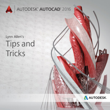
The Basic Edit Commands3. Select the south wall of the bump-out at the south side of the westwing, as shown in Figure 4.1.F I G U R E 4 . 1 : Select the wall to be moved. The Move button now appears on theRibbon.4. On the Modify Walls tab is the Move button (see Figure 4.1); click it.5. Now that the Move command is running, you see some choices onthe Options bar.Constrain If you select Constrain, you can move only at 0, 90,180, or 270 degrees.Disjoin If you select Disjoin, then when you move the wall, anywalls that are joined to it won’t be affected by the move. The wallwill lose its join.6. To start moving the item, you must first pick a base point for thecommand. Pick a point somewhere toward the middle of the wall, asshown in Figure 4.2.167
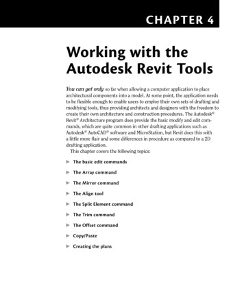
168C h a p t e r 4 W o r k i n g w i t h t h e A u t o d e s k R e v i t To o l sF I G U R E 4 . 2 : Choices on the Options bar. The first point has been picked, andthe wall is being moved up.7. After you pick this point, move your cursor straight up. You see a bluedimension. At this point, you have two choices: you can eyeball theincrement, or you can type the increment you want (see Figure 4.2).8. Type in the value 2 –6 (750 mm), and press Enter. The wall moves2 –6 (750 mm). Notice that the adjacent walls move with it (seeFigure 4.3). In Revit, there is no stretch command.F I G U R E 4 . 3 : Moving the wall 2 –6 (750 mm) also means that any adjoiningwalls will be adjusted along with it.
The Basic Edit CommandsRevit will accept a few different values for feet and fractional inches. Forexample, instead of typing 2 –6 (which Revit will accept), you can type 2 6. Just makesure you have a space between the 2 and the 6. Revit will accept that value. If there arefractional increments, you can type 2 6 1/2 , and Revit will accept the value. Or you cantype 2 –6 1/2 . (Metric users can just smile here.)T I PNow that Move is officially in the history books, it’s time to move on to Move’sclose cousin: the Copy command.The Copy CommandWhen you need to make duplicates of an item, Copy is your go-to player. TheCopy command works like the Move command, except that it leaves the initialitem intact. You can also create multiple copies if necessary.To start using the Copy command, follow these steps:1. Make sure you’re still in Floor Plan Level 1.2. Zoom and pan so you’re focused on the east wing, as shown inFigure 4.4.F I G U R E 4 . 4 : Creating a copy of the corridor wall3. Select the right corridor wall (see Figure 4.4).4. Click the Copy command on the Modify Walls tab.5. On the Options bar, check the Constrain toggle.169 You may be thinking,“But I used to typemy commands!” Well,you still can in Revit.If you type MVV, Revitlaunches the Movecommand.
170C h a p t e r 4 W o r k i n g w i t h t h e A u t o d e s k R e v i t To o l s6. Zoom in on the wall close to the midpoint of the selected wall andthe intersection of the horizontal wall that divides this portion of thebuilding (see Figure 4.4).7. If you hover your cursor in the center of the wall (not near the actualfinish faces, but the core of the wall), you’ll see a blue dotted centerline indicating that you’ve found the center of the wall. (If you’re having difficulty picking the item, change the detail level to Coarse.)Also, if you move your cursor to the right a little, you can positionit so that it picks up the horizontal wall’s centerline. After you pickup the horizontal wall’s centerline, the centerline for the vertical wallwill disappear. This is fine.When you see that you’re snapped to the endpoint of the horizontalwall, pick the point (see Figure 4.4).8. Move to the right until you pick up the midpoint of the horizontalwall. When you do, pick that point. If the midpoint doesn’t appear,type 22 –3 (6675 mm) or type SM for Snap Mid.9. Mirror the two walls to the south side of the corridor, as shown inFigure 4.5. The ends of the walls don’t meet. This is fine—you’llmodify these walls with the Trim command in a moment.F I G U R E 4 . 5 : The two walls copied, segmenting the spaces north and south ofthe corridor10. Save the model.
The Basic Edit CommandsThe next step is to rotate an item. Although the Rotate commandis a simple concept, Revit does have unique processes involved in thiscommand.The Rotate CommandThe Rotate command enables you to change the polar orientation of anitem or a set of items. This command may take a little practice to understand. The good thing, however, is that when you have experience with theRotate command, you’ll be better at other commands that share a similarprocess.To use the Rotate command, follow these steps:1. Open the Level 1 floor plan.2. Zoom in on the radial portion of the west wing, as shown inFigure 4.6.F I G U R E 4 . 6 : The radial portion of the west wing3. You’re going to add a new reference plane and rotate it by 45 . To doso, click Ref Plane in the Work Plane panel in the Architecture tab(see Figure 4.7).171
172C h a p t e r 4 W o r k i n g w i t h t h e A u t o d e s k R e v i t To o l sF I G U R E 4 . 7 : Establishing a reference plane4. In the Draw panel, click the Line button (it should be set current bydefault).5. For the first point, pick the center point of the radial wall, as shownin Figure 4.7.6. For the second point, pick a point horizontally to the right, outsidethe radial wall (again, see Figure 4.7).7. Press Esc twice, or click Modify.In Revit, sometimes finding the correct snap can be difficult. To overcome this,you can type the letter S followed by the first letter of the snap you want to use. Forexample, if you wanted to snap to the center of the arc wall, you would start the Ref Planecommand (any command works here, but I’m using a reference plane as an example), typeSC , place the cursor over the arc until the snap marker appears, and then click. This willsnap to the center.T I PBefore you rotate, be careful. Figure 4.7 shows the secondpoint extended past the radial wall, and that is where you generally want it. However,watch out for your snaps. When you pick the second point, be sure to zoom in on the area,ensuring that you aren’t inadvertently snapping to the wrong wall.W A R N I N G
The Basic Edit Commands173Now that you’ve added the reference plane, you can rotate it into place. (Yes,you could have just drawn it at a 45 angle, but you’re practicing the Rotatecommand here.) Follow these steps:1. Select the reference plane you just drew.2. On the Modify Reference Planes tab, click the Rotate button, asshown in Figure 4.8.F I G U R E 4 . 8 : The Rotate command is active for the specific item you’veselected.3. After you start the Rotate command, look back at the reference plane.Notice the blue dot in the middle of your line. Revit always calculatesthe center of an object (or group of objects) for the rotate point (seeFigure 4.9).F I G U R E 4 . 9 : Relocate the origin point for the rotation.4. On the Options bar, click the Place button, and select the end point ofthe reference plane. A temporary rotate icon appears, indicating thatyou can now move the blue dot (see Figure 4.9).You can start theRotate command bytyping RO, selectingthe item(s) to rotate,and then pressing thespacebar or Enter toplace the rotation icon.
174C h a p t e r 4 W o r k i n g w i t h t h e A u t o d e s k R e v i t To o l s5. With the rotate origin in the correct location, it’s rotate time! If youswivel your cursor around the reference plane, a line forms fromthe rotate origin to your cursor. This indicates that the origin isestablished. Now you need to pick two points. The first point youpick must be in line with the object you’re rotating. In this case,pick a point at the right endpoint of the reference plane, as shownin Figure 4.10.21F I G U R E 4 . 1 0 : To rotate an item, you must specify two points.6. When you move your cursor up, you see an angular dimension. Whenthat angular dimension gets to 45 , pick the second point (seeFigure 4.10).7. Press Esc.
The Array CommandAs you’re well aware, you’ll use the Rotate command quite frequently. Nowthat you have some experience with the Rotate command and know how Revitwants you to move the pivot point, the next command—Array—will be easy foryou to grasp.Rotatee OptionsWhile you’re in the Rotate command, don’t forget that you have options. Themost popular option is to create a copy of the item you’re rotating, as shown here:Another popular option is to specify an angle. This can be difficult, because thecorrect angle may be the opposite of what you think, resulting in your having toundo the command and then redo the rotation with a negative (–) value.The Array CommandWhen you need to create multiple duplicates of an item or a group of items, theArray command is the logical choice. The Array command in Revit functions ina fashion similar to the Rotate command. The similarities of the Array commandalso extend to the Array command in AutoCAD. You have two basic choices. Radiall, which enables you to array an item around a circle or an arc Linearr, which enables you to array an item in a straight line or at anangleLet’s look at the radial array first.Radial ArrayA radial array is based on a radius. If you need items to be arrayed in a circularmanner, the radial array is your best choice. Again, after you start the Arraycommand, don’t ignore the Options bar. It will guide you through most of thecommand.175
176C h a p t e r 4 W o r k i n g w i t h t h e A u t o d e s k R e v i t To o l sTo start using a radial array, follow these steps:1. Select the 45 reference plane.2. On the Modify Reference Planes tab, click the Array button, asshown in Figure 4.11.F I G U R E 4 . 1 1 : Select the item to be arrayed first, and then click the Arraybutton on the Modify Reference Planes tab.3. With the Array command active, some choices become available onthe Options bar, as shown in Figure 4.12. For this procedure, clickthe Radial button.F I G U R E 4 . 1 2 : Setting the options for the Radial array4. Select the Group And Associate check box.5. Set Number to 4.6. Click the Move To: Last button.7. With the options set, focus your attention on the object beingarrayed. Notice the familiar rotate icon.8. On the Options bar, click the Place button. It’s located next to theOrigin label, as shown in Figure 4.13.
The Array CommandF I G U R E 4 . 1 3 : Place the pivot icon on the endpoint of the item being arrayed.I Don’tt Want to Move Anything!The Move To: Last and the Move To: Second choices are somewhat misleading.You aren’t actually “moving” anything. If you choose Move To: Last, for example,Revit places an additional item in the last place you pick, keeping the first itemintact. Revit then divides the space between the two items evenly based on thenumber of items you specify in the options. If you specify four items, Revit stillhas two items left to divide.If you choose Move To: Second, Revit places an additional item at the secondpoint picked (just as with Move To: Last), but this time Revit adds additionalitems beyond the second item. The overall distance is calculated by the distancebetween the first two items.177
178C h a p t e r 4 W o r k i n g w i t h t h e A u t o d e s k R e v i t To o l s9. Click the center/endpoint of the reference plane (see Figure 4.13).10. With the pivot point in place, specify two points for the array. The firstpoint will be a point along the angle of the item being arrayed. Thesecond point will be a point along the angle on which you want to end.11. Pick the endpoint of the reference plane you’re arraying.12. Move your cursor down until you see 90 . Then pick the second point(see Figure 4.14).12F I G U R E 4 . 1 4 : Specifying the two angles for the radial array13. Pick (left-click) off into another part of the view. This establishes thearray. You should have four reference planes at this point, similar toFigure 4.15.14. Pick (left-click) one of the reference planes. You see a large, dashedbox surrounding the reference plane, and a temporary arc dimensionwith a blue number 4 at the quadrant. It may be obscured by the arc,as it is in Figure 4.15, but it’s there nonetheless.15. Click the number 4.
The Array CommandF I G U R E 4 . 1 5 : After the array is created, select one of the arrayed members.Notice that you can change the count.16. Change the count to 5. Press Enter, or click outside the array countfield to set the change.17. You now have five reference planes, as shown in Figure 4.16.F I G U R E 4 . 1 6 : You can control the number of items in an array group after youcreate the array.179
180C h a p t e r 4 W o r k i n g w i t h t h e A u t o d e s k R e v i t To o l sGetting the hang of radial arrays may take a few projects. The next arraytype, the linear array, follows the same concept as the radial array, but it’s morestraightforward. Yes, pun intended.Linear ArrayYou may want to create an array along a line, and you can do this in Revit.When you create a linear array,y you enjoy the same flexibility that you have witha radial array.The objective of this procedure is to create an array of windows along thenorth and south walls, on the west side of the building’s west wing. To do this,you’ll first need to establish two strong reference planes.To learn how to use the Linear array command, follow these steps:1. Zoom in on the northwest section of the west wing, as shown inFigure 4.17.F I G U R E 4 . 1 7 : Creating the reference plane2. Add two reference planes. You’ll use these reference planes to establish the ends of your window array. Go to the Ref Plane command onthe Work Plane panel of the Architecture tab.3. On the Draw panel, keep the Line icon active and add an offset of1 – 6 (450 mm)—Imperial users, remember that you can just type1 6 —on the Options bar.
The Array Command1814. Pick the corner of the radial wall, where it intersects the straight wall,for the first point of the reference plane, as shown in Figure 4.17.5. Pick a second point similar to that shown in Figure 4.17 to finish thereference plane.6. With the Ref Plane command still running, repeat the procedure forthe top of the wall. You want to pick the top, outside face of brick,avoiding the concrete ledge below, as shown in Figure 4.18.F I G U R E 4 . 1 8 : The two reference planes are established.Now you need to add a window based on the bottom reference plane. This window will then be arrayed up the wall to meet the northern reference plane. Hereare the steps:1. On the Architecture tab, click the Window button.2. Change Element Type to Fixed: 24 72 (610 mm 1829 mm).3. Place the window approximately where it’s shown in Figure 4.19. Youhave to move the window in alignment with the reference plane.4. Press the Esc key. If you’re drawing thereference plane andit keeps going abovethe wall (as opposedto below the wall), youcan tap the spacebar asyou’re drawing. Doingso flips the side ofthe wall on which theplane is being drawn.
182C h a p t e r 4 W o r k i n g w i t h t h e A u t o d e s k R e v i t To o l sF I G U R E 4 . 1 9 : Adding the window to be arrayed5. Select the window.6. On the Modify Windows tab, click the Move button.7. Move the window from the bottom, outside corner down to the reference plane, as shown in Figure 4.20.F I G U R E 4 . 2 0 : Moving the window into position
The Array Command8. Press Esc.9. Zoom out until you can see the entire wall.10. Select the window you just inserted into the wall.11. On the Modify Windows tab, click the Array button.12. On the Options bar, select Linear, as shown in Figure 4.21.F I G U R E 4 . 2 1 : Choosing the linear array options13. Select the Group And Associate check box (if it isn’t already selected).14. For Number, enter 4.15. Select Move To: Last.16. Pick the top endpoint of the bottom window.17. Move your cursor up the wall, and pick a point perpendicular to thetop reference plane, as shown in Figure 4.22.F I G U R E 4 . 2 2 : “Moving” the window to the top reference plane183
184C h a p t e r 4 W o r k i n g w i t h t h e A u t o d e s k R e v i t To o l s18. After you pick the second point, you’ll have to wait a moment; thenRevit evenly fills the void with the two additional windows. Revit alsogives you the option of adding more windows. Enter a value of 5, andpress Enter (see Figure 4.23).F I G U R E 4 . 2 3 : Changing the number of items in the array. You can alwayscome back to the arrayed group and change this value at any time.
The Mirror CommandAfter your items are grouped and arrayed, you can still move the enditem. Not only can you move the end item in the direction of the array, but you can move itlaterally to the array, causing a step in the array.N O T EWith the array completed, it’s time to duplicate your efforts on the otherside of the radial portion of this wall. As in CAD, at this point you have a fewchoices. You can repeat the Array command, copy the items, or mirror theitems.The Mirror CommandThe Mirror command works exactly as expected: it makes a copy of an objector a group of objects in the opposite orientation of the first item(s). The crucialpoint to remember is that you’ll need to specify a mirror plane.Although you simply couldn’t avoid using this command in previous chapters,you need to address and explore the Mirror command officially. The most useful aspect of the Mirror command is that if reference planes already exist in themodel, you can pick these planes to perform the mirror, as opposed to sketchinga new plane around which to mirror.The objective of the following example is to mirror the windows to the southside of the west wall.1. Zoom in on the windows you arrayed in the previous exercise.2. Select the windows starting from the upper-left corner to the lowerright corner, as shown in Figure 4.24. Remember, you can look at thebottom-right corner of the Revit window to verify that you have fivewindows selected.T I POops! You selected the wall. That’s OK. You don’t need to press Esc and startyour selection over. Simply hold down the Shift key and select the wall. It will becomedeselected.3. On the Modify tab, click the Mirror – Pick Axis button, as shown inFigure 4.25.185
186C h a p t e r 4 W o r k i n g w i t h t h e A u t o d e s k R e v i t To o l sF I G U R E 4 . 2 4 : Selecting the items to be mirrored. Make sure you don’t selectthe wall in which the windows reside.F I G U R E 4 . 2 5 : The Mirror buttons appear when you select an item.
The Mirror Command4. Position your cursor over the center reference plane that is part ofthe Radial array. When you pause, a tooltip indicates that you’reabout to select the reference plane. When you see this tooltip, selectthe reference plane, as shown in Figure 4.26.F I G U R E 4 . 2 6 : The line you’re going to pick is the reference plane shown here.5. Zoom out to check the placement of the windows. Don’t assume thateverything went as planned. Your Level 1 floor plan should resembleFigure 4.27.N O T EIf the mirror went wrong or you aren’t comfortable with the results, usethe Undo button and try again. Now is the time to practice!The two straight walls have windows, and it’s time to array some windowswithin the radial portion. The problem is, when you insert a window along aradius, you can’t snap it to the intersection of the reference plane and the wall.This is where the Align tool becomes critical.187 When you pick thereference plane, Revitmirrors the entiregroup of windows.
188C h a p t e r 4 W o r k i n g w i t h t h e A u t o d e s k R e v i t To o l sF I G U R E 4 . 2 7 : The finished west wallThe Align ToolYou’ll find yourself in situations where two items need to be aligned witheach other. The Align command is a great tool for accomplishing this task.It’s one of the most useful tools in Revit, and you’ll use it extensively. Overuseof this command isn’t possible! Because Align is a tool, you don’t have toselect an item first for this function to become available. You can select Alignat any time.
T h e A l i g n To o lTo practice using the Align tool, follow these steps:1. Zoom in on the radial portion of the west wall, as shown inFigure 4.28.F I G U R E 4 . 2 8 : Place the window approximately in the area shown here.2. On the Architecture tab, click the Window button.3. In the Type Selector, choose Fixed: 16 72 (406 mm 1829 mm).4. Place the window in the radial wall in a location similar to thatshown in Figure 4.28. Don’t attempt to eyeball the center of the window with the reference plane. As a matter of fact, purposely misalignthe window.5. On the Modify tab, click the Align button, as shown in Figure 4.29.189
190C h a p t e r 4 W o r k i n g w i t h t h e A u t o d e s k R e v i t To o l sF I G U R E 4 . 2 9 : Click the Align button on the Modify Place Window tab.6. The Align tool needs you to select two items. First, select theitem you want to align to; pick the reference plane as shown inFigure 4.30.12F I G U R E 4 . 3 0 : Choosing the items for alignment. Remember that you mustfirst choose the item you want to align to.7. Now you need to pick a point on the window: the centerline of thewindow. By looking at the window, you won’t see this line. Hoveryour cursor over the middle of the window, and a centerline becomeshighlighted. When you see this centerline, pick the window.
T h e A l i g n To o lThe window moves into alignment with the reference plane, asshown in Figure 4.31.F I G U R E 4 . 3 1 : The window is now in alignment with the reference plane.8. Press Esc, and then select the window.9. Pick the Array button on the Modify Windows tab.10. Create a radial array of the windows with a count of five (total). Youremember how, right? The only thing I want you to do differently isto uncheck Group And Associate on the Options bar. We’ll discussgroups in Bonus Chapter 4, “Project Collaboration,” available onlineat www.sybex.com/go/revit2017ner.Adding reference planes and working in a controlled environment istypical of Revit Architecture. You establish a reference plane, add a component, and thenexecute a command such as Array, Copy, or Move. Although it may seem like quite a fewsteps, you’re now accurately and deliberately placing items in your model. The accuracyyou apply here will propagate itself throughout the project in terms of elevations,sections, and drawing sheets.N O T E191
192C h a p t e r 4 W o r k i n g w i t h t h e A u t o d e s k R e v i t To o l sLet’s practice more with the Align tool. It’s one of the most important modifytools in the Revit arsenal, and I don’t want to understate its usefulness. Followalong with these steps:1. Zoom into the end of the corridor in the east wing of the building, asshown in Figure 4.32.F I G U R E 4 . 3 2 : Adding a double door to the east wing corridor2. On the Architecture tab, click the Door button.3. Place a Double Flush: 72 84 (1829 mm 2133 mm) door in theradial corridor wall, as shown in Figure 4.32. As when you placed thewindow along the reference plane in the preceding procedure, don’ttry to eyeball the correct alignment; you want to misalign the dooron purpose.4. Renumber the door 100A.5. On the Modify panel, click the Align button.6. Pick the horizontal reference plane.7. Pick the centerline of the door. When the reference plane is aligned,pause for a moment without pressing Esc. You see a little blue
T h e A l i g n To o lpadlock. If you can’t see it, zoom out a little. You can use this function to lock the alignment.Another nice feature of the Align command is that after your alignment iscomplete, you can physically lock the items together, allowing the two aligneditems to move as one.Locking an AlignmentAfter you’ve aligned the items, you’ll notice that small, blue padlock icon I justmentioned. In Revit, you can lock items together using the Align tool. Thisis both good and bad. It’s great in the sense that if the center reference planemoves for whatever reason, the door will also move. It’s bad in the sense that ifthe door moves, the center reference plane will also move.When you align an item and lock it, be sure this is what you want to do. It’ssimple: pick the padlock icon, as shown in Figure 4.33. You’re now aligned andlocked to the center reference plane.F I G U R E 4 . 3 3 : The door is now aligned and locked.193
194C h a p t e r 4 W o r k i n g w i t h t h e A u t o d e s k R e v i t To o l sThere will also be times when two items are already aligned and you just wantto lock the items together. To do this, you must still use the Align command toaccess the lock option.1. Zoom into the west side of the east wing at the corridor intersection.2. Start the Align command.3. Pick the centerline of the door at that end of the corridor.4. Pick the center reference plane.5. Pick the blue padlock to lock the doors to the center reference plane(see Figure 4.34).F I G U R E 4 . 3 4 : You can create a locked constraint by using the Align commandeven if the items were in alignment to begin with.Now that the Align command is out of the way, you can move on to the nextitem on the Modify tab: the Split Element command.The Split Element CommandThe Split Element command is the equivalent of the Break command inAutoCAD. You can use the Split Element command on walls and when you editan element in Sketch Mode.
The Split Element CommandThe objective of this procedure is to cut a notch out of a wall by using the EditProfile function.1. In the Project Browser, open the Sections (Building Section) calledWest Wing South Wall Section, as shown in Figure 4.35.F I G U R E 4 . 3 5 : Open the section called West Wing South Wall Section.2. Select the wall beyond, as shown in Figure 4.36.F I G U R E 4 . 3 6 : Select the wall beyond, and click the Edit Profile button on theModify Walls tab.3. On the Modify Walls tab, click the Edit Profile button (see Figure 4.36).After you select the Edit Profile option, you’re put into SketchMode. You know you’re in Sketch Mode because your Ribbon now hasa Mode panel with Finish Edit Mode and Cancel Edit Mode options195
196C h a p t e r 4 W o r k i n g w i t h t h e A u t o d e s k R e v i t To o l sthat you must select to return to the full model. Also, the wall you’veselected now consists of four magenta sketch lines, and the rest ofthe model is shaded into the background.4. On the Modify Walls Edit Profile tab, click the Split Element button, as shown in Figure 4.37.F I G U R E 4 . 3 7 : Select the Split Element button on the Modify Walls EditProfile tab.5. Look at your Options bar. Notice that you can specify that you wantto delete the inner segment. Select the Delete Inner Segment checkbox, as shown in Figure 4.38.F I G U R E 4 . 3 8 : To remove a segment of a line, you must use the Split Elementcommand and select Delete Inner Segment from the Options bar.6. Pick the intersection of the bottom magenta sketch line and theinside face of the left wall for the first split point (see Figure 4.38).
The Spli
Revit Arc hitecture program does provide the basic modify and edit com-mands, which are quite common in other drafting applications such as Autodesk A utoCAD so ftware an d MicroStation, but Revit does this with a little more fl air and some differenc