Transcription
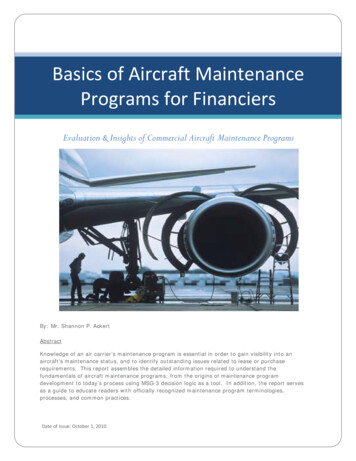
University of LiègeAerospace & Mechanical EngineeringAircraft DesignIntroduction to Structure LifeLudovic NoelsComputational & Multiscale Mechanics of Materials – CM3http://www.ltas-cm3.ulg.ac.be/Chemin des Chevreuils 1, B4000 LiègeL.Noels@ulg.ac.beAircraft Design – Structure Life
Total life design Design with stresses lower than– Elastic limit (sp0) or– Tensile strength (sTS) 1860, Wöhler– Technologist in the German railroad system– Studied the failure of railcar axless Failure occurred– After various times in service– At loads considerably lower than expectedw/21 cycle w/2t2 reversalsw/2w/2 Failure due to cyclic loading/unloading– « Total life » approach Empirical approach of fatigue2013-2014Aircraft Design – Structure Life2
Total life design Empirical approach: Total life– Life of a structure depends onsmax1 cycle 2 reversalssa Ds/2Ds smax-sminsmtsmin Minimal & maximal stresses: smin & smaxMean stress: sm (smax smin)/2Amplitude: sa Ds/2 (smax - smin)/2Load Ratio: R smin / smaxUnder particular environmental conditions (humidity, high temperature, ):– Frequency of cycles– Shape of cycles (sine, step, )2013-2014Aircraft Design – Structure Life3
Total life design First kind of total life approach: « stress life » approach– For structures experiencing (essentially) elastic deformations– For sm 0 & Nf identical cycles before failure For sa se (endurance limit):infinite life ( 107 cycles) For sa se, finite life With se [ 0.35 ; 0.5 ] sTSsa Ds/2seNf 1910, Basquin Law103104105106107– sf’ fatigue coefficient (mild steel Tamb : [1; 3 ] GPa)– b fatigue exponent (mild steel Tamb : [-0.1; -0.06])– Parameters resulting from experimental tests2013-2014Aircraft Design – Structure Life4
Total life design First kind of total life approach: « stress life » approach (2)– For sm 0 and Nf identical cycles, the maximal amplitude is corrected Soderbergconservative Goodman Gerberonly for alloys under tensions– Varying amplitude loads ni cycles of constant amplitudelead to a damagesa1,sm1sa2, sm2t 1945, Miner-Palmgren lawn1n2– Does not account for the sequence in which the cycles are applied2013-2014Aircraft Design – Structure Life5
Total life design Second kind of total life approach: « strain life » approach– For structures experiencing (essentially) Large plastic deformations Stress concentration High temperatures– For Nf identical cycles before failure 1954, Manson-Coffin– ef’ : fatigue ductility coefficient true fracture ductility (metals)– c : fatigue ductility coefficient exponent [-0.7 , -0.5] (metals)–plastic strain increment during the loading cycles2013-2014Aircraft Design – Structure Life6
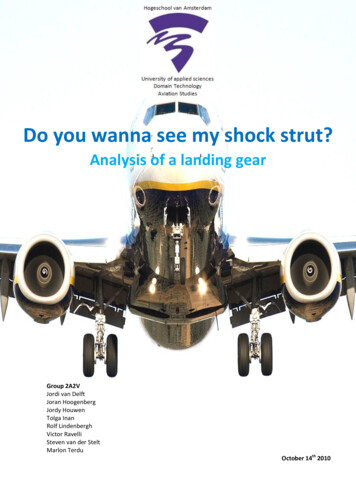
Design using total life approach 1952, De Havilland 106 Comet 1, UK (1)– First jetliner, 36 passengers, pressurized cabin (0.58 atm)– Wrong aerodynamics at high angle of attack (takeoff) 1953, 2 crashes: lift loss due to swept wing and air intakes inefficient– The fuselage was designed using total life approach 1952, a fuselage was tested against fatigue– Static loading at 1.12 atm, followed by– 10 000 cycles at 0.7 atm ( cabin pressurization at 0.58 atm)– Design issue 1953, India, crash during storm– « Structural failure » of the stabilizer– The pilot does not “feel” the forces due to the fully powered controls(hydraulically assisted)– Fatigue due to overstress ?2013-2014Aircraft Design – Structure Life7
Design using total life approach 1952, De Havilland 106 Comet 1, UK (2)– More design issues 1954, January, flight BOAC 781 Rome-Heathrow– Plane G-ALYP disintegrated above the sea– After 1300 flights– Autopsies of passengers’ lungsrevealed explosive decompression– Bomb? Turbine failure ?turbine rings with armor plates 1954, April, flight SAA 201 Rome-Cairo– Plane G-ALYY disintegrated 1954, April, reconstruction of plane ALYP fromthe recovered wreckages– Proof of fracture, but origin unknown 1954, April, test of fuselage ALYU– Water tank for pressurization cycles– Rupture at port window after only 3057pressurization cycles– Total life approach failed Fuselages failed well before the designlimit of 10000 cycles2013-2014Aircraft Design – Structure Life8
Design using total life approach 1952, De Havilland 106 Comet 1, UK (3)– 1954, August, ALYP roof retrieved from sea Origin of failure at the communication window Use of square riveted windows Punched riveting instead of drill rivetingExistence of initial defects The total life approach– Accounts for crack initiation in smooth specimen– Does not account for inherent defects Metal around initial defects could have hardened during the initial static test loadof the fatigue tested fuselage Production planes without this static test load Life time can be improved by– “Shoot peening”: surface bombarded by small spherical media Compression residual stresses in the surface layer Prevents crack initiation– Surface polishing (to remove cracks) 1958, Comet 3 et 4– Round windows glued– Fuselage thicker2013-2014Aircraft Design – Structure Life9
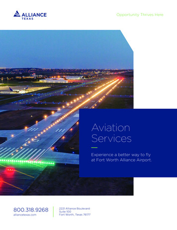
Other examples of fatigue failures 1985, B747 Japan Airline 123– 1978, tail touched the ground– Pressurization bulkhead repairedwith a single row of rivets– To be safe-life 2 rows are required(Boeing repair manual) 1988, B737, Aloha Airlines 243– 2 fuselage panels not correctly glued– Salt water inbetween– Rust and dilatation– Fatigue of the rivets These structures perished by fatigue– At load lower than ultimate load– After a large number of cycle2013-2014Aircraft Design – Structure Life10
Why fracture mechanics ? Limits of the total life approachy– Does not account for inherent defects What is happening when a defect is present ?– Example: Comet Theoretical stress concentration– Infinite plane with an ellipsoidal void (1913, Inglis)s syy2b– b 0smax syy2abreaks for s 0s – In contradiction with Griffith and Irwin experiments» Tensile strength depends on the crack size a and of surface energy gs Development of the fracture mechanics field– How can we predict failure when a crack exists ?– Microscopic observations for cycling loading Crack initiated at stress concentrations (nucleation)Crack growthFailure of the structure when the crack reaches a critical sizeHow can we model this?2013-2014Aircraft Design – Structure Life11x
Brittle / ductile fracture Mechanism of brittle failure In general inside the grains Preferred directions: low bonding Between the grains: corrosion, H2, – Rupture criterionsTSsp0True s– (Almost) no plastic deformations prior to the (macroscopic) failure– Cleavage: separation of crystallographic planes 1920, Griffith:True e2013-2014Aircraft Design – Structure Life12
Mechanism of ductile failure– Plastic deformations prior to (macroscopic)failure of the specimenTrue sBrittle / ductile fracturesTS Dislocations motionvoid nucleationsp0around inclusionsmicro cavity coalescencecrack growth Is Griffith criterionstill correct? 1950, Irwin, the plastic work at the crack tipshould be added to the surface energy:2013-2014Aircraft Design – Structure LifeTrue e13
Linear Elastic Fracture Mechanics (LEFM) Singularity at crack tip for linear and elastic materials– 1957, Irwin, 3 fracture modesMode IMode IIMode III(opening)(sliding)(shearing)yxyyzxxzzyr Boundary conditionsqxMode Ior2013-2014Mode IIMode IIIorAircraft Design – Structure Life14
Linear Elastic Fracture Mechanics (LEFM) Singularity at crack tip for linear and elastic materials (2)– Asymptotic solutions (Airy functions, see fracture mechanics classes)Mode IMode IIMode IIIywith for plane s& plane er Introduction of the Stress Intensity Factors - SIF (Pa m1/2)x Ki are dependent on both the loading and the geometry2013-2014Aircraft Design – Structure Lifeq15
Linear Elastic Fracture Mechanics (LEFM) New failure criterion– 1957, Irwin, crack propagation smax If Ki KiCs is irrelevantcrack growth– Toughness (ténacité) KIc Steel, Al, : see figures Concrete: 0.2 - 1.4 MPa m1/2(brittle aft Design – Structure Life16
Linear Elastic Fracture Mechanics (LEFM) Stress Intensity Factor (SIF)y– Computation of the SIFs Kis Analytical (crack 2a in an infinite plane)s xs 2a For other geometries or loadingss yt x 2abi obtained by– Superposition– FEM– Energy approach» Related to Griffith’s workt yt x2a» See next slides– For 2 loadings a & b: KI KIa KIb– BUT for 2 modes K KI KII2013-2014Aircraft Design – Structure Life17t
Linear Elastic Fracture Mechanics (LEFM) Energy approachyr– Mode Iqx Initial crack 2aDaaysyy 0,syy 0,uy 0uy 0 Crack grows to 2(a Da)rqxasyy 0,uy 0Dasyy 0,uy 0 Energy is needed for crack to grow by 2Da as there is a work done by syy( x4 as it is for x 0, x 0 & for y 0, y 0)2013-2014Aircraft Design – Structure Life18
Linear Elastic Fracture Mechanics (LEFM) Energy approach (2)syyeint– Mode I Energy needed for crack to grow by Dauy Assumption: syy linear in terms of uy Change of variable G : energy release rate for a straight ahead growth– The crack has been assumed lying in an infinite plane. Butstill holds for other expressions of KI (see fracture mechanics)2013-2014Aircraft Design – Structure Life19
Linear Elastic Fracture Mechanics (LEFM) Energy approach (3)– 1920, Griffith, energy conservation: Total energy E is the sum of the internal (elastic) energy Eint with the energyG needed to create surfaces A If gs is the surface energy (material property of brittle material)A crack creates 2surfaces Acrack growth if– Mode I, infinite planeDepend on thecrack size Strength Glass: Gc 2 gs 2 Jm-2, E 60 GPa Steel: Gc plast. dissipation 200 kJm-2, E 210 GPa– Straight ahead propagation for general loading Proceeding as for mode I:crack growth if2013-2014Aircraft Design – Structure Life20
Brittle / ductile fracture Example: Liberty ships (WWII)– Steel at low T : brittlewith gs 3400 J m-2 – Steel at room T : ductilewith 2gs Wpl 200 kJ m-2 – Use of low-grade steel In cold weather:DBTT water temperature When put in water existingcracks lead to failure 30% of the liberty shipssuffered from fracture2013-2014Aircraft Design – Structure Life21
Linear Elastic Fracture Mechanics (LEFM) Energy approach: J-integral– Energy release rate Straight ahead propagation for linear elasticity– Should be related to the energy flowing toward the crack tip J-integralBy– Defined even for non-linear materialsrqD– Is path independent if the contourxG embeds a straight crack tipa– BUT no assumption on subsequentGgrowth direction– If crack grows straight aheadG J– If linear elasticity– Can be extended to plasticity if no unloading (see fracture mechanics) Advantages– Efficient numerical computation of the SIFs– Useful for non perfectly brittle materials2013-2014Aircraft Design – Structure Life22
Linear Elastic Fracture Mechanics (LEFM) Direction of crack grow– Assumptions: the crack will grow in the direction where the SIF related tomode I in the new frame is maximal Crack growth ifwith– From direction of loading, one can compute the propagation directionys q*x2a2013-2014sqq /KIr1/2b* er20(2 r)eqqs b* 15 b* 30 b* 45 b* 60 b* 90 q*4-2-4Maximum is for q 0-100Aircraft Design – Structure Life0qq [ ][deg.]10023
Cyclic loading Fatigue failure– Tests performed with different DP Pmax - Pmin– Nucleation: cracks initiated for K Kc Surface: deformations result fromdislocations motion along slip planesPaPN cyclesPmaxPmin Can also happen around abulk defect2013-2014Aircraft Design – Structure Life24
Cyclic loading Fatigue failure (2)Perfect crystal– Stage I fatigue crack growth: Along a slip plane– Stage II fatigue crack growth:Crack growth Across several grains– Along a slip plane in each grain– Straight ahead macroscopically Striation of the failure surface:corresponds to the cycles2013-2014Aircraft Design – Structure Life25
Cyclic loading Fatigue failure (3)P– SSY assumption Tests: conditioning parameters– DP &– Pmin / Pmax Therefore fatigue failurecan be described by– DK Kmax- Kmin &– R Kmin/Kmaxa (cm)54DP2 DP1a3RuptureDP1P212345Structure inspectionpossible (for DP1)6Nf (105)7Rapid crackgrowthInterval of striations There is DKth such that if DK DKth:– The crack has a growth rate lower than one atomic spacing per cycle(statistical value)– Dormant crack2013-2014Aircraft Design – Structure Life26
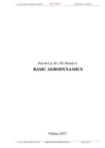
Cyclic loadingda / d Nf Crack growth rate– Zone I Stage I fatigue crack growthDKth depends on RZone IZone IIIZone IIRm– Zone II Stage II fatigue crack growth: striation 1963, Paris-Erdogan1logDKDKth– Depends on the geometry, the loading, the frequency– Steel: DKth 2-5 MPa m1/2 , C 0.07-0.11 10-11 [m (MPa m1/2)-m], m 4– Steel in sea water: DKth 1-1.5 MPa m1/2, C 1.6 10-11 [idem], Be careful: K depends on am 3.3integration required to get a(Nf)– Mode I :– Zone III Rapid crack growth until failureStatic behavior (cleavage) due to the effect of Kmax(a)There is failure once af is reached, with af such that Kmax(af) Kc2013-2014Aircraft Design – Structure Life27
Fatigue design « Infinite life design »– sa se: « infinite » life– Economically deficient « Safe life design »– No crack before a determined number of cycles At the end of the expected life the componentis changed even if no failure has occurred Emphasis on prevention of crack initiation Approach theoretical in nature– Assumes initial crack free structures– Use of sa – Nf curves (stress life) Add factor of safety– Components of rotating structures vibratingwith the flow cycles (blades) Once cracks form, the remaining life is very shortdue to the high frequency of loading2013-2014Aircraft Design – Structure Life28
Fatigue design « Fail safe design »– Even if an individual member of a component fails, there should be sufficientstructural integrity to operate safely– Load paths and crack arresters– Mandate periodic inspection– Accent on crack growth rather than crack initiation– Example: 1988, B737, Aloha Airlines 243 2 fuselage plates not gluedSea waterrust and volume increasedFatigue of the rivetsThe crack followed a predefinedpath allowing a safe operation2013-2014Aircraft Design – Structure Life29
Fatigue design « Damage tolerant design »– Assume cracks are present from the beginning of service– Characterize the significance of fatigue cracks on structural performance Control initial crack sizes throughmanufacturing processes and(non-destructive) inspections Estimate crack growth rates duringservice (Paris-Erdogan) & planconservative inspection intervals(e.g. every so many years, numberof flights) Verify crack growth duringthese inspections Predict end of life (af) Remove old structures from servicebefore predicted end-of-life (fracture) orimplement repair-rehabilitation strategy– Non-destructive inspections Optical X-rays Ultrasonic (reflection on crack surface)2013-2014Aircraft Design – Structure Life30
References Lecture notes– Lecture Notes on Fracture Mechanics, Alan T. Zehnder, Cornell University,Ithaca,– Other references– « on-line » Fracture Mechanics, Piet Schreurs, TUe,http://www.mate.tue.nl/ piet/edu/frm/sht/bmsht.html– Book Fracture Mechanics: Fundamentals and applications, D. T. Anderson. CRC press,1991.2013-2014Aircraft Design – Structure Life31
Aircraft Design Introduction to Structure Life Aircraft Design – Structure Life . 1954, January, flight BOAC 781 Rome-Heathrow – Plane G-ALYP disintegrated above the sea – After 1300 flights . – Asymptotic solutions (Airy functi