Transcription
version: 9/30/2009Building Performance Simulation for Designers - EnergyDesignBuilder // EnergyPlus‘Tutorial #1’G tti StGettingStartedt dGEOMETRYLOADSDiego Ibarra ChristophCReinhartHarvard Graduate School of DesignRESULTS
version: 9/30/2009OVERVIEWThis documentThidt isi a guideid forf buildingb ildi energy performancefsimulation beginners. Its focus audience are designers interestedin studying the effect of early design decisions such a orientation,shape and façade layout on the energy efficiency of their projects.Throughout the document we will be using DesignBuilder/EnergyPlusgyas our simulation tool. The document will teach yyouhow to:Set up DesignBuilder on your WINDOWSTM PC;Build and maintain a simple model in DesignBuilder;Carry out a heating and cooling load analysis of themodel and calculate its annual energy use for heating,lighting and coolingcooling.
version: 9/30/2009OVERVIEWBuilding Energy Performance SimulationA buildings is a complex thermodynamic object thataccommodates constantly changing energy flows between thedifferent thermal zones within the building and the outside.The two main componentspof the buildingg energygy simulation modelare the building fabric and content (walls, floors, ceilings,occupants and equipment) and the plant components (HAVCequipment and other environmental control systems).Due to the complexity of a building model, computer simulationscan analyzey the effects of different ECMs ((Energygy ConservationMeasures) and their complex interactions more efficiently,comprehensively and accurately that any other available method.1INFO1-M Kaplan and P Caner, Guidelines for Energy Simulation of Commercial Buildings.Report for Bonneville Power Administration (DE-FC79-85BP26683). 1992.
version: 9/30/2009OVERVIEWSimulation Engine vsvs. GUIMost building energy simulation programs come with a graphicaluser interface (GUI) as well as the actual simulation engineengine. Theformer is used to prepare simulation input files for the latter and todisplay simulation results once a simulation is complete.The developers of simulation engines and GUIs often work fordifferent companies with the engine being developed at publicorganizations (government lab & universities) whereas GUIs aremore often developed by commercial vendors. As a result therecan be several GUIs for the same simulation engine.While the choice of GUI determines the ease of use if a simulationprogram, it is ultimately the engine that determines how reliablesimulation results areare. A great GUI with a weak engine cannot yieldreliable results!
version: 9/30/2009OVERVIEWWe will be using EnergyPlus as the simulation engineEnergyPlusgyis the U.S. Departments of Energy’sgy 3rd ggenerationdynamic building energy simulation engine for modeling building,heating, cooling, lighting, ventilating and other energy flows.2The program was developed during the nineties and is anamalgamation of the BLAST and DOE-2 simulation engines. Apartfrom energy use,use the program can be used for load calculationsand to model natural ventilation, photovoltaic systems, thermalcomfort, water use, green roofs and other ECMs.INFOEnergyPlus can be downloaded from www.eere.energy.gov/buildings/energyplus/. The programcomes with ample documentations but without a GUI. EnergyPlus’ capabilities are constantly beingf th expandedfurtherd d so ththatt more recentt modulesd l mighti ht nott beb accessibleibl ththroughh any GUIGUI. AAs aresult advanced users often start editing their models manually using a text editor. Once anymanual changes have been made to a model one usually cannot go back to the GUI.
version: 9/30/2009OVERVIEWOtherOe reasonseaso s foro ususingg EnergyPluse gy usIt is a ‘Qualified Computer Software’ for Calculating EnergySavingsg for Purposespof the Energy-EfficientgyCommercial BuildinggTax Deduction under Internal Revenue Code §179D.Expert users can get access to the source code allowing for thirdparty validation which adds to the software’s credibility and longterm reliability.EnergyPlusEPl hhas bbeen validatedlid t d underd ththe comparativeti StStandardd dMethod of Test for the Evaluation of Building Energy AnalysisComputer Programs BESTEST/ASHARE STD 140.INFOTo find a list of qualified computer software for calculating commercial building energy and power costsavings that meet federal tax incentive requirements under Internal Revenue Service (IRS) go to:http://www1 eere energy gov/buildings/qualified software d software.htmlThe BESTEST (Building Energy Simulation TEST) is a comparative set of tests which has become one of theindustry’s most accepted methods to validate and test the simulation capabilities of the exterior envelopeportions of building energy simulation programs. More information at http://gundog.lbl.gov/dirpubs/rio4.pdf
version: 9/30/2009OVERVIEWOtherOe reasonseaso s foro ususingg EnergyPluse gy usIt is a ‘Qualified Computer Software’ for Calculating EnergySavingsg for Purposespof the Energy-EfficientgyCommercial BuildinggTax Deduction under Internal Revenue Code §179D.Expert users can get access to the source code allowing for thirdparty validation which adds to the software’s credibility and longterm reliability.EnergyPlusEPl hhas bbeen validatedlid t d underd ththe comparativeti StStandardd dMethod of Test for the Evaluation of Building Energy AnalysisComputer Programs BESTEST/ASHARE STD 140.INFOTo find a list of qualified computer software for calculating commercial building energy and power costsavings that meet federal tax incentive requirements under Internal Revenue Service (IRS) go to:http://www1 eere energy gov/buildings/qualified software d software.htmlThe BESTEST (Building Energy Simulation TEST) is a comparative set of tests which has become one of theindustry’s most accepted methods to validate and test the simulation capabilities of the exterior envelopeportions of building energy simulation programs. More information at http://gundog.lbl.gov/dirpubs/rio4.pdf
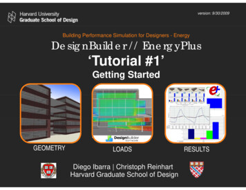
version: 9/30/2009OVERVIEWEnergygy Plus’Integrated Solution ManagerBy using an integrated solutiontechnique, EnergyPlus overcomesthe most serious deficiency of theBLAST and DOE-2 sequentialsimulations– inaccurate spacetemperature predication due to nofeedback from the HVAC module tothe loads calculations. Accurateprediction of space temperatures iscruciali l tto energy efficientffi i t systemtengineering, occupant comfort,occupant health, system size, plantsize.Source: D.B. Crawley et al. / Energy and Buildings 33 (2001) 319 331, and Getting Started with Energy Plus, (2007).INFOLoads calculated (by the heat and mass balance engine) are passed to the building systems simulation module.The building systems simulation module calculates heating and cooling system and plant and electrical systemresponse. Feedback from the building systems simulation module on loads not met is reflected in the next timestep of the load calculations in adjusted space temperatures if necessary, and not just reported as unmet hours.
version: 9/30/2009OVERVIEWChoosing a GUI for EnergyPlus?Simulation engineGraphical User InterfacesINFOA number of GUIs are currently available for EnergyPlus.EnergyPlus Among those GUIs Ecotect,Ecotect Google Sketchup(Energy Design Plug-in) and DesignBuilder mare specifically geared towards users with a background indesign as opposed to engineering. A list of all the available GUIs for EnergyPlus can be found /
version: 9/30/2009OVERVIEWWhy DesignBuilder?We choseWhDDesignBuilderi B ild ththe ttooll ffor thithis ttutorialt i l as wefound it to be a mature product which offers flexiblegeometry input and extensive material libraries and loadprofiles.EnergyPlusgyis integratedgwithin DesignBuilder’sgenvironment which allows you to carry out completesimulations without leaving the interface.INFOWhen bringing whole-building performance simulation closer to designers it is key to make theprocess of setting up a model and populating it with technical data as simple as possible withoutcompromising accuracy or rigor. Reliable data templates of libraries and components (constructions,materials, schedules, HVAC system, activity profiles, etc) are extremely important in this process asthey help designers set up their models in a comprehensive and transparent way.
version: 9/30/2009OVERVIEWWhy DesignBuilder?Simulation results can be effectively displayed andanalyzed. simulation data in a comprehensive manner.DesignBuilder has quality control procedures which assurethe accuracy of the results in comparison the stand-aloneEnergyPlus engine. e.g. As EnergyPlus, it has beentested under the comparative Standard MethodBESTEST/ASHARE STD 140140.
version: 9/30/2009OVERVIEWSoftware LimitationsAn advanced user might find the EnergyPlus simulationcapabilities that are accessible form the DesignBuilder GUIlimiting. In this case a user can export a DesignBuildermodel into EnergyPlus ASCII files. Unfortunately, it iscurrently not possible to import a modified model back intoDesignBuilder.DesignBuilderThere are limitation for inputting complex geometry (e.g.geometries defined through smooth functions / free forms)
version: 9/30/2009INDEXSET-UPBUILDING A MODELRUN A SIMULATIONANALYZE RESULTSINFOIt is recommended that you work through the four sections in the order provided. Further informationdistributed throughout the text.can be accessed through
version: 9/30/2009SET - UPFollow the instructions outlined below to set-up your computer.Make sure to pay close attention to all the steps and execute themcarefully.yYou may download a FREE 30-day evaluation version of the latestDesignBuilder version from the ‘DesignBuilder Software’ website. Thisdocument is based on DesignBuilder v.1.6.2.0004v 1 6 2 0004 BETA (release esignBuildergSoftware requiresqyyou to pprovide some ggeneral information about yyourself before yyoucan download the evaluation version. You must be logged in before attempting to download. If you donot have a login and password, you will have to register first.
version: 9/30/2009SET - UPIf you have a previous version of DesignBuilder installed you must firstuninstall it from the Windows Control Panel ‘Add or remove programs’before installing a new version. DesignBuilder is designed for WindowsVista, Windows XP SP2 and Windows 2000. Windows 95, 98, ME, NT arenot supported.The file you have to download is a .EXE file. Save it into any folder on yourPC and double click on it. Follow the on-screen instructions. The completeinstallation takes about one or two minutes. You may delete the file after theinstallation is completed.Folder directory preferences: It is recommended that you use the defaultDesignBuilder installation location on your PC which is C:\ ProgramFiles\DesignBuilder (see note below).INFOYou must be logged on with Administrator privileges to the machine on which you are installingDesignBuilder. Otherwise you will receive error messages during installation and the software will notrun.
version: 9/30/2009SET - UPWhen using DesignBuilder with Windows Vista you should ensure thatWindows XP SP2 compatibility has been set. You should also check theDisable desktop composition'composition to switch off the 'Aero'Aero interface effect.'DisableWithout these changes the DesignBuilder screen does not refresh correctly.These settings need to be changed before you run DesignBuilder for thefirst time. ((see note below))Many of the early graphics adapter drivers written for Vista have bugspreventing DesignBuilder from loading at all. It is recommended youupgrade your graphic adapter drivers.INFOTo set DesignBuilder to run in compatibility for Windows XP SP2, right click on the DesignBuilder icon from thestart menu and select "Properties". Then click on the Compatibility tab and check "Run this program incompatibility mode for:" and select Windows XP SP2 if it is not already set. Also check the 'Disable desktopcomposition' to switch off the 'Aero'compositionAero interface effecteffect. Many recent ATI Radeon graphics cards are not compatiblewith DesignBuilder because of OpenGL compatibility issues. More information about compatibility relatedproblems can be found at http://www.designbuilder.co.uk
version: 9/30/2009SET - UPgyygpyThe EnergyPlusdynamicsimulation enginesis completelyintegrated into DesignBuilder and there is no need to install itseparately. When you install DesignBuilder, the installationpackage installs EnergyPlus automatically into a folder under thesame directory. e.g. C:\ Program Files\ DesignBuilder\EnergyPlus.This document is based on DesignBuilderv.1.6.2.0004 BETA (07/31/08), which workswith EnergyPlusv2EnergyPlusv2.2.0.0252 0 025 engine.engineINFOWith time,, as yyou become an more advanced user yyou mayy want to install EnergyPlusgyseparatelypy toreview the files in detail in a text based option with EnergyPlus’ IDF editor. In that case you candownload EnergyPlus from http://www.eere.energy.gov/buildings/energyplus/
version: 9/30/2009SET - UPCustomizing DesignBuilder - Selecting a Unit SystemDesignBuilder can be used with either metric (SI) or imperial(IP) units. Because the most databases that come with theprogram were originally configured in SI units, IP users mayfind of some of the default assumptions awkward. Forexample even thought the glazingexample,glazing’ss U-values are displayed in(Btu/h*ft2*F), the names and decryptions associated withevery glazing are still displayed in mm.
version: 9/30/2009SET - UPCustomizing DesignBuilder - Selecting a Unit SystemThe firstThfi t timetiyou run DesignBuilderD i B ild a windowi dwillill pop up askingkiyou which UNIT SYSTEM you want to use: IP (Inch-Pound) or SI(International System). For the purpose of this document, to thequestion: “Do you want to use IP Units?” Click “NO”.INFOAs the pop up window states, you can later switch between IP and SI units at any time. (In the next pageyou can see how to switch between SI and IP units).
version: 9/30/2009Customizing DesignBuilder - Selecting a Unit System1.To switch between SI and IPunits go to “Tools” “ProgramOptions”2.Under “Units”Units you find:1-Metric (SI) and2-Inch-Pound (IP)
version: 9/30/2009BUILDING A MODELNow that you have downloaded and installed DesignBuilder/EnergyPlus, follow the steps outlined below to learn how to build asimple model and to carry out a building energy performancesimulation.At the end of this section you should be able to:Understand the basis of DesignBuilder’s userinterface and it’s data organization modelBuild a simplep modelINFOPlease finish reading this whole section before you go on and watch the DesignBuilder online tutorials.
version: 9/30/2009BUILDING A MODELWe suggest you first work through Tutorial #1 (User Interface) onthe DesignBuilder website. The tutorial is an excellent way tofamiliarize yourself with the interface and its capabilitiescapabilities. Followeach step carefully as we will continue to work on the file you createin Tutorial #1.TUTORIAL #1Tutorial number one will introduce yyou to the overall layoutyof the GUI and to the construction of building models. Itshows you how to create a new project, describes thebasic drawing tools and briefly talks about data hierarchieswithin EnergyPlus.INFOPlease review the next 4 slides before you work through Tutorial #1.
version: 9/30/2009BUILDING A MODELDesignBuilder Software has made these tutorials available online.You can either watch them online or download them to yourcomputert tot watcht h themthoffline.ffliTo watch them online, launch DesignBuilder, from theWINDOWSTM ‘START’ menu, choose ‘PROGRAMS’ ‘DesignBuilder’ ‘DesignBuilder’, then click in the link“web tutorials” that yyou will find at the center rightg of yyourscreen under “other tools”. This will launch your webbrowser directly to the tutorial’s page.To download the tutorials go to DesignBuilder’s webpage:http://www.designbuilder.co.uk, then to “Downloads” andthen “Tutorial”Tutorial .
version: 9/30/2009BUILDING A MODELPlease note that the tutorials are based on an older version ofDesignBuilder. This will make your model and screen look slightlydiffdifferentt thanth theth ones shownhiin ththe ttutorial.t i l ThThe olderld versionsioffDesignBuilder have less options in the menus and tabs and havedifferent default templates. For example, the default value for wallopenings was changed from 30% to 40% in version 1.6.004.It is important that you keep all of the defaults as set inyour current version and that you only modify theelements or parameters mentioned in the Tutorial.
version: 9/30/2009BUILDING A MODELSelecting a Template1.When askedWhk d to modifydifthe “Activity” of themeeting room located inthe “Ground floor”, clicki thinthe “b“browse”” ttabb ttoselect a different activitytemplate.2.Under the ‘Select activitytemplate’ menu, choosethe most appropriatetemplate for the space. i.e.‘Office MeetRm’.INFONote that templates (activity, schedules, constructions, etc., might vary between different versions.
version: 9/30/2009BUILDING A MODELInputting GeometryOnce you are finishedOfi i h d withithTutorial #1, you should have amodel that looks similar to this:‘Edit’ Tab‘Visualize’ TabPlease start with Tutorial #1 now.INFO
version: 9/30/2009BUILDING A MODELMODEL DATA HIERARCHY & DATA INHERITANCENow that you have watched Tutorial#1 and familiarized yourself withthe interface, we will further explainof how data inputsome keyy aspectsppis organized in DesignBuilder / e DesignBuilder, same as e ,DesignBuilder follows a ‘modelmodeldata hierarchy’. DesignBuilder further uses‘data inheritance’ through categoriesg yyou to automaticallyy ppopulatepsuballowingcategories. This way information is passedautomatically from higher category levels tolower category level making data inputfaster and more reliable (see the next slide).
version: 9/30/2009BUILDING A MODELDefault data is inheritedfrom the level above in thehierarchy,blockdatahih so blkdt iisinherited from buildinglevel, zone data isinherited from block dataand surface data fromzone data. When youychange a setting for acategory this change is‘inherited’inherited by all lowerlevels within the category.INFOThis arrangement allows you to either make settings at the building or block level. A selection for awall type at the building level will affect all walls within the building whereas a selection at the blocklevel will only affect the walls within that particular block.
version: 9/30/2009BUILDING A MODELConstruction and windowto-wall-ratios defaultvalues are inherited downto the surface level wherethe data is actually usedin the calculations.INFOFor example, it is the External wall construction model data at the surface level that defines the constructionused for that external wall. The External wall model data set at zone, block and building level has no effecton the model (other than providing a default values for lower lying levels).Most data at the building level is “user data” as buildings do not inherit their data from the site level. Allopenings inherit their data from the surface level.
version: 9/30/2009BUILDING A MODELMODEL DATA HIERARCHY & DATA INHERITANCE
version: 9/30/2009SIMULATIONNow that you know how to build a simple model, we suggest thatyou work through Tutorial #2 (Simulations). We will afterwardsreview your simulation results from the tutorial with youyou.TUTORIAL #2Tutorial number two will show you how to run designcalculations for winter and summer design conditionsanddhhow tto carry outt an annuall simulationi l ti usingi ttypicali lweather data for your site. The latter provides anestimate of a building‘s overall annual fuel consumption.INFOThe following slides provide additional informationabout simulation basics and additional settings.
version: 9/30/2009SIMULATIONHeating Design CalculationA heating design calculation is performed to investigate abuilding’s behavior under extreme weather conditions.Calculation results are typically used to size heatingsystems and their componentscomponents.INFOThe weather conditions used during a heating design calculation are set according to the building location. Thedesigner may select the "severity" of weather that he or she deems appropriate. Typical heating designtemperatures lie in the 99th or 99.6th percentile of all temperatures that typical occur at a site throughout theyear, i.e. 99% or 99.6% of the time it is warmer than the heating design temperature.Heating design calculations are carried out under Steady State (SS) conditions (stable temperatures over aseveral-hour period), which means that thermal mass effects are ignored. The calculations assume worst caseconditions including no solar gains, no internal gains (lighting, equipment, occupancy, etc) and design conditionsfor wind speed and direction. The resulting “design heat loss” (the sum of all heat flows out of a building) isfurther multiplied by a “sizingsizing factor”factor to determine the “designdesign heating load”load (the capacity of heating equipmentrequired to offset all heat losses). See also ASHRAE Handbook of Fundamentals, 2001 (ISBN 1-883413-87-7)TC.29.
version: 9/30/2009SIMULATIONSetting the Heating Design TemperatTemperaturere1.Go to the “edit” tab go to “Site” level “Location” “Winter DesignWeather Data”.You may select a "severity" ofheating design weather (winterconditions) that seems appropriateto your project. As a result you willsee which design temperatures areused by the calculation.- a 99% design temperature is oneythat will be exceeded, statisticallyspeaking, for 88 hours in a typicalyear- a 99.6% design temperature isone that will be exceeded,statistically speakingspeaking, for 35 hoursin a typical year.
version: 9/30/2009SIMULATIONSi i FSizingFactort2.SelectSl t a “D“Designi margin”i ” ffor ththeheating system of “1.8”.The Heating Design margin isused to multiply calculated steadystate heating loads in each zone togive a recommended heating plantsize. It accounts for the additionalheat required to bring the buildingup tot temperaturettini a reasonablyblshort preheat period and allowsyou to be confident that comfortconditions will be maintained in allbut the most extreme winterconditions.
version: 9/30/2009SIMULATIONRes lts of a Heating Design CalcResultsCalculationlation3.DependingDdi on ththe versioni offDesignBuilder that you areworking with, your results willvary from those in the tutorials. Ifour are using version DBv.1.6.2.0004 , your firstscreenshot after performing theheating design calculation shouldlook like this.Tutorial # 2 will still show you asimplified version of the results. Itwill not display the table view andwill not display Relative Humidityvalues (RH) or air changes rates(ac/h). The results that you willget will also vary from those in thetutorial as you are not using theexactt same designd i parameters.t(This is a result of changeddefault values in DesignBuilder.)
version: 9/30/2009SIMULATIONCooling Design CalculationsSame as a heatingg designg calculation, a coolingg designgcalculation is performed to investigate a building’sbehavior under extreme conditions, in this case coolingconditions. The calculation results are typically used tosize HVAC systems and their componentsINFOCooling Design calculations are made to determine a building’sbuilding s required cooling load needsneeds. Cooling load isthe capacity of the equipment to account for all the heat gains of the building (external and internal) assumingdynamic conditions. Dynamic temperature variations mean that heat storage occurring in the buildingenvelope and/or interior elements is considered (in DB, defined as default as half-hourly temperatures). As aresult cooling loads are often not equivalent to total heat gains. Cooling design calculations also assumeworst case conditions such as clear sky solar gains, full typical capacity internal gains (lighting, equipment,occupancy, etc) and no wind. DesignBuilder however allows you to consider scheduled natural ventilation.Weather conditions for “cooling design calculations follow the same criteria as for “heating designcalculations” and will not necessary represent any actual year, and the designer may select the "severity" ofweather that he or she deems appropriate.appropriate The resulting maximum cooling load in each zone is multiplied bya “Design Margin” to give a “Design Cooling Capacity” (the capacity of equipment required to offset such aload). More information about Cooling Design Calculations can be found in ASHRAE Handbook ofFundamentals, 2001 (ISBN 1-883413-87-7) TC.29
version: 9/30/2009SIMULATIONTUTORIAL #2 The Basis of Cooling Design CalculationsWhen carrying out cooling design calculations in zones whichare not mechanically cooled free-floating temperatures arecalculated and mayy include the effects of natural ormechanical ventilation.This is the case of the first cooling design calculation in tutorial#2, when you will first see free-floating temperatures as aresult of not having mechanical cooling activated by default.
version: 9/30/2009SIMULATIONSetting the Cooling Design Temperature1.Go to the “edit” tab then to “Site”level “Location” “SummerDesign Weather Data”.You may select a "severity" ofcooling design weather (summerconditions) that seems appropriateto your project. As a result you willsee which design temperatures aregoing to be used by the calculation.- a 99% design temperature is onethat will be exceeded,exceeded statisticallyspeaking, for 88 hours in a typicalyear- a 99.6% design temperature isone that will be exceeded,statistically speaking, for 35 hoursin a typical year.
version: 9/30/2009SIMULATIONSafety Factor2.Go toGt theth “Site”“Sit ” levelll ththen ttothe “Cooling Design” tab.The Cooling Design margin is asafety factor'factor used to multiply'safetycalculated cooling loads in eachzone to give a recommendedmaximum cooling equipmentcapacity. It accounts for theadditionaldditil coolingli requiredi d ttocool the building within areasonably time period andallows you to be confident thatcomfort conditions will bemaintained in all but the mostextreme summer conditions(risk depends on the SummerDesign Weather Data optionsselectedl t d att siteit llevel).l) FFor thithisexercise please keep thedefault value.
version: 9/30/2009SIMULATIONCooling Design Calculation3.Due tto thDthe versioni you are workingkion, your results will vary comparedto the ones in the tutorials. Your firstscreenshot after performing theheating design calculation shouldsimilar to this (if you are usingversion DB v.1.6.2.0004).Tutorial # 2 will still show you asimplifiedi lifi d versioni off ththe results.lt Itwill not display Relative Humidityvalues (RH) or air changes rates(ac/h). The results that you will getwill also vary from those in thetutorial as you are not using theexact same design parameters.(This is a result of changing defaultvalues in DesignBuilder.)
version: 9/30/2009SIMULATIONAnalyzing temperature profiles4.The firstThfi t resultlt you willill gett whenhperforming the first cooling designcalculation in Tutorial #2 will showyou free-floating temperatures as aresult of not having mechanicalcooling activated by default.One can see that the “radianttemperature” (red), “operativettemperature”t ” (green)() andd “air“ itemperature” (blue) are well abovethe “outside temperature” (darkBlue).The operative temperature is alsoabove the comfort temperature of24 C-27 C recommended byASHRAE STD 55 and ISO 7730 at50%RH whenh consideringid i naturalt lventilation.
version: 9/30/2009SIMULATIONCooling Design Calculation5.Your screenshotYh t afterft performingfithe second cooling designcalculation with mechanicalcooling activated, should looklike this.The tutorial wont display asdefault the “System Energy”demand, the “Relative Humidity”nor theth “M“Mechanicalh i lVVentt NNattVent Infiltration (the sum ofoutside air in ac/h).
version: 9/30/2009SIMULATIONAnal ing Internal GainsAnalyzing6.If you go tot theth “Data”“D t ” tabt b ini theth“Display Options” menu, you can selectdifferent data display options. In“Internal Gains” you can find theZone/Sys Sensible Cooling”Cooling“Zone/Sys“Zone/Sys Sensible Cooling” is thesensible cooling effect on the zone ofany air introduced into the zoneththroughh ththe HVAC system.tIt iincludesl dany “free cooling” due to introduction ofrelatively cool outside air.Cooling is always shown as a negativeheat gain in the results. It is bestthought as the energy required to cooldown the space to the set temperature,hence part of the zone heat balance. Inth “Ithe“Internaltl Gains”G i ” graphsh you cansee its correlation with solar gains orother heat gain sources and theirschedules
version: 9/30/2009SIMULATIONSim lating a SummerSimulatingS mmer Design Week7.At theAh “B“Buildingildi LLevel”l” goto the “Simulations” toperform the “real weatherdata simulation”.When you first select “Subhourly” weather data for aSummer Design Weekcalculation, you will beprompted to download thehourly from DesignBuilderweb sitesite.Select “OK”.
version: 9/30/2009SIMULATIONSim lating a SummerSimulatingS mmer Design Week8.Your screenshotYh t afterft performingfithe first real weather simulationshould look like this. It wont showimmediately any results.You are currently viewing only“Daily Data”, and since youselected to perform just a “Subhourly Data”Data calculation,calculation there isno “Daily” data to be displayed.This is a useful feature to avoidmisinterpreting results.In the “Data” menu, select “5Sub-hourly”. This will display thecalculations results. (The tutorialswitches to this versionautomatically).
version: 9/30/2009SIMULATIONSim lating a SummerSimulatingS mmer Design Week9.You
version: 9/30/2009 OVERVIEW We will be using EnergyPlus as the simulation engine Energygy gyPlus is the U.S. Departments of Energy’s 3rd generation dynamic