Transcription
UNIT-IINTRODUCTION TO EMBEDDEDSYSTEMS1
Definition of embedded systemINTRODUCTION An embedded system is a combination of computer hardware andsoftware, either fixed in capability or programmable, designed for aspecific function or functions within a larger system. An embedded system is an electronic system, which includes a single chipmicrocomputers (Microcontrollers) like the ARM or Cortex or Stellaris LM3S1968. Examples of embedded systems include washing machines, printers,automobiles, cameras, industrial machines and more. He2
CHARACTERISTICS OF AN EMBEDDED SYSTEMCharacteristics of an Embedded System: The important characteristics of anembedded system are Speed (bytes/sec) : Should be high speedPower (watts) : Low power dissipationSize and weight: As far as possible small in size and low weightAccuracy (% error) : Must be very accurateAdaptability: High adaptability and accessibility.Reliability: Must be reliable over a long period of time.3
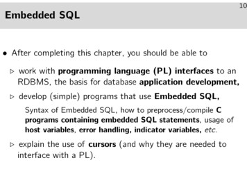
Categories of embedded systems4
Embedded system VS Generalpurpose systemEmbedded System VS General Purpose System The difference between an embedded system and a general purpose computersystem is one of purpose, and to a much lesser extent, design. While a general purpose system can be used for many things, an embeddedsystem is only meant for one purpose. General Purpose Systems The difference between an embedded system and ageneral purpose computer system is one of purpose, and to a much lesserextent, design. While a general purpose system can be used for many things, an embeddedsystem is only meant for one purpose. General Purpose Systems5
Embedded system VS Generalpurpose systemGeneral Purpose Systems A general purpose computer system is what you think of when someone saysthe word "computer.“ The defining feature of a general purpose computer is that it can bereconfigured for a new purpose. In the early days of digital computers, this involved actually rewiring the entiresystem. Today, most end users aren't even aware that this is happening, as the processhas become completely transparent.6
Embedded system VS Generalpurpose systemEmbedded Systems: An embedded system is a little harder to pin down. It is dedicated to a singlepurpose, or a small set of purposes. Embedded systems can be found in nearly every single piece of modern electronics-in fact, they are the electronics. A modern television, a portable music player, a computer-controlled air conditioningsystem or virtually anything made in the last 10 years that isn't a general purposesystem and requires electricity: that is what an embedded system is7
HISTORY OF AN EMBEDDED SYSTEMS Embedded systems date back to the 1960s. Charles Stark Draper developed an integrated circuit (IC) in 1961 to reduce the size andweight of the Apollo Guidance Computer, the digital system installed on the ApolloCommand Module and Lunar Module. The first computer to use ICs, it helped astronauts collect real-time flight data. In 1968, the first embedded system for a vehicle was released; the Volkswagen 1600used a microprocessor to control. I t 1987, the first embedded operating system, the real-time VxWorks, was released byWind River, followed by Microsoft's Windows Embedded CE in 1996. By the late 1990s, the first embedded Linux products began to appear. Today, Linux isused in almost all embedded devices.8
Classification of embedded systemEmbedded systems can be classified into three different types:small scale embedded systems, medium scale embedded systems, andsophisticated embedded systems.1) Small scale embedded systems: These usually use 8 bit or 16 bitmicrocontrollers, and have minimum hardware and software. They are so small andrequire little power they may be powered by a battery.2) Medium scale embedded systems: They use either one or a few 16 bit or 32 bitmicrocontrollers, and hardware and software is more complex as compared tosmall scale embedded systems.3) Sophisticated embedded systems: The most complex of the three classificationsmentioned.9
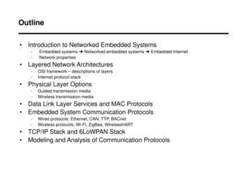
Major applications of Embedded systems10
Characteristics and Quality Attributes of Embedded Systems.Characteristics of embedded system: Application and Domain specific Reactive and Real time Operation in harsh environment Distributed Small size and weight Power concerns11
Characteristics and Quality Attributes of Embedded SystemsQUALITY ATTRIBUTES OF EMBEDDED SYSTEMThere are two types of quality attributes are:1. Operational Quality Attributes. Response 2.ThroughputReliabilityMaintainabilityScheduled or Periodic MaintenanceMaintenance to unexpected failureSecurity and SafetyNon-Operational Quality Attributes. Testability and Debug-ability Evolvability Portability Time to prototype and market Per unit and total cost12
UNIT-IITypical Embedded System13
General Purpose and Domain Specific Processors General purpose processors (GPP) are designed for general purposecomputers such as PCs or workstations. The computation speed of aGPP is the main concern and the cost of the GPP is usually muchhigher than tha of DSPs and microcontrollers. All techniques that canincrease CPU speed have been applied to GPPs. Generally a DSP processor has separate program and data memories.This allows the processor to fetch an instruction, while simultaneouslyfetching operands or storing results for a previous instruction. Often itis also possible to fetch multiple data from memory in one clock cycleby using multiple busses and multi port memories or multipleindependent data memories14
ASICsAn application-specific integrated circuit is an integrated circuit (IC) customized for aparticular use, rather than intended for general-purpose use. For example, a chipdesigned to run in a digital voice recorder or a high-efficiency bitcoin miner is anASIC. Application-specific standard products (ASSPs) are intermediate between ASICsand industry standard integrated circuits like the 7400 series or the 4000 series15
PLDsA programmable logic device is an electronic component used to buildreconfigurable digital circuits. Unlike integrated circuits which consist of logicgates and have a fixed function, a PLD has an undefined function at the time ofmanufacture16
Commercial Off-The-Shelf Components (COTS)Short for commercial off-the-shelf, an adjective that describessoftware or hardware products that are ready-made andavailable for sale to the general public. For example, MicrosoftOffice is a COTS product that is a packaged software solution forbusinesses17
Memory: ROMRead-only memory (ROM) is a type of non-volatile memory used in computers andother electronic devices. Data stored in ROM cannot be electronically modifiedafter the manufacture of the memory device. Read-only memory is useful forstoring software that is rarely changed during the life of the system, sometimesknown as firmware. Software applications for programmable devices can bedistributed as plug-in cartridges containing read-only memory.18
Memory:There are two main kinds of semiconductor memory Volatile Non volatile Examples of non-volatile memory are flash memory (used as secondarymemory) and ROM, PROM, EPROM and EEPROM memory (used forstoring firmware such as BIOS). Examples of volatile memory are primary storage, which is typically dynamicrandom-access memory (DRAM), and fast CPU cache memory, which istypically static random-access memory (SRAM) that is fast but energyconsuming,offering lower memory areal density than19
RAM Random-access memory is a form of computer memory that can be readand changed in any order, typically used to store working data and machinecode. A random-access memory device allows data items to be read orwritten in almost the same amount of time irrespective of the physicallocation of data inside the memory. RAM contains multiplexing and demultiplexing circuitry, to connect the datalines to the addressed storage for reading or writing the entry. Usually morethan one bit of storage is accessed by the same address, and RAM devicesoften have multiple data lines and are said to be "8-bit" or "16-bit", etc.devices.20
Memory according to the type of Interface,DSP processor data paths are optimized to provide extremely high performance oncertain kinds of arithmetic-intensive algorithms. However, a powerful data path is, atbest, only part of a high-performance processor. To keep the data path fed with dataand to store the results of data path operations, DSP processors require the ability tomove large amounts of data to and from memory quickly.DSP processor data paths are designed to perform a multiply-accumulate operation inone instruction cycle. This means that the arithmetic operations required for one tapcan be computed in one instruction cycle. However, to achieve this performance, theprocessor must be able to make several accesses to memory within one instructioncycle. Specifically, the processor must: fetch the multiply-accumulate instruction, read the appropriate data value from the delay line, read the appropriate coefficient value, and write the data value to the next location in the delay line to shift data through thedelay line.Thus, the processor must make four accesses to memory in one instruction cycle if themultiply-accumulate operation is to execute in a single instruction cycle. In practice,some processors use other techniques (as discussed later) to reduce the actual numberof memory accesses needed to three or even two. Nevertheless, all processors requiremultiple memory accesses within one instruction cycle. This level of memory bandwidthis needed for many important DSP algorithms.21
Memory ShadowingShadow memory is a technique used to track and store information on computermemory used by a program during its execution. Shadow memory consists ofshadow bytes that map to individual bits or one or more bytes in main memory.These shadow bytes are typically invisible to the original program and are usedto record information about the original piece of data.22
Memory selection for Embedded Systems Many types of memory devices are available for use inmodern computer systems. As an embedded software engineer, you must be awareof the differences between them and understand how touse each type effectively. The names of the memory types frequently reflect thehistorical nature of the development process and areoften more confusing than insightful.23
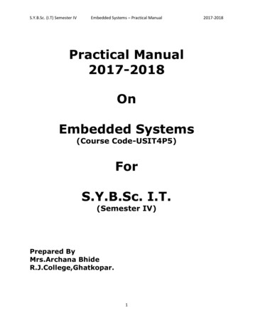
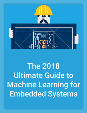
Sensors and Actuators A sensor is a device that changes a physical parameter to an electricaloutput. As against, an actuator is a device that converts an electrical signal toa physical output. . Sensor generates electrical signals whilean actuator results in the production of energy in the form of heat or motion Sensors and Actuators are essential elements of the embedded systems.These are used in several real-life applications such as flight control system inan aircraft, process control systems in nuclear reactors, power plants thatrequire to be operated on an automated control. Sensors and Actuatorsmainly differ by the purpose both provide, the sensor is used to monitor thechanges in the environment by using measurands while the actuator is usedwhen along with monitoring the control is also applied such as to control thephysical change24
Sensors and Actuators25
Sensors Sensor is transducer that converts physical stimulus from one form into a moreuseful form to measure stimulus.26
ACTUATORSActuators that convert the controller command signal into a change in a physicalparameter. the change is usually mechanical.(e.g.position or velocity.)27
Communication Interface: Onboard and ExternalCommunication Interfaces. Onboard communication Interface. The communication channel which interconnects thevarious components within an embedded product is referred as device/broad levelcommunication interface. The product level communication interface is responsible fordata transfer between the E.S and other devices or modules SoCs (System on a Chip) include external interfaces, typically for communicationprotocols. These are often based upon industry standards such as USB, FireWire,Ethernet, USART, SPI, HDMI, I²C, etc. These interfaces will differ according to theintended application. Wireless networking protocols such as Wi-Fi, Bluetooth, 6LoWPANand near-field communication may also be supported. When needed, SoCs include analog interfaces including analog-to-digital and digital-toanalog converters, often for signal processing. These may be able to interface withdifferent types of sensors or actuators, including smart transducers. They may interfacewith application-specific modules or shields Or they may be internal to the SoC, such as ifan analog sensor is built in to the SoC and its readings must be converted to digitalsignals for mathematical processing.28
UNIT-IIIEMBEDDED FIRMFARE29
Embedded firmware: Embedded firmware is the flash memory chip that storesspecialized software running in a chip in an embedded device to control itsfunctions. Firmware in embedded systems fills the same purpose as a ROM but can beupdated more easily for better adaptability to conditions or interconnecting withadditional equipment. For example, embedded software may run on ROM chips. Also, embeddedsoftware is often the only computer code running on a piece of hardware whilefirmware can also refer to the chip that houses a computer’s EFI or BIOS, whichhands over control to an OS that in turn launches and controls programs.30
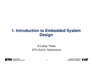
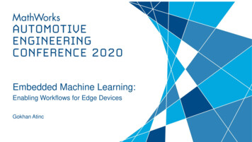
Reset circuit: The reset circuit is essential to ensure that the device is not operating at avoltage level where the device not guaranteed to operate. During systempower ON. The reset signal brings the internal registers and the differenthardware system of the processor/controller to a known state and starts thefirmware execution from the reset vector. The reset signal can be either active high (the processor undergoes resetwhen the reset pin of the processor is at logic high) or active low(the processorundergoes reset when the pin of the processor is at logic low).since theprocessor operation is synchronized to a clock signal, the reset pulse should bewide enough to give time for the clock oscillator to stabilize before the internalreset state starts. Some microprocessors/controllers contain built in internal reset circuitry andthey don’t require external reset circuitry. Figure illustrates a resistor capacitorbased passive reset circuit for active high and low configurations. The resetpulse width can be adjusted by changing the resistance value R andcapacitance value C.31
RC Based reset circuitFigure : RC based Reset circuit32
Brown-out Protection Circuit: Brown-out protection circuit prevents the processor/controller from unexpectedprogram execution behavior when the supply voltage to the processor/controllerfalls below a specified voltage. The processor behavior may not be predictable if the supply voltage falls belowthe recommended operating voltage. It may lead to situations like datacorruption. A brown-out protection circuit holds the processor/controller in reset state,when the operating voltage falls below the threshold, until it rises above thethreshold voltage.33
External Brown out protection circuit Certain processors/controllers support built in brown-out protection circuitwhich monitors the supply voltage internally If the processor/controller doesn’t integrate a built-in brown-out protectioncircuit, the same can be implemented using external passive circuits orsupervisor ICs The zener diode D and transistor Q forms the heart of the circuit. Thetransistor conducts always when the supply voltage VCC is greater than thatof the sum of VBE and VZ. The transistor stops conducting when the supply voltage falls below the sumof VBE and VZ. The values of the resistors can be selected based on theelectrical characteristics.34
Oscillator Unit: A microprocessor/microcontroller is a digital device made up of digital combinational andsequential circuits . The instruction execution of a microprocessor/controller occurs in sync with a clock signal. The oscillator unit of the embedded system is responsible for generating the precise clockfor the processor. Certain processor/controller chips may not contain a built-in oscillator unit and requirethe clock pulses to be generated and supplied externally.35
OSCILLATOR: Quartz crystal Oscillators are example for clock pulse generating devices. The total system power consumption is directly proportional to the clockfrequency. The power consumption increase with the increase in the clockfrequency . The accuracy of the program execution depends on the accuracy of the clocksignal. The accuracy of the clock frequency of the crystal oscillator isnormally expressed in terms of parts per million.36
Real Time Clock (RTC): The system component responsible for keeping track of time. RTC holdsinformation like current time (In hour, minutes and seconds) in 12 hour /24 hourformat, date, month, year, day of the week etc and supplies timing reference tothe system. RTC is intended to function even in the absence of power. RTCs are available inthe form of Integrated Circuits from different semiconductor manufacturers likeMaxim/Dallas, ST Microelectronics etc . The RTC chip contains a microchip for holding the time and date relatedinformation and backup battery cell for functioning in the absence of power, in asingle IC package. The RTC chip is interfaced to the processor or controller of the embeddedsystem. For Operating System based embedded devices. a timing reference is essentialfor synchronizing the operations of the OS kernel. The RTC can interrupt the OSkernel by asserting the interrupt line of the processor/controller to which the RTCinterrupt line is connected.37
Watch Dog Timer (WDT): A timer unit for monitoring the firmware execution. Depending on the internal implementation, the watchdog timer incrementsor decrements a free running counter with each clock pulse and generates areset signal to reset the processor if the count reaches zero for a down countingwatchdog, or the highest count value for an up counting watchdog. If the watchdog counter is in the enabled state, the firmware can write a zero(for up counting watchdog implementation) to it before starting the executionof a piece of code (subroutine or portion of code which is susceptible toexecution hang up) and the watchdog will start counting. If the firmwareexecution doesn’t complete due to malfunctioning, within the time required bythe watchdog to reach the maximum count, the counter will generate a resetpulse and this will reset the processor. If the firmware execution completes before the expiration of the watchdogtimer the WDT can be stopped from action.38
WATCH DOG TIMER Most of the processors implement watchdog as a built-in component and providesstatus register to control the watchdog timer (like enabling and disabling watchdogfunctioning) and watchdog timer register for writing the count value. If theprocessor/controller doesn’t contain a built in watchdog timer, the same can beimplemented using an external watchdog timer IC circuit.39
Embedded Firmware Design & Development languages: The embedded firmware is responsible for controlling the various peripherals ofthe embedded hardware and generating response in accordance with thefunctional requirements of the product. The embedded firmware is the master brain of the embedded system. The embedded firmware imparts intelligence to an Embedded system. It is a one time process and it can happen at any stage. There exist two basic approaches for the design and implementation ofembedded firmware, namely. The Super loop based approach The Embedded Operating System based approach40
Embedded firmware Design Approaches The decision on which approach needs to be adopted for firmwaredevelopment is purely dependent on the complexity and system requirements.1.Embedded firmware Design Approaches – The Super loop: The Super loop based firmware development approach is Suitable forapplications that are not time critical and where the response time is not soimportant (Embedded systems where missing deadlines are acceptable). It is very similar to a conventional procedural programming where the code isexecuted task by task The tasks are executed in a never ending loop.41
Pros and Cons:Pros: Doesn’t require an Operating System for task scheduling and monitoring andfree from OS related overheads Simple and straight forward design Reduced memory footprintCons: Non Real time in execution behavior (As the number of tasks increases thefrequency at which a task gets CPU time for execution also increases) Any issues in any task execution may affect the functioning of the product (Thiscan be effectively tackled by using Watch Dog Timers for task executionmonitoring)Enhancements: Combine Super loop based technique with interrupts Execute the tasks (likekeyboard handling) which require Real time attention as Interrupt Service routines.42
Embedded firmware Design Approaches – Embedded OSbased Approach:2.Embedded firmware Design Approaches – Embedded OS based Approach: The embedded device contains an Embedded Operating System which can be oneof: A Real Time Operating System (RTOS) A Customized General Purpose Operating System (GPOS) The Embedded OS is responsible for scheduling the execution of user tasks and theallocation of system resources among multiple tasks It Involves lot of OS related overheads apart from managing and executing userdefined tasks Microsoft Windows XP Embedded is an example of GPOS for embedded devices.43
Embedded firmware Development Languages/OptionsEmbedded firmware Development Languages/Options1.Assembly Language2.High Level Language Subset of C (Embedded C) Subset of C (Embedded C ) Any other high level language with supported Cross-compiler3.Mix of Assembly & High level Language Mixing High Level Language (Like C) with Assembly Code Mixing Assembly code with High Level Language (Like C) Inline Assembly44
Embedded firmware Development Languages/OptionsEmbedded firmware Development Languages/Options – Assembly Language ‘Assembly Language’ is the human readable notation of ‘machine language’ ‘Machine language’ is a processor understandable language Machine language is a binary representation and it consists of 1s and 0s Assembly language and machine languages are processor/controller dependent An Assembly language program written for one processor/controller family will notwork with others Assembly language programming is the process of writing processor specificmachine code in mnemonic form, converting the mnemonics into actual processorinstructions (machine language) and associated data using an assembler The general format of an assembly language instruction is an Op code followed byOperands The Op code tells the processor/controller what to do and the Operands provide thedata and information required to perform the action specified by the op code It is not necessary that all op code should have Operands following them. Some ofthe Op code implicitly contains the operand and in such situation no operand isrequired. The operand may be a single operand, dual operand or more45
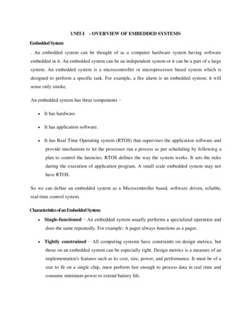
2.Assembly Language – Source File to Hex FileTranslation:2.Assembly Language – Source File to Hex File Translation: The Assembly language program written in assembly code is saved as .asm (Assemblyfile) file or a .src (source) file or a format supported by the assembler The software utility called ‘Assembler’ performs the translation of assembly code tomachine code The assemblers for different family of target machines are different. A51 MacroAssembler from Keil software is a popular assembler for the 8051 family micro c ontroller.Figure : Assembly Language to machine languageconversion process46
Advantages:1 .Efficient Code Memory & Data Memory Usage (Memory Optimization): The developer is well aware of the target processor architecture and memoryorganization, so optimized code can be written for performing operations. This leads to less utilization of code memory and efficient utilization of datamemory.2. High Performance: Optimized code not only improves the code memory usage but also improves thetotal system performance. Through effective assembly coding, optimum performance can be achieved fortarget processor.3.Low level Hardware Access: Most of the code for low level programming like accessing external device specificregisters from OS kernel ,device drivers, and low level interrupt routines, etc aremaking use of direct assembly coding.4.Code Reverse Engineering: It is the process of understanding the technology behind a product by extractingthe information from the finished product. It can easily be converted into assembly code using a dis-assembler program forthe target machine.47
Drawbacks:1. High Development time: The developer takes lot of time to study about architecture , memoryorganization, addressing modes and instruction set of targetprocessor/controller. More lines of assembly code is required for performing a simple action.2. Developer dependency: There is no common written rule for developing assembly language basedapplications.3. Non portable: Target applications written in assembly instructions are valid only for thatparticular family of processors and cannot be re-used for another targetprocessors/controllers. If the target processor/controller changes, a complete re-writing of theapplication using assembly language for new target processor/controller isrequired.48
Embedded firmware Development Languages/Options. Embedded firmware Development Languages/Options – High Level Language The embedded firmware is written in any high level language like C, C A software utility called ‘cross-compiler’ converts the high level language to targetprocessor specific machine code The cross-compilation of each module generates a corresponding object file. The objectfile does not contain the absolute address of where the generated code needs to beplaced (a re-locatable code) on the program memory The software program called linker/locater is responsible for assigning absolute addressto object files during the linking process The Absolute object file created from the object files corresponding to different sourcecode modules contain information about the address where each instruction needs to beplaced in code memory A software utility called ‘Object to Hex file converter’ translates the absolute object fileto corresponding hex file (binary file)49
Advantages:Reduced Development time: Developer requires less or little knowledge on internal hardware details andarchitecture of the target processor/Controller.Developer independency: The syntax used by most of the high level languages are universal and a programwritten high level can easily understand by a second person knowing the syntax of thelanguagePortability: An Application written in high level language for particular target processor/controller can be easily be converted to another target processor/controller specificapplication with little or less effortDrawbacks: The cross compilers may not be efficient in generating the optimized target processorspecific instructions Target images created by such compilers may be messy and non optimized in terms ofperformance as well as code size The investment required for high level language based development tools (IDE) is highcompared to Assembly Language based firmware development tools.50
Mixing High level language like ‘C’ with Assembly Language2. Mixing High level language like ‘C’ with Assembly Language (‘C’ with AssemblyLanguage) The source code is already available in assembly language and routine written in a highlevel language needs to be included to the existing code. The entire source code is planned in Assembly code for various reasons like optimizedcode, optimal performance, efficient code memory utilization and proven expertise inhandling the assembly. The functions written in ‘C’ use parameter passing to the function and returns values tothe calling functions.3. In line Assembly: Inline assembly is another technique for inserting the target processor/controller specificassembly instructions at any location of source code written in high level language ‘C’ Inline Assembly avoids the delay in calling an assembly routine from a ‘C’ code. Special keywords are used to indicate the start and end of Assembly instructions.51
UNIT-IVRTOS BASED EMBEDDED SYSTEM DESIGN52
Operating System BasicsAn Operating system (OS) is a piece of software that controlsthe overall operation of the Computer. It acts as an interfacebetween hardware and application programs .It facilitates theuser to format disks, create, print, copy, delete and display files,read data from files ,write data to files , control the I/Ooperations, allocate memory locations and process theinterrupts etc.53
Operating System Basics.It provides the users an interface to the hardwareresources. In a multiuser system it allows several users toshare the CPU time, share the other system resourcesand provide inter task communication, Timers, clocks,memory management and also avoids the interference ofdifferent users in sharing the resources etc. Hence the OSis also known as a resource manager.54
Types of operating systemsAn Operating system (OS) is nothing but a piece of software that controlsthe overall operation of the Computer. It acts as an interface betweenhardware and application programs .It facilitates the user to format disks,create ,print ,copy , delete and display files , read data from files ,writedata to files ,control the I/O operations , allocate memory locations andprocess the interrupts etc. It provides the users an interface to thehardware resources.55
Types of operating systems.I
Classification of embedded system 9 Embedded systems can be classified into three different types: small scale embedded systems, medium scale embedded systems, and sophisticated embedded systems. 1) Small scale embedded systems: These usually use 8 bit or 16 bit microcontrollers, and