Transcription
Outline Introduction to Networked Embedded Systems- Layered Network Architectures- Guided transmission mediaWireless transmission mediaData Link Layer Services and MAC ProtocolsEmbedded System Communication Protocols- OSI framework – descriptions of layersInternet protocol stackPhysical Layer Options- Embedded systems Networked embedded systems Embedded InternetNetwork propertiesWired protocols: Ethernet, CAN, TTP, BACnetWireless protocols: Wi-Fi, ZigBee, WirelessHARTTCP/IP Stack and 6LoWPAN StackModeling and Analysis of Communication Protocols
NETWORKS FOR ALL SIZES AND SCALES NoCs – connecting processors inside MPSoCs SPI, I2C, UART. – connecting discrete components inside boards USB, FireWire. – connecting peripherals around a PC Bluetooth, RFID, NFC. – connecting peripherals or sensors in small areas (BANs,PANs .) CAN, fieldbuses. – connecting sensors, actuators and controlling equipment in amonitoring or control system (DCS) Zigbee, WirelessHART. – connection of self-organized wireless sensors (WSNs) Ethernet, WiFi. – connection of PCs and equipment in local areas (LANs) 10G Ethernet, ATM. – connection of large systems in large areas (MANs, WANs) GSM, LTE, WiMax – wide area communications (MANs,WANs)
WHY NETWORKED AND DISTRIBUTED ARCHITECTURE Processing closer to data source / sink- Dependability- System composition by integrating components and subsystemsScalability- Error-containment within nodesComposability- Intelligent sensors and actuatorsReduce the computational overhead on the central processing nodeEasy addition of new nodes with new or replicated functionalityEspecially for wirelessMaintainability-Modularity and easy node replacementSimplification of the cabling, especially for wireless
DISTRIBUTED VS. NETWORKED EMBEDDED SYSTEMSDistributed Embedded Systems System-centered (designed as a whole)- Confined in space (despite possibly large)Normally fixed set of componentsPreference for wired networks w/ fixed topologyMost common non-functional requirements-Real-time--Dependability--End-to-end constraints on response to stimuliJitter constraints on periodic activitiesUltra high reliability and safety, high availabilityComposabilityMaintainability
DISTRIBUTED VS. NETWORKED EMBEDDED SYSTEMSNetworked Embedded Systems Interconnected stand-alone equipment or systems for extra functionality(communication-centered)-Fuzzy notion of global systemVariable set of componentsA combination of wireless/wired networks- Structured / Ad-hoc connectionsVarying topologyMulti-hop communicationMost common non-functional ation(Soft) real-time
NETWORK PROPERTIES Supported topologies- star, line, tree, mesh, bus, ring Media access mechanisms- controlled access vs. uncontrolled access Network performance metrics- Bandwidth, throughput and goodput Network real-time performance- latency, jitter, coherent notion of time Network Security-Cryptosecurity, Emission, Transmission and Physical security
Outline Introduction to Networked Embedded Systems- Layered Network Architectures- Guided transmission mediaWireless transmission mediaData Link Layer Services and MAC ProtocolsEmbedded System Communication Protocols- OSI framework – descriptions of layersInternet protocol stackPhysical Layer Options- Embedded systems Networked embedded systems Embedded InternetNetwork propertiesWired protocols: Ethernet, CAN, TTP, BACnetWireless protocols: Wi-Fi, ZigBee, WirelessHARTTCP/IP Stack and 6LoWPAN StackModeling and Analysis of Communication Protocols
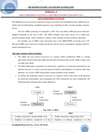
LAYER ARCHITECTURE Layer architecture simplifies the network design.-Explicit structure allows identification, relationship of complex system’s pieces.-Modularization eases maintenance, updating of system.-Change of implementation of layer’s service transparent to rest of system. It is easy to debug network applications with a layered architecture. The network management is easier due to the layered architecture. Network layers follow a set of rules, called protocol. The protocol defines the format of the data being exchanged, and thecontrol and timing for the handshake between layers.
WHY LAYERING CONSIDERED HARMFUL? Structured layering implies that the functions of each layer are carriedout completely before the protocol data unit is passed to the next layer. This means that the optimization of each layer has to be doneseparately. Such ordering constraints are in conflict with efficient implementation ofdata manipulation functions.
ISO/OSI REFERENCE MODEL Application: Network processes to applications- Presentation: Data representation- IP, routing protocolsLink: Access to media- TCP, UDPNetwork: Addressing and routing- synchronization, checkpointing, recovery of data exchangeTransport: End-to-end connections- encryption, compression, machine-specific conventionsSession: Interhost communication- FTP, SMTP, HTTP Ethernet, 802.111 (WiFi), PPPPhysical: bits “on the orklinkphysical
INTERNET PROTOCOL STACK Internet stack “missing” presentation and session layers.- Application: supporting network applications- IP, routing protocolsLink: data transfer between neighboring networkelements- TCP, UDPNetwork: routing of datagrams from source to destination- FTP, SMTP, HTTPTransport: process data transfer- These services, if needed, must be implemented in et, 802.111 (WiFi), PPPPhysical: bits “on the wire”physical
EMBEDDED / REAL-TIME PROTOCOL STACK The OSI 7 layers impose a considerable overhead-Time to execute the protocol stackTime to transmit protocol control informationMemory requirements (for all intermediate protocol invocations) Many embedded / real-time networks-are dedicated to a well defined applicationuse single broadcast domain (no need for routing)use short messages (no need to fragment/reassemble)Figure from Dr. Luis Almeida
Outline Introduction to Networked Embedded Systems- Layered Network Architectures- Guided transmission mediaWireless transmission mediaData Link Layer Services and MAC ProtocolsEmbedded System Communication Protocols- OSI framework – descriptions of layersInternet protocol stackPhysical Layer Options- Embedded systems Networked embedded systems Embedded InternetNetwork propertiesWired protocols: Ethernet, CAN, TTP, BACnetWireless protocols: Wi-Fi, ZigBee, WirelessHARTTCP/IP Stack and 6LoWPAN StackModeling and Analysis of Communication Protocols
GUIDED TRANSMISSION MEDIAMagnetic Media HP Ultrium tape 100GB. A box 60x60x60 holds 2000 tapes 200 Terabytes 1600 Tbits. A box can be delivered in 24 hours anywhere in USA throughput: 1600Tbits/86400 sec 19 Gbps!Twisted Pair/ Unshielded TP (UTP) Classic telephone lines-Category 3 (a) – 16MHzCategory 5 (b) – 100 MHzCategory 6 – 250 MHzCategory 7 – 600 MHz Throughput : a few Mbit/sec – Gbits/sec. Works up to 100m, afterwards repeaters needed.
GUIDED TRANSMISSION MEDIA (CONT.)Coaxial Cable Bandwidth 1 GHz (better shielding) Up to 200mFiber Optics Rather used at higher bandwidths Invulnerable to electric andelectromagnetic signals Could be very long Hard to tamper with - Security Usually simplex transmission
THE ELECTROMAGNETIC SPECTRUMoptical transmission1 Mm300 Hz10 km30 kHzVLFLF100 m3 MHzMFHFVLF Very Low FrequencyLF Low FrequencyMF Medium FrequencyHF High FrequencyVHF Very High Frequency1m300 MHzVHF10 mm30 GHzUHFSHFEHF100 m3 THzinfrared1 m300 THzvisible light UVUHF Ultra High FrequencySHF Super High FrequencyEHF Extra High FrequencyUV Ultraviolet Light Frequency and wave length: c/f , wave length , speed of light c 3x10⁸m/s,frequency f Radio spectrum is part of the electromagnetic spectrum from 1Hz to 3THz:http://en.wikipedia.org/wiki/Radio spectrum
DATA LINK LAYER SERVICES Framing, link access:- Reliable delivery between adjacent nodes- Pacing between adjacent sending and receiving nodesError detection:-Errors caused by signal attenuation, noise.-Receiver detects presence of errors: signals sender for retransmission or drops frameError correction:- Seldom used on low bit-error link (fiber, some twisted pair)wireless links: high error ratesFlow control:- encapsulate datagram into frame, adding header, tailerchannel access if shared medium“MAC” addresses used in frame headers to identify source, destinationReceiver identifies and corrects bit error(s) without resorting to retransmissionHalf-duplex and full-duplex-with half duplex, nodes at both ends of link can transmit, but not at same time
MULTIPLE ACCESS PROTOCOLS Single shared broadcast channel Two or more simultaneous transmissions by nodes: interference-Collision if node receives two or more signals at the same timeMultiple Access Protocol distributed algorithm that determines how nodes share channel, i.e.,determine when node can transmit. communication about channel sharing must use channel itself.-no out-of-band channel for coordination
AN IDEAL MULTIPLE ACCESS PROTOCOLgiven: broadcast channel of rate R bpsdesiderata:1. when one node wants to transmit, it can send at rate R.2. when M nodes want to transmit, each can send at average rateR/M3. fully decentralized: no special node to coordinate transmissions no synchronization of clocks, slots4. simple
MAC PROTOCOLS: TAXONOMYThree broad classes: Channel partitioning-divide channel into smaller “pieces” (time slots, frequency, code)-allocate piece to node for exclusive useRandom access-channel not divided, allow collisions-“recover” from collisions“Taking turns”-nodes take turns, but nodes with more to send can take longer turns
RANDOM ACCESS PROTOCOLS When node has packet to send:-Transmit at full channel data rate R.-No a priori coordination among nodes-Two or more transmitting nodes “collision”Random access MAC protocol specifies:-How to detect collisions-How to recover from collisions (e.g., via delayed retransmissions)Examples of random access MAC protocols:-Slotted ALOHA-ALOHA-CSMA, CSMA/CD, CSMA/CA
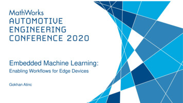
SLOTTED ALOHAnode 111node 222node 33C1123ECSE3CESSPros:Cons: Collisions, wasting slots Idle slots Nodes may be able to detectcollision in less than time totransmit packet Clock synchronizationSingle active node cancontinuously transmit at full rateof channel Highly decentralized: only slots innodes need to be in sync Simple
SLOTTED ALOHA: EFFICIENCYefficiency: long-runfraction of successful slots(many nodes, all with manyframes to send) suppose: N nodes with manyframes to send, each transmitsin slot with probability p prob that given node hassuccess in a slot p(1-p)N-1 prob that any node has asuccess Np(1-p)N-1 max efficiency: find p* thatmaximizesNp(1-p)N-1 for many nodes, take limit ofNp*(1-p*)N-1 as N goes toinfinity, gives:max efficiency 1/e .37at best: channelused for usefultransmissions 37%of time!
PURE (UNSLOTTED) ALOHA Unslotted Aloha: simpler, no synchronization When frame first arrives:- transmit immediatelyCollision probability increases:-frame sent at t0 collides with other frames sent in [t0-1,t0 1]
PURE ALOHA EFFICIENCYP(success by given node) P(node transmits) .P(no other node transmits in [t0-1,t0] .P(no other node transmits in [t0,t0 1] p . (1-p)N-1 . (1-p)N-1 p . (1-p)2(N-1) choosing optimum p and then letting n 1/(2e) .18even worse than slotted Aloha!
CSMA (CARRIER SENSE MULTIPLE ACCESS)CSMA: listen before transmit If channel sensed idle: transmit entire frame If channel sensed busy: defer transmission Human analogy: don’t interrupt others!
CSMA/CD (COLLISION DETECTION)CSMA/CD: carrier sensing, deferral as in CSMA collisions detected within short time colliding transmissions aborted, reducing channel wastageCollision detection:-easy in wired media: measure signal strengths, compare transmitted,received signals-difficult in wireless media: received signal strength overwhelmed by localtransmission strengthHuman analogy: the polite conversationalist
CSMA/CA (COLLISION AVOIDANCE) CSMA/CA:-Wireless MAC protocols often use collision avoidance techniques, in conjunction with a(physical or virtual) carrier sense mechanism-To be discussed more in WiFi and ZigBee protocolsCollision avoidance-Nodes hearing RTS or CTS stay silent for the duration of the correspondingtransmission.-Once channel becomes idle, the node waits for a randomly chosen duration beforeattempting to transmit.Carrier sense-Nodes stay silent when carrier sensed (physical/virtual)-Physical carrier sense: carrier sense threshold-Virtual carrier sense using Network Allocation Vector (NAV): NAV is updated based onoverheard RTS/CTS/DATA/ACK packets
“TAKING TURNS” MAC PROTOCOLSChannel partitioning MAC protocols: Share channel efficiently and fairly at high load Inefficient at low load: delay in channel access, 1/N bandwidthallocated even if only 1 active node!Random access MAC protocols Efficient at low load: single node can fully utilize channel High load: collision overhead“taking turns” protocols Look for best of both worlds.
SUMMARY OF MAC PROTOCOLS Channel partitioning, by time, frequency or code- Time Division, Frequency DivisionRandom access (dynamic)-ALOHA, S-ALOHA, CSMA, CSMA/CD-Carrier sensing: easy in some technologies (wire), hard in others(wireless)-CSMA/CD used in Ethernet-CSMA/CA used in 802.11Taking turns-Polling from central site, token passing-Bluetooth, FDDI, token ring
Outline Introduction to Networked Embedded Systems- Layered Network Architectures- Guided transmission mediaWireless transmission mediaData Link Layer Services and MAC ProtocolsEmbedded System Communication Protocols- OSI framework – descriptions of layersInternet protocol stackPhysical Layer Options- Embedded systems Networked embedded systems Embedded InternetNetwork propertiesWired protocols: Ethernet, CAN, TTP, BACnetWireless protocols: Wi-Fi, ZigBee, WirelessHARTTCP/IP Stack and 6LoWPAN StackModeling and Analysis of Communication Protocols
EMBEDDED SYSTEM COMMUNICATION PROTOCOLSWired communication protocol examples: Ethernet (802.3) CAN TTP BACnetWireless communication protocol examples: Wi-Fi (802.11) ZigBee (based on 802.15.4 PHY and MAC) WirelessHART (Not discussed in this lecture)
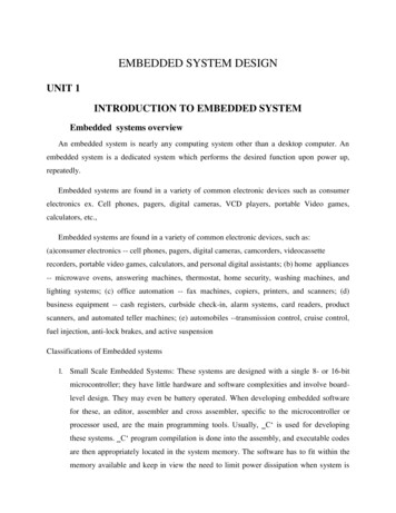
INFRASTRUCTURE VS. AD-HOC NETWORKSinfrastructurenetworkAPAPad-hoc networkwired networkAP: Access PointAP
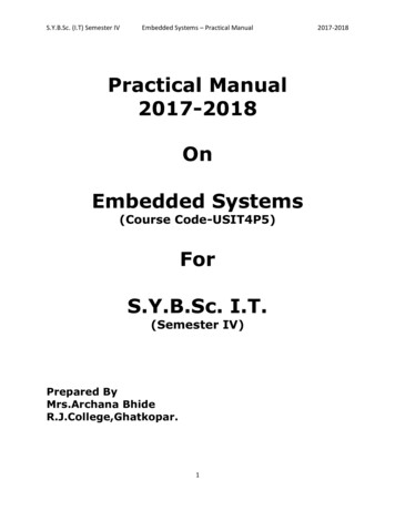
802.11: INFRASTRUCTURE802.11 LANSTA1802.x LANBSS1PortalAccessPoint Station (STA)-terminal with access mechanisms tothe wireless medium and radio contactto the access point Access Point-station integrated into the wirelessLAN and the distribution system Basic Service Set (BSS)-group of stations using the same AP Portal-bridge to other (wired) networks Distribution System-interconnection network to form onelogical network (EES: ExtendedService Set) based on several BSSDistribution SystemAccessPointESSBSS2STA2802.11 LANSTA3
802.11: AD HOC MODE802.11 LANDirect communication within alimited rangeSTA1STA3IBSS1STA2IBSS2STA5STA4802.11 LAN Station (STA): terminal withaccess mechanisms to thewireless medium Independent Basic Service Set(IBSS): group of stations usingthe same network
WLAN: IEEE 802.11B Data rate-1, 2, 5.5, 11 Mbit/s, depending onSNR-User data rate max. approx. 6Mbit/sQuality of Service- Best effort, no guarantees (unlesspolling is used, limited support inproducts)ProsTransmission range-Many installed systems and vendors-300m outdoor, 30m indoor-Available worldwide-Max. data rate 10m indoor-Free ISM-bandFrequency- Free 2.4 GHz ISM-bandAvailability-Many products and vendors Cons-Heavy interference on ISM-band-No service guarantees-Relatively low data rate
WLAN: IEEE 802.11A Data rate-- 6, 9, 12, 18, 24, 36, 48, 54 Mbit/s,depending on SNRUser throughput (1500 bytepackets): 5.3 (6), 18 (24), 24 (36),32 (54)6, 12, 24 Mbit/s mandatory Availability- Quality of Service- Some products, some vendorsBest effort, no guarantees (sameas all 802.11 products)ProsTransmission range-Fits into 802.x standards-100m outdoor, 10m indoor-Free ISM-band-E.g., 54 Mbit/s up to 5 m, 48 up to 12m, 36 up to 25 m, 24 up to 30m, 18 upto 40 m, 12 up to 60 m-Available, simple system-Uses less crowded 5 GHz band-Higher data ratesFrequency-Free 5.15-5.25, 5.25-5.35, 5.7255.825 GHz ISM-band Cons-Shorter range
WLAN: IEEE 802.11N Data rate-7.2, 14.4, 21.7, 28.9, , 72.2Mbit/s, depending on SNR Multiple input multiple output(MIMO) 20MHz and 40MHz bands Transmission range- - Increase range by several factorsdue to MIMOFrequency-Free 2.4GHz ISM-band-Free 5.15-5.25, 5.25-5.35, 5.7255.825 GHz ISM-bandAvailability-Some products, some vendorsQuality of Service Best effort, no guarantees (sameas all 802.11 products)Pros-Fits into 802.x standards-Free ISM-band-Available, simple system-Uses dual band-Higher data ratesCons-Interference on ISM-band
802.11 MAC LAYERDistributed and centralized access methods DCF CSMA/CA (mandatory) Collision avoidance via randomized “back-off“ mechanism Minimum distance between consecutive packets ACK packet for acknowledgements (not for broadcasts)DCF w/ RTS/CTS (optional) Distributed Foundation Wireless MAC Avoids hidden terminal problemPCF (optional) Access point polls terminals according to a list
DCF ILLUSTRATIONInterframe space (IFS)SenderReceiverTime Before a node transmits, it listens for activity on the network If medium is busy, node waits to transmit After medium is clear, don't immediately start transmitting. Otherwise all nodes would start talking at the same time! Instead, delay a random amount of time (random backoff)
802.11 - MAC LAYER (CONT.)Priorities defined through different inter frame spaces No guarantee, hard priorities SIFS (Short Inter Frame Spacing) PIFS (PCF IFS) Highest priority, for ACK, CTS, polling responseMedium priority, for time-bounded service using PCFDIFS (DCF, Distributed Coordination Function IFS) Lowest priority, for asynchronous data serviceDIFSmedium busyDIFSPIFSSIFScontentionnext framet
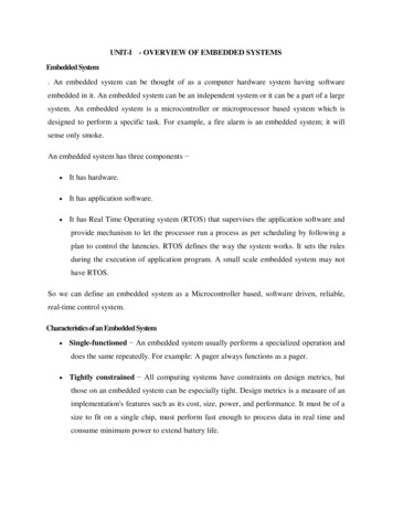
HIDDEN TERMINAL PROBLEMAB B can communicate with both A and C A and C cannot hear each other Problem C When A transmits to B, C cannot detect the transmission using the carriersense mechanism If C transmits, collision will occur at node BSolution Hidden sender C needs to defer
SOLUTION FOR HIDDEN TERMINAL PROBLEM: MACAABC When A wants to send a packet to B, A first sends a Request-to-Send(RTS) to B On receiving RTS, B responds by sending Clear-to-Send (CTS),provided that A is able to receive the packet When C overhears a CTS, it keeps quiet for the duration of the transfer-Transfer duration is included in both RTS and CTS
BACKOFF INTERVAL Collision avoidance- When transmitting a packet, choose a backoff interval in the range [0, CW]- CW is contention windowCount down the backoff interval when medium is idle- Backoff intervals used to reduce collision probabilityCount-down is suspended if medium becomes busyTransmit when backoff interval reaches 0
BACKOFF INTERVAL The time spent counting down backoff intervals is a part of MACoverhead Important to choose CW appropriately -large CW large overhead-small CW may lead to many collisions (when two nodes count down to 0simultaneously)How to choose an appropriate CW?
802.11 - FRAME FORMAT Types- control frames, management frames, data framesSequence numbers- important against duplicated frames due to lost ACKsAddresses- Sender, receiver, BSS identifierMiscellaneous-sending time, checksum, frame control, databytes2266626Frame Duration/ Address Address Address Sequence taCRC1ProtocolTo From MorePower MoreType SubtypeRetryWEP OrderversionDS DS FragMgmt Data
802.15.4 ARCHITECTUREUpper LayersIEEE 802.15.4 ServiceSpecific Convergence SubLayer (SSCS)IEEE 802.2LLC, Type IIEEE 802.15.4 MACIEEE 802.15.4868/915 MHzPHYIEEE 802.15.42400 MHzPHY
DEVICE ADDRESSING Two or more devices communicating on the same physical channelconstitute a WPAN which includes at least one FFD (PANcoordinator). Each independent PAN will select a unique PAN identifier. All devices operating on a network shall have unique 64-bitextended address. This address can be used for directcommunication in the PAN. An associated device can use a 16-bit short address, which isallocated by the PAN coordinator when the device associates.
IEEE 802.15.4 SUPPORTED TOPOLOGIES MAC supports 2 topologies: star and peer-to-peer Star topology supports beacon and no-beacon structure-All communication done through PAN coordinator
PHYSICAL FREQUENCIES AND CHANNELS868MHz / 915MHzPHY2.4 GHzPHY2.4 GHzChannel 0Channels 1-10868.3 MHz902 MHzChannels 11-262 MHz928 MHz5 MHz2.4835 GHz
IEEE 802.15.4 MAC OVERVIEW Star networks: devices are associated with coordinators Forming a PAN, identified by a PAN identifierCoordinator Bookkeeping of devices, address assignment, generate beacons Talks to devices and peer coordinatorsBeacon-mode superframe structure GTS assigned to devices upon request
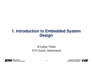
IEEE 802.15.4 GENERAL FRAME STRUCTUREPHY LayerMACLayerPayloadSynch. Header(SHR)MAC Header(MHR)PHY Header(PHR)Four Types of MAC Frames: Data Frame Beacon Frame Acknowledgment Frame MAC Command FrameMAC Service Data Unit(MSDU)MAC Protocol Data Unit (MPDU)PHY Service Data Unit (PSDU)MAC Footer(MFR)
EMBEDDED SYSTEM COMMUNICATION PROTOCOLSWired communication protocol examples: Ethernet (802.3) CAN TTP BACnetWireless communication protocol examples: Wi-Fi (802.11) ZigBee (based on 802.15.4 PHY and MAC) WirelessHART (Not discussed in this lecture)
EMBEDDED SYSTEM COMMUNICATION PROTOCOL: ETHERNET“dominant” wired LAN technology: cheap 20 for NIC first widely used LAN technology simpler, cheaper than token LANs andATM kept up with speed race: 10 Mbps – 10GbpsAn example avionics communication network:AFDX network (Avionics Full Duplex Ethernet(Figure from Airbus, more details can be foundat: /Slides/ARTIST2 IMA Itier.pdf)
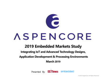
ETHERNET: PHYSICAL TOPOLOGY Bus: traditional topology-All workstations are connected on a single cable.-All transmissions go to all the connected workstation.Star: the most common solution today-Active switch in center-Each “spoke” runs a (separate) Ethernet protocolbus: coaxial cablestarTTEthernet
ETHERNET FRAME STRUCTURESending adapter encapsulates IP datagram (or other network layer protocolpacket) in Ethernet frametypedest.sourcepreamble address addressdata(payload)CRCPreamble: 7 bytes with pattern 10101010 followed by one byte with pattern10101011 Used to synchronize receiver, sender clock rates
ETHERNET: UNRELIABLE, CONNECTIONLESS Connectionless: no handshaking between sending and receiving NICs Unreliable: receiving NIC doesn’t send ACKs or NACKs to sendingNIC- data in dropped frames recovered only if initial sender uses higher layerreliable data transfer (e.g., TCP), otherwise dropped data lostEthernet’s MAC protocol: unslotted CSMA/CD with binary backoff
802.3 ETHERNET STANDARDS: LINK & PHYSICAL LAYERSMany different Ethernet standards Common MAC protocol and frame format Different speeds: 2 Mbps, 10 Mbps, 100 Mbps, 1Gbps, 10G bps Different physical layer media: fiber, cableapplicationtransportnetworklinkphysicalMAC protocoland frame ASE-SX100BASE-BXcopper (twisterpair) physical layerhttps://en.wikipedia.org/wiki/Ethernet physical layerfiber physical layer
- Embedded systems Networked embedded systems Embedded Internet - Network properties Layered Network Architectures - OSI framework – descriptions of layers - Internet protocol stack Physical Layer Options