Transcription
UNIT-I - OVERVIEW OF EMBEDDED SYSTEMSEmbedded System. An embedded system can be thought of as a computer hardware system having softwareembedded in it. An embedded system can be an independent system or it can be a part of a largesystem. An embedded system is a microcontroller or microprocessor based system which isdesigned to perform a specific task. For example, a fire alarm is an embedded system; it willsense only smoke.An embedded system has three components It has hardware. It has application software. It has Real Time Operating system (RTOS) that supervises the application software andprovide mechanism to let the processor run a process as per scheduling by following aplan to control the latencies. RTOS defines the way the system works. It sets the rulesduring the execution of application program. A small scale embedded system may nothave RTOS.So we can define an embedded system as a Microcontroller based, software driven, reliable,real-time control system.Characteristics of an Embedded System Single-functioned An embedded system usually performs a specialized operation anddoes the same repeatedly. For example: A pager always functions as a pager. Tightly constrained All computing systems have constraints on design metrics, butthose on an embedded system can be especially tight. Design metrics is a measure of animplementation's features such as its cost, size, power, and performance. It must be of asize to fit on a single chip, must perform fast enough to process data in real time andconsume minimum power to extend battery life.
Reactive and Real time Many embedded systems must continually react to changes inthe system's environment and must compute certain results in real time without anydelay. Consider an example of a car cruise controller; it continually monitors and reactsto speed and brake sensors. It must compute acceleration or de-accelerations repeatedlywithin a limited time; a delayed computation can result in failure to control of the car. Microprocessors based It must be microprocessor or microcontroller based. Memory It must have a memory, as its software usually embeds in ROM. It does notneed any secondary memories in the computer. Connected It must have connected peripherals to connect input and output devices. HW-SW systems Software is used for more features and flexibility. Hardware is usedfor performance and security.Advantages Easily Customizable Low power consumption Low cost Enhanced performance
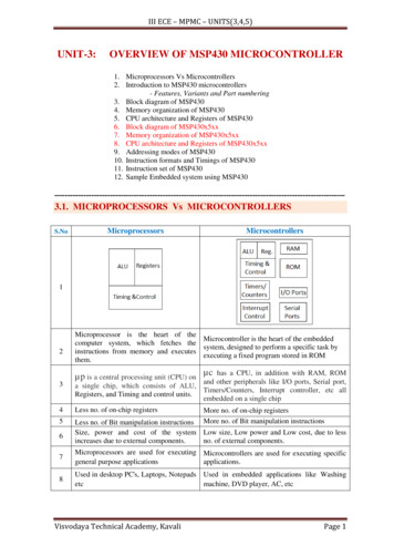
Disadvantages High development effort Larger time to marketBasic Structure of an Embedded SystemThe following illustration shows the basic structure of an embedded system Sensor It measures the physical quantity and converts it to an electrical signal whichcan be read by an observer or by any electronic instrument like an A2D converter. Asensor stores the measured quantity to the memory. A-D Converter An analog-to-digital converter converts the analog signal sent by thesensor into a digital signal. Processor & ASICs Processors process the data to measure the output and store it tothe memory. D-A Converter A digital-to-analog converter converts the digital data fed by theprocessor to analog data Actuator An actuator compares the output given by the D-A Converter to the actual(expected) output stored in it and stores the approved output.
Processor is the heart of an embedded system. It is the basic unit that takes inputs and producesan output after processing the data. For an embedded system designer, it is necessary to have theknowledge of both microprocessors and microcontrollers.Processors in a SystemA processor has two essential units Program Flow Control Unit (CU) Execution Unit (EU)The CU includes a fetch unit for fetching instructions from the memory. The EU has circuitsthat implement the instructions pertaining to data transfer operation and data conversion fromone form to another.The EU includes the Arithmetic and Logical Unit (ALU) and also the circuits that executeinstructions for a program control task such as interrupt, or jump to another set of instructions.A processor runs the cycles of fetch and executes the instructions in the same sequence as theyare fetched from memory.Types of ProcessorsProcessors can be of the following categories General Purpose Processor (GPP)oMicroprocessoroMicrocontrolleroEmbedded ProcessoroDigital Signal ProcessoroMedia Processor Application Specific System Processor (ASSP) Application Specific Instruction Processors (ASIPs)
.The Embedded system hardware includes elements like user interface, Input/Output interfaces,display and memory, etc.Generally, an embedded system comprises power supply, processor,memory, timers, serial communication ports and system application specific circuits.Types of Embedded SystemsEmbedded systems can be classified into different types based on performance, functionalrequirements and performance of the microcontroller.Types of Embedded systemsEmbedded systems are classified into four categories based on their performance and functionalrequirements: Stand alone embedded systems Real time embedded systems
Networked embedded systems Mobile embedded systemsEmbedded Systems are classified into three types based on the performance ofthe microcontroller such as Small scale embedded systems Medium scale embedded systems Sophisticated embedded systemsStand Alone Embedded SystemsStand alone embedded systems do not require a host system like a computer, it works by itself. Ittakes the input from the input ports either analog or digital and processes, calculates and convertsthe data and gives the resulting data through the connected device-Which either controls, drivesand displays the connected devices. Examples for the stand alone embedded systems are mp3players, digital cameras, video game consoles, microwave ovens and temperature measurementsystems.Real Time Embedded SystemsA real time embedded system is defined as, a system which gives a required o/p in a particulartime.These types of embedded systems follow the time deadlines for completion of a task. Realtime embedded systems are classified into two types such as soft and hard real time systems.Networked Embedded SystemsThese types of embedded systems are related to a network to access the resources. The connectednetwork can be LAN, WAN or the internet. The connection can be any wired or wireless. Thistype of embedded system is the fastest growing area in embedded system applications. Theembedded web server is a type of system wherein all embedded devices are connected to a webserver and accessed and controlled by a web browser. Example for the LAN networkedembedded system is a home security system wherein all sensors are connected and run on theprotocol TCP/IP
Mobile Embedded SystemsMobile embedded systems are used in portable embedded devices like cell phones, mobiles,digital cameras, mp3 players and personal digital assistants, etc.The basic limitation of thesedevices is the other resources and limitation of memory.Small Scale Embedded SystemsThese types of embedded systems are designed with a single 8 or 16-bit microcontroller, thatmay even be activated by a battery. For developing embedded software for small scale embeddedsystems, the main programming tools are an editor, assembler, cross assembler and integrateddevelopment environment (IDE).Medium Scale Embedded SystemsThese types of embedded systems design with a single or 16 or 32 bit microcontroller, RISCs orDSPs. These types of embedded systems have both hardware and software complexities. Fordeveloping embedded software for medium scale embedded systems, the main programmingtools are C, C , JAVA, Visual C , RTOS, debugger, source code engineering tool, simulatorand IDE.Sophisticated Embedded SystemsThese types of embedded systems have enormous hardware and software complexities, that mayneed ASIPs, IPs, PLAs, scalable or configurable processors. They are used for cutting-edgeapplications that need hardware and software Co-design and components which have toassemble in the final system.Applications of Embedded Systems:Embedded systems are used in different applications like automobiles, telecommunications,smart cards, missiles, satellites, computer networking and digital consumer electronics.
Embedded System InitializationIt takes just minutes for a developer to compile and run a Hello World! application on a nonembedded system. On the other hand, for an embedded developer, the task is not so trivial. Itmight take days before seeing a successful result. This process can be a frustrating experience fora developer new to embedded system development.Booting the target system, whether a third-party evaluation board or a custom design, can be amystery to many newcomers. Indeed, it is daunting to pick up a programmer s reference manualfor the target board and pore over tables of memory addresses and registers or to review thehardware component interconnection diagrams, wondering what it all means, what to do with theinformation (some of which makes little sense), and how to relate the information to running animage on the target system.Questions to resolve at this stage are how to load the image onto the target system, where in memory to load the image, how to initiate program execution, and how the program produces recognizable output.
We answer these questions in this chapter and hopefully reduce frustration by demystifying thebooting and initialization process of embedded systems.Serial CommunicationSerial TransferIn Telecommunication and Computer Science, serial communication is the process ofsending/receiving data in one bit at a time. It is like you are firing bullets from a machine gun toa target that’s one bullet at a time! ;)Parallel CommunicationParallel TransferParallel communication is the process of sending/receiving multiple data bits at a time throughparallel channels. It is like you are firing using a shotgun to a target – where multiple bullets arefired from the same gun at a time! ;)
Serial vs Parallel CommunicationNow lets have a quick look at the differences between the two types of communications.Serial CommunicationParallel Communication1. One data bit is transceived at a time 1. Multiple data bits are transceived ata time2. Slower2. Faster3. Less number of cables required to 3. Higher number of cables requiredtransmit dataInput/output DevicesThe Address BusRecall from our discussion earlier about microprocessors, that every CPU has a number of pins,which work together, called an address bus. The address bus is normally used to read or write tomemory, most often RAM chips. Most modern microprocessors use the address bus for morethan just reading and writing to memory however.
By toggling a special pin, the CPU can switch from using the address bus for accessing RAM, tousing the address bus to talk to other semi-intelligent chips that are also connected to the addressbus. When used in this way, we are said to be using I/O port addressing, instead of normalmemory addresses. Sometimes a port will be referred to as a register, but I find this a bitconfusing, since a register normally means an internal CPU register. The semi-intelligent devicechips are only activate when they detect that the special I/O pin is asserted and the address busholds the memory value that points to that specific chip.This is how most input and output occurs from devices like serial ports, parallel ports, floppy,hard drive and other controllers. Once the CPU has placed the proper address on the address busand it asserts the special I/O pin, all RAM chips are temporarily disabled and the external I/Ochips are read or written from instead. The bytes of data are actually transferred on a second setof pins called the data bus.The Data BusThe data bus is nothing more than a series of pins on the processor that are used to get data into,or out of, the processor chip itself. All memory and I/O devices are connected to the data bus, butdepending on the current state of the address bus and other control pins on the processor, onlyone chip can actually be connected to the data bus at any given moment.Depending on the exact processor used, the data bus may be 4, 8, 16, 32 or perhaps 64-bits wide.A wider data bus allows the processor to read and write more bits of data in a single operation.This technique is used with PCI-based cards on PC-compatibles to achieve faster I/O operationsfor certain devices. In other cases however, using more bits is a waste of time, because the deviceconnected at the other end of the data bus only supports 4 or 8 bit transfers at a time. In this caseit is very important to ignore the unused bits, generally by using a bit masking operation to forcethe unused bits to a zero value.Interrupt RequestsIn addition to the processor using the data bus, address bus and special I/O pin to communicatewith external devices; the external devices use another pin when they need the attention of the
processor. This is referred to as an Interrupt Request Line or IRQ Line. For example, wheneveryou press a key on the keyboard, the keyboard controller device generally signals the mainprocessor that a key is available by asserting the interrupt line.The interrupt handler must be small and efficiently designed, since in some cases it could beinvoked hundreds or maybe even thousands of times a second. Generally an interrupt handlerperforms the minimum amount of work necessary to service the device, and then exits. At thatpoint, the processor returns to running the process that was interrupted as if nothing happened.There are normally two different types of interrupt lines on all processors. The first is the kindwe have been discussing at this point, called maskable interrupts. Maskable in this case meansthat interrupts can be selectively enabled or disabled by the software. The other kind of interruptis called a non-maskable interrupt. The software can never disable this kind of interrupt. It mostoften used to perform the DRAM refresh on memory chips, which MUST occur at regularintervals in order to keep memory contents alive.Memory Mapped I/OI/O Port addressing is not the only way the processor can communicate with external deviceshowever. Another commonly used technique is called memory mapped I/O. In this case, insteadof asserting the I/O pin and addressing a data port, the processor just accesses a memory addressdirectly. The external device can have a small amount of RAM or ROM that the processor justreads or writes as needed.Direct Memory AccessOne technique that has been used for years to speed transfer of data from main memory to anexternal device's memory is the direct memory access feature (DMA). The processor on theexternal device executes DMA transfers, without any assistance from the main processor. Theprocessors must cooperate for this to work obviously. While the DMA transfer is in progress, themain processor is free to tend to other tasks, but should not attempt to modify the information inthe buffer being transfer, until the transfer is complete.
Once the transfer is stared, the main processor is free to tend to other tasks. The externalprocessor will take over the address and data lines periodically and execute the DMA transfer.Once the transfer is complete, the external device usually notifies the main processor of this byraising an interrupt request.DMA's main advantage is that the main processor does not have to transfer data into one of itsregister, then save that to a memory address for each and every byte of data. Another advantageis the fact that whiles the DMA transfer is in progress, the CPU is free to work on other tasks.This leads to an apparently overall increase in speed.Synchronous, Asynchronous and Iso-Synchronous Communication1- In Synchronous data transfer, each basic unit of data (such as a bit) is transferredin accordance to a clock COMMUNICATION signal or in other words the data istransferred at a pre-decided rate. So for this data transfer method a clock signal isneeded. Moreover Synchronous data transfer systems usually have an errorchecking mechanism to guarantee data integrity over transmission.2- In Asynchronous data transfer systems, the data can be sent at irregular intervals and there isno pre-decided data rate of transmission. Special bits such as Start and stop bits are reserved todetect the start and end of data transmission in these systems and they are also equipped with anerror checking mechanism.
3-Isochronous data transfer lies somewhat in between the two other data transmission types. Itsends Asynchronous data over a Synchronous transmission system. In such systems each datasource is given only a fixed time to transmit its data. In that fixed interval of time, that datasource can transfer data at whatever intervals it wants. If it has data which requires less time thanthe time allotted then it simply wastes the extra time by staying idle. Otherwise if it has datawhich requires more time to transmit than given then it sends the remaining data in its next turn.These systems do not have error check mechanism because it is not possible to re-transmit thedata after an error due to strict timing conditions.Synchronous, asynchronous, and isosynchronous transmission are not three of a kind but twounrelated pairs, where the asynchronous transmission that differs from synchronous transmissionmay not be the same as the asynchronous transmission that differs from isosynchronoustransmission. Of course, both pairs are about timing (see Chronos in Wikipedia).Serial Communication ProtocolsA variety of communication protocols have been developed based on serial communication inthe past few decades. Some of them are:1. SPI – Serial Peripheral Interface: It is a three-wire based communication system. One wireeach for Master to slave and Vice-versa, and one for clock pulses. There is an additional SS(Slave Select) line, which is mostly used when we want to send/receive data between multipleICs.2. I2C – Inter-Integrated Circuit: Pronounced eye-two-see or eye-square-see, this is an advancedform of USART. The transmission speeds can be as high as a whopping 400KHz. The I2C bus
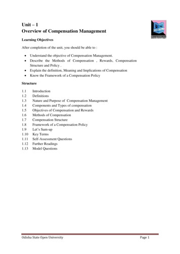
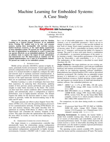
has two wires – one for clock, and the other is the data line, which is bi-directional – this beingthe reason it is also sometimes (not always – there are a few conditions) called Two WireInterface (TWI). It is a pretty new and revolutionary technology invented by Philips.3. FireWire – Developed by Apple, they are high-speed buses capable of audio/video transmission.The bus contains a number of wires depending upon the port, which can be either a 4-pin one, ora 6-pin one, or an 8-pin one.4. Ethernet: Used mostly in LAN connections, the bus consists of 8 lines, or 4 Tx/Rx pairs.5. Universal serial bus (USB): This is the most popular of all. Is used for virtually all type ofconnections. The bus has 4 lines: VCC, Ground, Data , and Data-.
USB Pins6. RS-232 – Recommended Standard 232: The RS-232 is typically connected using a DB9connector, which has 9 pins, out of which 5 are input, 3 are output, and one is Ground. You canstill find this so-called “Serial” port in some old PCs. In our upcoming posts, we will discussmainly about RS232 and USART of AVR microcontrollers.
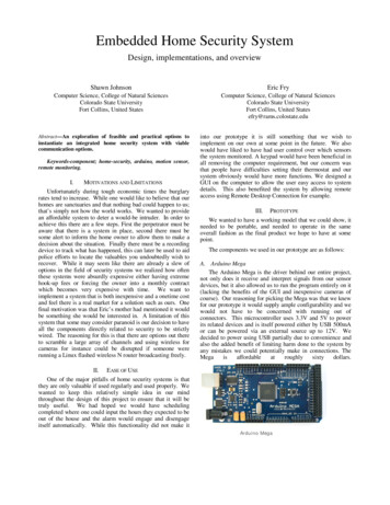
Unit-II - CPU Architecture of PIC MicrocontrollerPIC Microcontroller : PIC (Programmable Interface Controllers) microcontrollers are theworld’s smallest microcontrollers that can be programmed to carry out a huge range of tasks.These microcontrollers are found in many electronic devices such as phones, computer controlsystems, alarm systems, embedded systems, etc. Various types of microcontrollers exist, eventhough the best are found in the GENIE range of programmable microcontrollers.These microcontrollers are programmed and simulated by circuit-wizard software.Every PIC microcontroller architecture consists of some registers and stack where registersfunction as Random Access Memory( RAM) and stack saves the return addresses. The mainfeatures of PIC microcontrollers are RAM, flash memory, Timers/Counters, EEPROM, I/OPorts, USART, CCP (Capture/Compare/PWM module), SSP, Comparator, ADC (analog todigital converter), PSP(parallel slave port), LCD and ICSP (in circuit serial programming) The 8bit PIC microcontroller is classified into four types on the basis of internal architecture such asBase Line PIC, Mid Range PIC, Enhanced Mid Range PIC and PIC18Architecture of PIC MicrocontrollerThe PIC microcontroller architecture comprises of CPU, I/O ports, memory organization, A/Dconverter, timers/counters, interrupts, serial communication, oscillator and CCP module whichare discussed in detailed below.
CPU (Central Processing Unit)It is not different from other microcontrollers CPU and the PIC microcontroller CPU consists ofthe ALU, CU, MU and accumulator, etc. Arithmetic logic unit is mainly used for arithmeticoperations and to take logical decisions. Memory is used for storing the instructions afterprocessing. To control the internal and external peripherals, control unit is used which areconnected to the CPU and the accumulator is used for storing the results and further process.Memory OrganizationThe memory module in the PIC microcontroller architecture consists of RAM (Random AccessMemory), ROM (Read Only Memory) and STACK.Random Access Memory (RAM)RAM is an unstable memory which is used to store the data temporarily in its registers. TheRAM memory is classified into two banks, and each bank consists of so many registers. TheRAM registers are classified into two types: Special Function Registers (SFR) and GeneralPurpose Registers (GPR).General Purpose Registers (GPR)These registers are used for general purpose only as the name implies. For example, if we wantto multiply two numbers by using the PIC microcontroller. Generally, we use registers formultiplying and storing the numbers in other registers. So these registers don’t have any specialfunction,- CPU can easily access the data in the registers. Special Function RegistersThese registers are used for special purposes only as the name SFR implies. These registers willperform according to the functions assigned to them, and they cannot be used as normalregisters. For example, if you cannot use the STATUS register for storing the data, theseregisters are used for showing the operation or status of the program. So, user cannot change thefunction of the SFR; the function is given by the retailer at the time of manufacturing.
Memory OrganizationRead Only Memory (ROM)Read only memory is a stable memory which is used to store the data permanently. InPIC microcontrollerarchitecture, the architecture ROM stores the instructions or program,according to the program the microcontroller acts. The ROM is also called as program memory,wherein the user will write the program for microcontroller and saves it permanently, and finallythe program is executed by the CPU. The microcontrollers performance depends on theinstruction, which is executed by the CPU.Electrically Erasable Programmable Read Only Memory (EEPROM)In the normal ROM, we can write the program for only once we cannot use againthe microcontroller for multiple times. But, in the EEPROM, we can program the ROM multipletimes.Flash MemoryFlash memory is also programmable read only memory (PROM) in which we can read, write anderase the program thousands of times. Generally, the PIC microcontroller uses this type of ROM.StackWhen an interrupt occurs, first the PIC microcontroller has to execute the interrupt and theexisting process address. Then that is being executed is stored in the stack. After completing the
execution of the interrupt, the microcontroller calls the process with the help of address, which isstored in the stack and get executes the process.I/O Ports The series of PIC16 consists of five ports such as Port A, Port B, Port C, Port D & Port E. Port A is an 16-bit port that can be used as input or output port based on the status of theTRISA (Tradoc Intelligence Support Activity) register. Port B is an 8- bit port that can be used as both input and output port. Port C is an 8-bit and the input of output operation is decided by the status of the TRISCregister. Port D is an 8-bit port acts as a slave port for connection to the microprocessor BUS. Port E is a 3-bit port which serves the additional function of the control signals to theanalog to digital converter.BUSBUS is used to transfer and receive the data from one peripheral to another. It is classifiedinto two types such as data bus and address.Data Bus: It is used for only transfer or receive the data.Address Bus: Address bus is used to transmit the memory address from the peripherals to theCPU. I/O pins are used to interface the external peripherals; UART and USART both are serialcommunication protocols which are used for interfacing serial devices like GSM, GPS,Bluetooth, IR , etc.
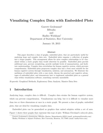
A/D convertersThe main intention of this analog to digital converter is to convert analog voltage values todigital voltage values. A/D module of PIC microcontroller consists of 5 inputs for 28 pin devicesand 8 inputs for 40 pin devices. The operation of the analog to digital converter is controlled byADCON0 and ADCON1 special registers. The upper bits of the converter are stored in registerADRESH and lower bits of the converter are stored in register ADRESL. For this operation, itrequires 5V of an analog reference voltage.A/D CONVERTERTimers/ CountersPIC microcontroller has four timer/counters wherein the one 8-bit timer and the remaining timershave the choice to select 8 or 16-bit mode. Timers are used for generating accuracy actions, forexample, creating specific time delays between two operations.InterruptsPIC microcontroller consists of 20 internal interrupts and three external interrupt sources whichare associated with different peripherals like ADC, USART, Timers, and so on.Serial Communication USART: The name USART stands for Universal synchronous and AsynchronousReceiver and Transmitter which is a serial communication for two protocols. It is used
for transmitting and receiving the data bit by bit over a single wire with respect to clockpulses. The PIC microcontroller has two pins TXD and RXD. These pins are used fortransmitting and receiving the data serially. SPI Protocol: The term SPI stands for Serial Peripheral Interface. This protocol is usedto send data between PIC microcontroller and other peripherals such as SDcards, sensors andshiftregisters.PIC microcontroller supportthreewireSPIcommunications between two devices on a common clock source. The data rate of SPIprotocol is more than that of the USART. I2C Protocol: The term I2C stands for Inter Integrated Circuit , and it is a serial protocolwhich is used to connect low speed devices such as EEPROMS, microcontrollers, A/Dconverters, etc. PIC microcontroller support two wire Interface or I2C communicationbetween two devices which can work as both Master and Slave device.Serial CommunicationOscillatorsOscillators are used for timing generation. Pic microcontroller consist of external oscillators likeRC oscillators or crystal oscillators. Where the crystal oscillator is connected between the twooscillator pins. The value of the capacitor is connected to every pin that decides the mode of theoperation of the oscillator. The modes are crystal mode, high-speed mode and the low-powermode. In case of RC oscillators, the value of the resistor & capacitor determine the clockfrequency and the range of clock frequency is 30KHz to 4MHz.
CCP moduleThe name CCP module stands for capture/compare/PWM where it works in three modes suchas capture mode, compare mode and PWM mode. Capture Mode: Capture mode captures the time of arrival of a signal, or in other words,when the CCP pin goes high, it captures the value of the Timer1. Compare Mode: Compare mode acts as an analog comparator. When the timer1 valuereaches a certain reference value, then it generates an output. PWM Mode: PWM mode provides pulse width modulated output with a 10-bitresolution and programmable duty cycle.PIC Microcontroller ApplicationsThe PIC microcontroller projects can be used in different applications, such as peripherals, audioaccessories, video games, etc. For better understanding of this PIC microcontroller, the followingproject demonstrates PIC microcontroller’s operations.Street Light that Glows on Detecting Vehicle Movement:The main intention of this project is to detect the movement of vehicles on highways to switchon a block of street lights ahead of it, and also switch off the trailing lights to conserve energy. Inthis project, a PIC microcontroller is done by using assembly language or embedded C.The power supply gives the power to the total circuit by stepping down, rectifying, filtering andregulating AC mains supply. When there are no vehicles on highway, then all lights will turnOFF so that the power can be conserved. The IR sensors are placed on the road to sense thevehicle movement. When there are vehicles on highway, then the IR sensor senses the vehiclemovement immediately, it sends the commands to the PIC microcontroller to switch ON/OFF theLEDs. A bunch of LEDS will be turned on when a vehicle come near to the sensor and once thevehicle passes away from the sensor the intensity will become lower than the LEDs will turnOFF
Advantages of PIC Microcontroller: PIC microcontrollers are consistent and faulty of PIC percentage is very less. Theperformance of the PIC microcontroller is very fast because of using RISC architecture. When comparing to other microcontrollers, power consumption is very less andprogramming is also very easy. Interfacing of an analog device is easy without any extra circuitryDisadvantages of PIC Microcontroller: The length of the program is high due to using RISC architecture (35 instructions) One single accumulator is present and program memory
Disadvantages High development effort Larger time to market Basic Structure of an Embedded System The following illustration shows the basic structure of an embedded system Sensor It measures the physical quantity and converts it to an electrical signal which can be read by an observ