Transcription
Data Communications & NetworksSession 7 – Main ThemeNetworks: Part ICircuit Switching, Packet Switching, The Network LayerDr. Jean-Claude FranchittiNew York UniversityComputer Science DepartmentCourant Institute of Mathematical SciencesAdapted from course textbook resourcesComputer Networking: A Top-Down Approach, 5/ECopyright 1996-2009J.F. Kurose and K.W. Ross, All Rights Reserved1Agenda11SessionSession OverviewOverview22NetworksNetworks PartPart 1133SummarySummary andand ConclusionConclusion2
What is the class about? Course description and syllabus:» http://www.nyu.edu/classes/jcf/g22.2262-001/» /index.html Textbooks:» Computer Networking: A Top-Down Approach (5th Edition)James F. Kurose, Keith W. RossAddison WesleyISBN-10: 0136079679, ISBN-13: 978-0136079675, 5th Edition (03/09)3Course Overview Computer Networks and the Internet Application Layer Fundamental Data Structures: queues, ring buffers, finite state machines Data Encoding and Transmission Local Area Networks and Data Link Control Wireless Communications Packet Switching OSI and Internet Protocol Architecture Congestion Control and Flow Control Methods Internet Protocols (IP, ARP, UDP, TCP) Network (packet) Routing Algorithms (OSPF, Distance Vector) IP Multicast Sockets4
Networks Part 1 Session in Brief Understand principles behind network layer services: Network layer service models Forwarding versus routing How a router works Instantiation, implementation in the Internet Conclusion5Icons / MetaphorsInformationCommon RealizationKnowledge/Competency PatternGovernanceAlignmentSolution Approach66
Agenda11SessionSession OverviewOverview22NetworksNetworks PartPart 1133SummarySummary andand ConclusionConclusion7Networks Part 1 Agenda Introduction Virtual circuit and datagram networks What’s inside a router IP: Internet Protocol Datagram format IPv4 addressing ICMP IPv68
Switching Networks Long distance transmission is typically done overa network of switched nodes Nodes not concerned with content of data End devices are stations Computer, terminal, phone, etc. A collection of nodes and connections is acommunications network Data routed by being switched from node tonode9Technology Two different switching technologies Circuit switching Packet switching10
Simple Switched Network11Circuit Switching Dedicated communication path between twostations (during conversation) Three phases Establish Transfer Disconnect Must have switching capacity and channelcapacity to establish connection Must have intelligence to work out routing12
Circuit Switching - Issues Circuit switching is inefficient (designed forvoice) Resources dedicated to a particular call Much of the time a data connection is idle Data rate is fixed Both ends must operate at the same rate Set up (connection) takes time Once connected, transfer is transparent13Packet Switching – Basic Operation Data transmitted in small packets Typically 1000 octets Longer messages split into series of packets Each packet contains a portion of user data plussome control info Control info Routing (addressing) info Packets are received, stored briefly (buffered)and passed on to the next node Store and forward14
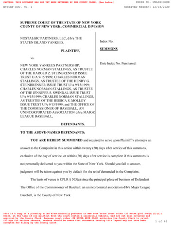
Use of Packets15Network layer transport segment fromsending to receiving host on sending sideencapsulates segmentsinto datagrams on receiving side, deliverssegments to transportlayer network layer protocols inevery host, router router examines headerfields in all IP datagramspassing through itapplicationtransportnetworkdata linkphysicalnetworkdata linkphysicalnetworkdata linkphysicalnetworkdata linkphysicalnetworkdata linkphysicalnetworkdata linkphysicalnetworknetworkdata linkdata linkphysicalphysicalnetworkdata linkphysicalnetworkdata linkphysicalnetworkdata linkphysicalnetworkdata linkphysicalapplicationtransportnetworkdata linkphysical16
Two Key Network-Layer Functionsanalogy: forwarding: movepackets fromrouter’s input toappropriate routeroutput routing: process ofplanning trip fromsource to dest forwarding: process routing: determineof getting throughroute taken bysingle interchangepackets from sourceto dest.» routing algorithms17Interplay between routing and forwardingrouting algorithmlocal forwarding tableheader value output link01000101011110013221value in arrivingpacket’s header011113 218
Connection setup 3rd important function in some networkarchitectures:» ATM, frame relay, X.25 before datagrams flow, two end hosts andintervening routers establish virtual connection» routers get involved network vs transport layer connection service:» network: between two hosts (may also involveintervening routers in case of VCs)» transport: between two processes19Network service modelQ: What service model for “channel” transportingdatagrams from sender to receiver?Example services forindividualdatagrams: guaranteed delivery guaranteed deliverywith less than 40msec delayExample services for aflow of datagrams: in-order datagramdelivery guaranteedminimum bandwidthto flow restrictions onchanges in interpacket spacing20
Network layer service ntees ?CongestionBandwidth Loss Order Timing feedbackbest effort oyesnono (inferredvia s Part 1 Agenda Introduction Virtual circuit and datagram networks What’s inside a router IP: Internet Protocol Datagram format IPv4 addressing ICMP IPv622
Network layer connection and connection-less service datagram network provides network-layerconnectionless service VC network provides network-layerconnection service analogous to the transport-layer services,but:» service: host-to-host» no choice: network provides one or the other» implementation: in network core23Virtual circuits“source-to-dest path behaves much like telephonecircuit”» performance-wise» network actions along source-to-dest path call setup, teardown for each call before data can flow each packet carries VC identifier (not destination hostaddress) every router on source-dest path maintains “state” foreach passing connection link, router resources (bandwidth, buffers) may beallocated to VC (dedicated resources predictableservice)24
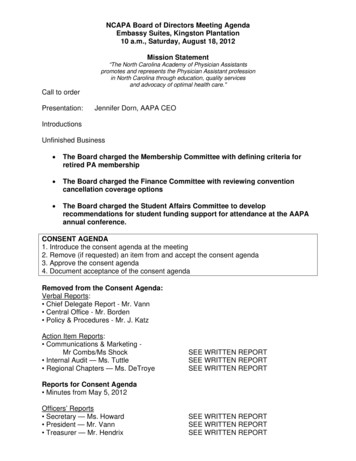
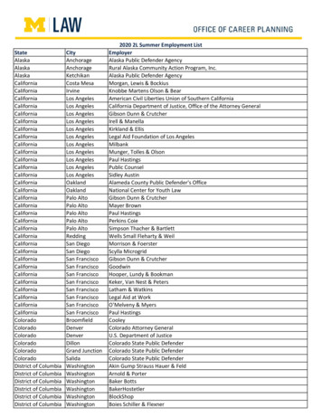
VC implementationa VC consists of:1. path from source to destination2. VC numbers, one number for each link alongpath3. entries in forwarding tables in routers alongpath packet belonging to VC carries VCnumber (rather than dest address) VC number can be changed on each link.» New VC number comes from forwardingtable25Forwarding tableVC number22121Forwarding table innorthwest router:Incoming interface1231 2323interfacenumberIncoming VC #1263797 Outgoing interface3123 Outgoing VC #22181787 Routers maintain connection state information!26
Virtual circuits: signaling protocols used to setup, maintain teardown VC used in ATM, frame-relay, X.25 not used in today’s Internetapplicationtransport 5. Data flow beginsnetwork 4. Call connecteddata link 1. Initiate callphysical6. Receive data application3. Accept call transport2. incoming call networkdata linkphysical27Datagram networks no call setup at network layer routers: no state about end-to-end connections» no network-level concept of “connection” packets forwarded using destination host address» packets between same source-dest pair may take differentpathsapplicationtransportnetworkdata link 1. Send dataphysicalapplicationtransport2. Receive data networkdata linkphysical28
Forwarding table4 billionpossible entriesDestination Address RangeLink Interface11001000 00010111 00010000 00000000through11001000 00010111 00010111 11111111011001000 00010111 00011000 00000000through11001000 00010111 00011000 11111111111001000 00010111 00011001 00000000through11001000 00010111 00011111 111111112otherwise329Longest prefix matchingPrefix Match11001000 00010111 0001011001000 00010111 0001100011001000 00010111 00011otherwiseLink Interface0123ExamplesDA: 11001000 00010111 00010110 10100001Which interface?DA: 11001000 00010111 00011000 10101010Which interface?30
Datagram or VC network: why?Internet (datagram)ATM (VC) data exchange among evolved from telephonycomputers human conversation:» “elastic” service, no strict» strict timing, reliabilitytiming req.requirements “smart” end systems» need for guaranteed(computers)service» can adapt, perform control, “dumb” end systemserror recovery» telephones» simple inside network,» complexity insidecomplexity at “edge”network many link types» different characteristics» uniform service difficult31Networks Part 1 Agenda Introduction Virtual circuit and datagram networks What’s inside a router IP: Internet Protocol Datagram format IPv4 addressing ICMP IPv632
Router Architecture OverviewTwo key router functions: run routing algorithms/protocol (RIP, OSPF,BGP) forwarding datagrams from incoming tooutgoing link33Input Port FunctionsPhysical layer:bit-level receptionData link layer:e.g., Ethernet(see TextbookChapter 5)Decentralized switching: given datagram dest., lookup output portusing forwarding table in input port memory goal: complete input port processing at ‘linespeed’ queuing: if datagrams arrive faster thanforwarding rate into switch fabric34
Three types of switching fabrics35Switching Via MemoryFirst generation routers: traditional computers with switching under directcontrol of CPU packet copied to system’s memory speed limited by memory bandwidth (2 bus crossingsper datagram)InputPortMemoryOutputPortSystem Bus36
Switching Via a Bus datagram from input portmemoryto output port memory via ashared bus bus contention: switchingspeed limited by bus bandwidth 32 Gbps bus, Cisco 5600:sufficient speed for access andenterprise routers37Switching Via An Interconnection Network overcome bus bandwidth limitations Banyan networks, other interconnection netsinitially developed to connect processors inmultiprocessor advanced design: fragmenting datagram intofixed length cells, switch cells through thefabric. Cisco 12000: switches 60 Gbps through theinterconnection network38
Output Ports Buffering required when datagrams arrive fromfabric faster than the transmission rate Scheduling discipline chooses among queueddatagrams for transmission39Output port queueing buffering when arrival rate via switch exceedsoutput line speed queueing (delay) and loss due to output portbuffer overflow!40
How much buffering? RFC 3439 rule of thumb: averagebuffering equal to “typical” RTT (say 250msec) times link capacity C» e.g., C 10 Gps link: 2.5 Gbit buffer Recent recommendation: with N flows,buffering equal toRTT. CN41Input Port Queuing Fabric slower than input ports combined - queueingmay occur at input queues Head-of-the-Line (HOL) blocking: queued datagram atfront of queue prevents others in queue from movingforward queueing delay and loss due to input buffer overflow!42
Networks Part 1 Agenda Introduction Virtual circuit and datagram networks What’s inside a router IP: Internet Protocol Datagram format IPv4 addressing ICMP IPv643The Internet Network layerHost, router network layer functions:Transport layer: TCP, UDPNetworklayerIP protocol addressing conventions datagram format packet handling conventionsRouting protocols path selection RIP, OSPF, BGPforwardingtableICMP protocol error reporting router “signaling”Link layerphysical layer44
Networks Part 1 Agenda Introduction Virtual circuit and datagram networks What’s inside a router IP: Internet Protocol Datagram format IPv4 addressing ICMP IPv645IP datagram formatIP protocol versionnumberheader length(bytes)“type” of datamax numberremaining hops(decremented ateach router)upper layer protocolto deliver payload tohow much overheadwith TCP? 20 bytes of TCP 20 bytes of IP 40 bytes applayer overhead32 bitsver head. type oflen servicelengthfragment16-bit identifier flgsoffsettime to upperheaderlayerlivechecksumtotal datagramlength (bytes)forfragmentation/reassembly32 bit source IP address32 bit destination IP addressOptions (if any)data(variable length,typically a TCPor UDP segment)E.g. timestamp,record routetaken, specifylist of routersto visit.46
IP Fragmentation & Reassembly network links have MTU(max.transfer size) - largestpossible link-level frame.» different link types,different MTUs large IP datagram divided(“fragmented”) within net» one datagram becomesseveral datagrams» “reassembled” only atfinal destination» IP header bits used toidentify, order relatedfragmentsfragmentation:in: one large datagramout: 3 smaller datagramsreassembly47IP Fragmentation and ReassemblyExample 4000 bytedatagram MTU 1500bytes1480 bytes indata fieldoffset 1480/8length ID fragflag offset 4000 x 0 0One large datagram becomesseveral smaller datagramslength ID fragflag offset 1500 x 1 0length ID fragflag offset 1500 x 1 185length ID fragflag offset 1040 x 0 37048
Networks Part 1 Agenda Introduction Virtual circuit and datagram networks What’s inside a router IP: Internet Protocol Datagram format IPv4 addressing ICMP IPv649IP Addressing: introduction IP address: 32-bitidentifier for host,router interface interface: connectionbetween host/routerand physical 23.1.2.9223.1.3.27223.1.2.2» router’s typically have223.1.3.2223.1.3.1multiple interfaces» host typically has oneinterface» IP addresses associated223.1.1.1 11011111 00000001 00000001 00000001with each interface22311150
Subnets IP address:» subnet part (highorder bits)» host part (low 1.2.9223.1.2.2223.1.3.27subnet What’s a subnet ?» device interfaceswith same subnetpart of IP address» can physically reacheach other withoutintervening router223.1.2.1223.1.3.2223.1.3.1network consisting of 3 subnets51Subnets223.1.1.0/24Recipe To determine thesubnets, detacheach interface fromits host or router,creating islands ofisolated networks.Each isolatednetwork is called asubnet.223.1.2.0/24223.1.3.0/24Subnet mask: /2452
Subnets223.1.1.2How .2.1223.1.3.27223.1.2.2223.1.3.1223.1.3.253IP addressing: CIDRCIDR: Classless InterDomain Routing» subnet portion of address of arbitrary length» address format: a.b.c.d/x, where x is # bits insubnet portion of addresssubnetparthostpart11001000 00010111 00010000 00000000200.23.16.0/2354
IP addresses: how to get one?Q: How does a host get IP address? hard-coded by system admin in a file» Windows: control-panel- network configuration- tcp/ip- properties» UNIX: /etc/rc.config DHCP: Dynamic Host Configuration Protocol:dynamically get address from as server» “plug-and-play”55DHCP: Dynamic Host Configuration ProtocolGoal: allow host to dynamically obtain its IP address fromnetwork server when it joins networkCan renew its lease on address in useAllows reuse of addresses (only hold address while connected an “on”)Support for mobile users who want to join network (more shortly)DHCP overview:» host broadcasts “DHCP discover” msg [optional]» DHCP server responds with “DHCP offer” msg [optional]» host requests IP address: “DHCP request” msg» DHCP server sends address: “DHCP ack” msg56
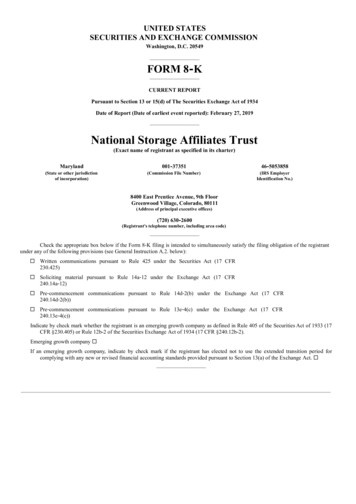
DHCP client-server .2E223.1.3.2arriving DHCPclient needsaddress in thisnetwork57DHCP client-server scenarioDHCP server: 223.1.2.5DHCP discoversrc : 0.0.0.0, 68dest.: 255.255.255.255,67yiaddr: 0.0.0.0transaction ID: 654arrivingclientDHCP offersrc: 223.1.2.5, 67dest: 255.255.255.255, 68yiaddrr: 223.1.2.4transaction ID: 654Lifetime: 3600 secsDHCP requesttimesrc: 0.0.0.0, 68dest:: 255.255.255.255, 67yiaddrr: 223.1.2.4transaction ID: 655Lifetime: 3600 secsDHCP ACKsrc: 223.1.2.5, 67dest: 255.255.255.255, 68yiaddrr: 223.1.2.4transaction ID: 655Lifetime: 3600 secs58
DHCP: more than IP addressDHCP can return more than just allocated IPaddress on subnet:» address of first-hop router for client» name and IP address of DNS sever» network mask (indicating network versus hostportion of address)59DHCP: exampleDHCPUDPIPEthPhyDHCPDHCPDHCPDHCP connecting laptop needsits IP address, addr offirst-hop router, addr ofDNS server: use uter(runs DHCP) DHCP requestencapsulated in UDP,encapsulated in IP,encapsulated in 802.1 EthernetEthernet framebroadcast (dest:FFFFFFFFFFFF) on LAN,received at routerrunning DHCPserver Ethernetdemux’edto IPdemux’ed, UDPdemux’ed to DHCP60
DHCP: DHCPDHCPDHCPUDPIPEthPhy DCP server formulatesDHCP ACK containingclient’s IP address, IPaddress of first-hop routerfor client, name & IPaddress of DNS serverrouter(runs DHCP) encapsulation of DHCPserver, frame forwardedto client, demux’ing up toDHCP at client client now knows its IPaddress, name and IPaddress of DSN server,IP address of its first-hoprouter61DHCP: wireshark output(home LAN)replyMessage type: Boot Request (1)Hardware type: EthernetHardware address length: 6Hops: 0Transaction ID: 0x6b3a11b7Seconds elapsed: 0Bootp flags: 0x0000 (Unicast)Client IP address: 0.0.0.0 (0.0.0.0)Your (client) IP address: 0.0.0.0 (0.0.0.0)Next server IP address: 0.0.0.0 (0.0.0.0)Relay agent IP address: 0.0.0.0 (0.0.0.0)Client MAC address: Wistron 23:68:8a (00:16:d3:23:68:8a)Server host name not givenBoot file name not givenMagic cookie: (OK)Option: (t 53,l 1) DHCP Message Type DHCP RequestOption: (61) Client identifierLength: 7; Value: 010016D323688A;Hardware type: EthernetClient MAC address: Wistron 23:68:8a (00:16:d3:23:68:8a)Option: (t 50,l 4) Requested IP Address 192.168.1.101Option: (t 12,l 5) Host Name "nomad"Option: (55) Parameter Request ListLength: 11; Value: 010F03062C2E2F1F21F92B1 Subnet Mask; 15 Domain Name3 Router; 6 Domain Name Server44 NetBIOS over TCP/IP Name Server requestMessage type: Boot Reply (2)Hardware type: EthernetHardware address length: 6Hops: 0Transaction ID: 0x6b3a11b7Seconds elapsed: 0Bootp flags: 0x0000 (Unicast)Client IP address: 192.168.1.101 (192.168.1.101)Your (client) IP address: 0.0.0.0 (0.0.0.0)Next server IP address: 192.168.1.1 (192.168.1.1)Relay agent IP address: 0.0.0.0 (0.0.0.0)Client MAC address: Wistron 23:68:8a (00:16:d3:23:68:8a)Server host name not givenBoot file name not givenMagic cookie: (OK)Option: (t 53,l 1) DHCP Message Type DHCP ACKOption: (t 54,l 4) Server Identifier 192.168.1.1Option: (t 1,l 4) Subnet Mask 255.255.255.0Option: (t 3,l 4) Router 192.168.1.1Option: (6) Domain Name ServerLength: 12; Value: 445747E2445749F244574092;IP Address: 68.87.71.226;IP Address: 68.87.73.242;IP Address: 68.87.64.146Option: (t 15,l 20) Domain Name "hsd1.ma.comcast.net."62
IP addresses: how to get one?Q: How does network get subnet part of IPaddr?A: gets allocated portion of its providerISP’s address spaceISP's block11001000 00010111 00010000 00000000200.23.16.0/20Organization 0Organization 1Organization 2.11001000 00010111 00010000 0000000011001000 00010111 00010010 0000000011001000 00010111 00010100 00000000 . .200.23.16.0/23200.23.18.0/23200.23.20.0/23 .Organization 711001000 00010111 00011110 00000000200.23.30.0/2363Hierarchical addressing: route aggregationHierarchical addressing allows efficient advertisement of routinginformation:Organization 0200.23.16.0/23Organization 1200.23.18.0/23Organization 2200.23.20.0/23Organization 7.Fly-By-Night-ISP“Send me anythingwith 30.0/23ISPs-R-Us“Send me anythingwith addressesbeginning199.31.0.0/16”64
Hierarchical addressing: more specific routesISPs-R-Us has a more specific route to Organization 1Organization 0200.23.16.0/23Organization 2200.23.20.0/23Organization 7.Fly-By-Night-ISP“Send me anythingwith 30.0/23ISPs-R-UsOrganization 1200.23.18.0/23“Send me anythingwith addressesbeginning 199.31.0.0/16or 200.23.18.0/23”65IP addressing: the last word.Q: How does an ISP get block ofaddresses?A: ICANN: Internet Corporation for AssignedNames and Numbers» allocates addresses» manages DNS» assigns domain names, resolves disputes66
NAT: Network Address Translationrest ofInternetlocal network(e.g., home .710.0.0.3All datagrams leaving localnetwork have same single sourceNAT IP address: 138.76.29.7,different source port numbersDatagrams with source ordestination in this networkhave 10.0.0/24 address forsource, destination (as usual)67NAT: Network Address Translation Motivation: local network uses just one IP addressas far as outside world is concerned:» range of addresses not needed from ISP: justone IP address for all devices» can change addresses of devices in localnetwork without notifying outside world» can change ISP without changing addresses ofdevices in local network» devices inside local net not explicitlyaddressable, visible by outside world (a securityplus).68
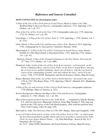
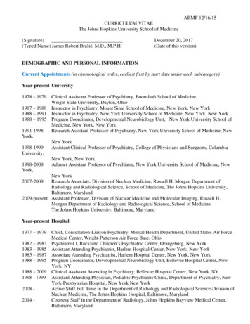
NAT: Network Address TranslationImplementation: NAT router must:» outgoing datagrams: replace (source IP address, port #)of every outgoing datagram to (NAT IP address, newport #). . . remote clients/servers will respond using (NAT IPaddress, new port #) as destination addr.» remember (in NAT translation table) every (source IPaddress, port #) to (NAT IP address, new port #)translation pair» incoming datagrams: replace (NAT IP address, new port#) in dest fields of every incoming datagram withcorresponding (source IP address, port #) stored in NATtable69NAT: Network Address Translation2: NAT routerchanges datagramsource addr from10.0.0.1, 3345 to138.76.29.7, 5001,updates table2NAT translation tableWAN side addrLAN side addr1: host 10.0.0.1sends datagram to128.119.40.186, 80138.76.29.7, 5001 10.0.0.1, 3345 S: 10.0.0.1, 3345D: 128.119.40.186, 80S: 138.76.29.7, 5001D: 128.119.40.186, 80138.76.29.7S: 128.119.40.186, 80D: 138.76.29.7, 50013: Reply arrivesdest. address:138.76.29.7, 50013110.0.0.4S: 128.119.40.186, 80D: 10.0.0.1, 334510.0.0.110.0.0.2410.0.0.34: NAT routerchanges datagramdest addr from138.76.29.7, 5001 to 10.0.0.1, 334570
NAT: Network Address Translation 16-bit port-number field:» 60,000 simultaneous connections with asingle LAN-side address! NAT is controversial:» routers should only process up to layer 3» violates end-to-end argument NAT possibility must be taken into account by appdesigners, eg, P2P applications» address shortage should instead be solved byIPv671NAT traversal problem client wants to connect toserver with address 10.0.0.1» server address 10.0.0.1 local toLAN (client can’t use it asdestination addr)» only one externally visibleNATted address: 138.76.29.7 solution 1: statically configureNAT to forward incomingconnection requests at givenport to � e.g., (123.76.29.7, port 2500)always forwarded to 10.0.0.1port 2500072
NAT traversal problem solution 2: Universal Plug andPlay (UPnP) Internet GatewayDevice (IGD) Protocol. AllowsNATted host to: learn public IP address(138.76.29.7) add/remove port mappings(with lease times)10.0.0.1IGD10.0.0.4138.76.29.7NATrouteri.e., automate static NAT portmap configuration73NAT traversal problem solution 3: relaying (used in Skype)» NATed client establishes connection to relay» External client connects to relay» relay bridges packets between to connections2. connection torelay initiatedby clientClient3. relayingestablished1. connection torelay initiatedby NATted host138.76.29.710.0.0.1NATrouter74
Networks Part 1 Agenda Introduction Virtual circuit and datagram networks What’s inside a router IP: Internet Protocol Datagram format IPv4 addressing ICMP IPv675ICMP: Internet Control Message Protocol used by hosts & routers tocommunicate network-levelinformation» error reporting:unreachable host, network,port, protocol» echo request/reply (usedby ping) network-layer “above” IP:» ICMP msgs carried in IPdatagrams ICMP message: type, codeplus first 8 bytes of IPdatagram causing ionecho reply (ping)dest. network unreachabledest host unreachabledest protocol unreachabledest port unreachabledest network unknowndest host unknownsource quench (congestioncontrol - not used)echo request (ping)route advertisementrouter discoveryTTL expiredbad IP header76
Traceroute and ICMP Source sends series ofUDP segments to dest» First has TTL 1» Second has TTL 2, etc.» Unlikely port number When nth datagramarrives to nth router:» Router discards datagram» And sends to source anICMP message (type 11,code 0)» Message includes name ofrouter& IP address When ICMP messagearrives, source calculatesRTT Traceroute does this 3timesStopping criterion UDP segment eventuallyarrives at destination host Destination returns ICMP“host unreachable”packet (type 3, code 3) When source gets thisICMP, stops.77Networks Part 1 Agenda Introduction Virtual circuit and datagram networks What’s inside a router IP: Internet Protocol Datagram format IPv4 addressing ICMP IPv678
IPv6 Initial motivation: 32-bit address spacesoon to be completely allocated. Additional motivation:» header format helps speedprocessing/forwarding» header changes to facilitate QoSIPv6 datagram format:» fixed-length 40 byte header» no fragmentation allowed79IPv6 Header (Cont)Priority: identify priority among datagrams in flowFlow Label: identify datagrams in same “flow.”(concept of“flow” not well defined).Next header: identify upper layer protocol for data80
Other Changes from IPv4 Checksum: removed entirely to reduceprocessing time at each hop Options: allowed, but outside of header,indicated by “Next Header” field ICMPv6: new version of ICMP» additional message types, e.g. “Packet TooBig”» multicast group management functions81Transition From IPv4 To IPv6 Not all routers can be upgradedsimultaneous» no “flag days”» How will the network operate with mixed IPv4and IPv6 routers? Tunneling: IPv6 carried as payload in IPv4datagram among IPv4 routers82
Tunneling (1/2)Logical view:Physical lIPv4IPv483Tunneling (2/2)Logical view:Physical view:ABIPv6IPv6ABCIPv6IPv6IPv4Flow: XSrc: ADest: :BDest: ESrc:BDest: EFlow: XSrc: ADest: FFlow: XSrc: ADest: FdatadataB-to-C:IPv6 insideIPv4B-to-C:IPv6 insideIPv4Flow: XSrc: ADest: FdataE-to-F:IPv684
Agenda11SessionSession OverviewOverview22NetworksNetworks PartPart 1133SummarySummary andand ConclusionConclusion85Summary Introduction Virtual circuit and datagram networks What’s inside a router IP: Internet Protocol Datagram format IPv4 addressing ICMP IPv686
Assignments & Readings Readings» Chapter 4 Assignment #4» Due March 25 201087Next Session: Networks - Part II88
2. VC numbers, one number for each link along path 3. entries in forwarding tables in routers along path packet belonging to VC carries VC number (rather than dest address) VC number can be changed on each link. » New VC number comes from forwarding table 26 Forwarding table 12 22 32 1 2 3 VC number interface number