Transcription
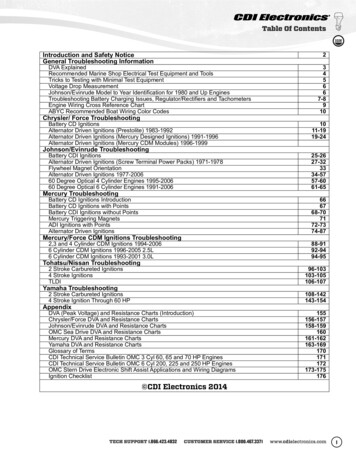
Table Of ContentsIntroduction and Safety NoticeGeneral Troubleshooting Information2DVA ExplainedRecommended Marine Shop Electrical Test Equipment and ToolsTricks to Testing with Minimal Test EquipmentVoltage Drop MeasurementJohnson/Evinrude Model to Year Identification for 1980 and Up EnginesTroubleshooting Battery Charging Issues, Regulator/Rectifiers and TachometersEngine Wiring Cross Reference ChartABYC Recommended Boat Wiring Color CodesChrysler/ Force Troubleshooting345667-8910Battery CD IgnitionsAlternator Driven Ignitions (Prestolite) 1983-1992Alternator Driven Ignitions (Mercury Designed Ignitions) 1991-1996Alternator Driven Ignitions (Mercury CDM Modules) 1996-19991011-1919-24Battery CDI IgnitionsAlternator Driven Ignitions (Screw Terminal Power Packs) 1971-1978Flywheel Magnet OrientationAlternator Driven Ignitions 1977-200660 Degree Optical 4 Cylinder Engines 1995-200660 Degree Optical 6 Cylinder Engines 1991-200625-2627-323334-5757-6061-65Battery CD Ignitions IntroductionBattery CD Ignitions with PointsBattery CDI Ignitions without PointsMercury Triggering MagnetsADI Ignitions with PointsAlternator Driven Ignitions666768-707172-7374-872,3 and 4 Cylinder CDM Ignitions 1994-20066 Cylinder CDM Ignitions 1996-2005 2.5L6 Cylinder CDM Ignitions 1993-2001 3.0L88-9192-9494-95Johnson/Evinrude TroubleshootingMercury TroubleshootingMercury/Force CDM Ignitions TroubleshootingTohatsu/Nissan Troubleshooting2 Stroke Carbureted Ignitions4 Stroke IgnitionsTLDI96-103103-105106-1072 Stroke Carbureted Ignitions4 Stroke Ignition Through 60 HP108-142143-154DVA (Peak Voltage) and Resistance Charts (Introduction)Chrysler/Force DVA and Resistance ChartsJohnson/Evinrude DVA and Resistance ChartsOMC Sea Drive DVA and Resistance ChartsMercury DVA and Resistance ChartsYamaha DVA and Resistance ChartsGlossary of TermsCDI Technical Service Bulletin OMC 3 Cyl 60, 65 and 70 HP EnginesCDI Technical Service Bulletin OMC 6 Cyl 200, 225 and 250 HP EnginesOMC Stern Drive Electronic Shift Assist Applications and Wiring DiagramsIgnition 72173-175176Yamaha TroubleshootingAppendix CDI Electronics 2014TECH SUPPORT 1.866.423.4832CUSTOMER SERVICE 1.800.467.3371www.cdielectronics.com1
IntroductionIntroductionThe information contained in this Troubleshooting Guide has been compiled from various sources withinthe marine industry. Any reference to a specific product or brand is not intended for commercial purposes.References to test equipment and products are based upon the information available to the staff of CDIElectronics. This information is designed for use as a reference guide by a professional marinetechnician. CDI Electronics cannot be held liable for the misuse or abuse of the information containedherein. The staff tries to make the information as accurate as possible. However, CDI Electronics cannotassume responsibility for either the data accuracy or the consequences of the data’s application.All rights reserved. Reproduction or use, without express permission by CDI Electronics, Inc., of editorialor pictorial content, in any manner, is prohibited. CDI Electronics 2014Safety IssuesISBN: 978-0-9825359-1-2Always remember to treat the outboard engine with respect. The engine uses high voltage forignition and contains several moving components. Always be aware of moving mechanical parts,the surrounding area, and the position of your hands and body near the engine. Never touch electrical components with wet hands. Whenever the power source is not needed, disconnect the cable from the negative terminal. Never reverse the battery leads when you connect the battery or disconnect the terminals while theengine is running as severe damage to the electrical system can result. Never touch high-tension leads (spark plug leads) with any ungrounded tools while the engine isrunning. Never install equipment with requirements exceeding the generating power of the engine. Referencethe service manual for values. Attempt to protect the electronic components from water. Insure fuel lines, harnesses, and oil lines are properly routed. Failure to follow this rule could result ina fire hazard. Make sure all ground leads are clean and tight.NOTICE: The DVA readings in this book were compiled using the CDI DVA Adapter (511-9773 or511-9773NL) with a shielded Digital Multimeter. A Digital multimeter with peak voltage scale cannotbe used without the DVA as the meter is expecting a 60 hertz signal where the outboard can have anequivalent frequency of over 1000 hertz.(NOTE) The resistance readings are given for a room temperature of 68 F. Higher temperatures willcause a slightly higher resistance reading.Normally, DVA readings should always be taken with everything hooked up with the exception of the stopcircuit.2TROUBLESHOOTING GUIDEBETTER THAN THE OEM
DVA ExplainedDVA stands for Direct Voltage Adapter, which is used to measure peak AC voltage. This type ofmeasurement of AC voltage takes the absolute peak or highest value of the fluctuating AC voltage signal.Peak readings will be substantially higher than standard or RMS AC values and are typically used whentesting marine CD (capacitor discharge) ignition systems due to their high variance in frequency as RPMincreases and decreases.An example would be that the typical RMS AC reading of a wall outlet in North America is 120V.However, a DVA measurement of this same AC voltage would reveal that the peak of the AC sine wave istypically between 160-170V.Some meters are capable of reading DVA or peak voltage pulses. Many ignition system componentsproduce short, high frequency, AC voltage pulses. A peak-reading analog meter or DVA adapter pluggedinto a digital meter captures and holds the peak value of an AC sine wave long enough for the human eyeto see it displayed on the meter. A conventional meter is incapable of accurately measuring these shortduration voltage pulses. A peak-reading voltmeter has special circuits that allow the meter to capture themaximum voltage produced during these short duration pulses and display the voltage as DVA or peakvoltage. Failure to measure DVA correctly can cause good ignition components to be incorrectlydiagnosed as faulty.Typically, the only meters that have built-in peak reading capabilities are analog meters with built-in DVA.Digital meters do not normally have built-in peak reading capabilities. In order for a digital meter to readpeak voltage, one will need a DVA adapter, such as CDI part# 511-9773 or 511-9773NL.Using a DVA adapter, a digital meter must be set to its DC voltage scale. Peak AC voltage is themeasurement, but the DVA adapter has a built-in bridge rectifier, which converts AC to DC. The DCvoltage setting on a digital meter is required to accurately read DVA.CDI part# 511-9773 has built-in test leads.CDI part# 511-9773NL has banana jacks, which uses your existing meter’s test leads.NOTICE: The DVA readings in this book were compiled using the CDI DVAAdapter (511-9773 or 511-9773NL) with a shielded Digital Multimeter. A Digitalmultimeter with peak voltage scale cannot be used without the DVA as the meteris expecting a 60 hertz signal where the outboard can have an equivalentfrequency of over 1000 hertz.(NOTE) The resistance readings are given for a room temperature of 68 F. Highertemperatures will cause a slightly higher resistance reading.Normally, DVA readings should always be taken with everything hooked up withthe exception of the stop circuit.The CDI DVA adapter is specifically designed to work with shielded Digital Multimeters.This adapter will simplify the testing of electronic ignition systems, stators, sensors andcharging systems. The DVA readings will be approximately the same as any other DVAmeter and the specifications listed in the service manuals can be followed withoutproblems (Hopefully a little easier to you).TECH SUPPORT 1.866.423.4832CUSTOMER SERVICE 1.800.467.3371www.cdielectronics.com3
Marine Shop Recommended Tool ListPart Number511-4017CDI Electronics Marine Shop Recommended Tool ListDescriptionRemarks/UseOptical Sensor Tester511-4019Optical Sensor Tester511-5207A 1511-6996511-7800511-7900511-9764CDM Test HarnessRemote StarterRemote StarterRemote StarterNeon Spark Tester (1 Cyl)511-9766Sealed Spark Gap Tester511-9770Piercing Probes(Highly Recommended)Ammeter Adapter511-9772511-9773NLDVA (Peak Voltage)Adapter511-9775511-60ALoad ResistorCDI Electronics Meter520-ST80531-0118T 3DC Inductive Timing LightMarine EngineDiagnostic Software(M.E.D.S.)Used to set timing on a 4 or 6 Cyl engine or test optical sensors on thebench and on the engine. Unique buzzer allows you to set timing withouthaving to see the LED.Unique tester is used to test 3 Cyl optical sensors on the bench and on theengine.Test the CDM Module DVA on the engine and isolate the kill circuit.Controls most Johnson/Evinrude engines from 1969 thru 2006.Controls most Mercury engines from 1970 thru 1978.Controls most Mercury engines from 1979 thru 2000.Sealed single cylinder tester can be used in-line to the spark plug forengine running tests. (With removable ground clip.)Allows you to test up to 8 cylinders for cranking speed tests. Sealed designreduces the chances of injury and fire.Allows access to wires for testing without removing the connector. Tinyhole usually reseals itself when wire heats.Used with most Digital multimeters to measure amperage output of thecharging system or starter draw amperage.Unit automatically compensates for polarity. Can be used with most qualitymultimeters.To load the output of ignition modules when testing ignition coils.Most cost effective meter for marine use. Has voltage, temperature,amperage, ohms, and DVA readings (includes the 511-9773-NL DVAAdapter).DC powered timing light with a very bright strobe light.Software operates with Windows Microsoft operating systems. Readsand monitors failure codes on Mercury 1994 and newer EFI, 1997 andnewer Optimax, Verado, 2001-2006 4 Stroke Yamaha, Built Mercury,Yamaha HPDI 1998 & up, 4 Stroke V6 2000 & up, I3 & I4 4 Stroke 2008& up engines, Yamaha PWCs, Plus Mercruiser I/O engines using the 555ECM module, Johnson/Evinrude Ficht/E-TEC engines, Suzuki 4 Stroke,and MEFI 1-4 Sterndrives.New design prevents tipping over, and EZ-Fill calibrated check valvecreates air-lock to keep lube from running out while installing drain plug.Makes filling lower units easier.Repairable metal unit does both vacuum and pressure testing.New design has a high tensile strength poly coated woven belt for a moresecure grip of flywheel. Longer handle provides a more comfortable grip formore leverage with less effort.551-33-1Gearcase Filler WithCheck Valve551-34PV551-5110Pressure/Vacuum TesterFlywheel Holder553-2700Amphenol Pin Tool SetSet contains one each of 553-2697 (insertion), 553-2698 (pin removal),and 553-2699 (socket removal) tools.553-4994Gauge Ring911-9783912-9708961-0002991-9705Bullet Connector KitMarine Terminal KitTroubleshooting GuideDielectric GreaseUsed to set stator and trigger air gap on Johnson/Evinrude 2 Cyl / 2 Strokeengines from 1977-2006.Contains 10 pieces each of the male, female connectors and sleeves.Contains 100 pieces of hard to find terminals and heat shrink.Manual has detailed troubleshooting information and DVA charts.Used to keep water and corrosion out of connectors.Optional Equipment Upgrades4511-0300Infrared TemperatureMeterUsed to read engine, spark plug, lower unit, and hull temperature. Ideal forquickly measuring engine temperature.518-88-5Fluke 88 AutomotiveMeterUsed to check engine DVA, ohms, amps, pulse width, frequency,Temperature, Capacitance, diodes and engine RPM.520-ST84Timing Light w/TachEasily check engine timing in bright sunlight. Change the switch and readthe engine RPM.TROUBLESHOOTING GUIDEBETTER THAN THE OEM
Tricks to Testing with Minimal Test EquipmentTricks to Testing with Minimal Test Equipment All Engines Please keep detailed records when you repair an engine. If an engine comes in with one cylinder not firing,mark which one on the work order/history. Remember to check the compression of all cylinders! It does not make any sense to fix an ignition problemif the engine has a blown cylinder. Don’t forget low compression can be caused by something as simple asa bad starter, a low or weak battery. An engine requires air, fuel and spark (at the correct time) in order to run. Make sure the engine has allthree.If the engine has no spark on any cylinder, make sure to disconnect the stop circuit AT THE IGNITIONPACK! If the harness or ignition switch is bad, the pack will start firing when you do this.Intermittent Firing: This problem can be very hard to isolate. A good inductive tachometer can be used to comparethe RPM on all cylinders up through WOT (wide-open throttle). A significant difference in the RPM readings can helppinpoint a problem quickly. Visually Check the Stator, Trigger, Rectifier/Regulator and Flywheel: Cracks, burned areas and bubbles in oron the components indicate a problem. If the battery charge windings on the stator are dark brown, black or burnedon most or all of the posts, the rectifier/regulator is likely shorted as well. Any sign of rubbing on the outside of thestator indicates a problem in the upper or lower main bearings. A cracked trigger or outer charging magnets cancause many problems ranging from misfiring to no spark at all. Loose flywheel magnets can be dangerous, checkthe tightness of the bonding adhesive.Rectifier/Regulators can cause problems ranging from a high-speed miss to a total shutdown. An easy check is todisconnect the stator leads to the rectifier (Make sure to insulate them) and retest. If the problem is gone – replacethe rectifier/regulator.Johnson/EvinrudeOpen Timer Bases: When all cylinders spark with the spark plugs out, but will not with them installed, try re-gappingthe sensors using P/N: 553-9702 Gap Gauge. (See the section on OMC ADI Ignitions).Engines with S.L.O.W. Features: If the customer is complaining that the engine won’t rev up and shakes real bad,the S.L.O.W. function could be activating. If the engine is NOT overheating, a temperature sensor or VRO sensorfailing early can cause this problem. Disconnect the TAN wires at the power pack and retest. If the engine performsnormally, reconnect the tan wires one at a time until the problem recurs, then replace the last sensor you connected.Make sure that all of the TAN wires are located as far as possible from the spark plug wires. Also check the blockingdiode in the engine harness.Mercury 6 Cylinder Engines with ADI IgnitionsIf more than one cylinder is not firing: Replace BOTH switch boxes unless you can pin the problem down to thetrigger. Replacing just one switch box can result in damage to the engine if the remaining switch box on the enginehas a problem in the bias circuit.Always check the bias circuit: Disconnect the White/Black jumper between the switch boxes and check theresistance from the White/Black terminal on each switch box to engine ground. You should read 12-15,000 ohms onstock switch boxes, and 9,000-9,800 ohms on racing switch boxes. MAKE SURE THE READING IS THE SAME ONBOTH SWITCH BOXES! Any problem with the bias circuit and BOTH switch boxes must be replaced as a set.No Spark on 1, 3, 5 or 2, 4, 6: Swap the stator leads from one switch box to the other. If the problem moves,replace the stator. If the problem remains on the same cylinders, replace the switch box. If the stator is replaced andthe problem is still present, try another flywheel.No Spark on One Cylinder: This can be caused by a defective blocking diode in the other switch box. Disconnectthe White/Black jumper between the switch boxes and retest. If all cylinders are now firing, replace the switch boxthat was originally firing all three cylinders. To verify this condition, swap the trigger leads on the switch box that wasoriginally firing all three cylinders. If the miss moves to another cylinder, the switch box is bad.TECH SUPPORT 1.866.423.4832CUSTOMER SERVICE 1.800.467.3371www.cdielectronics.com5
Voltage Drop MeasurementStart by using a good digital auto-ranging voltmeter capable of reading 1/10th of a volt. The use of an auto-rangingmeter will allow for more accurate testing without damaging the meter due to an incorrect range setting.Remove the spark plug wires form the spark plugs and connect them to a spark gap tester and remove theemergency stop clip as well. This prevents the engine from starting and also reduces the chance of getting shockedby the ignition system.The use of an ohmmeter to test a conductor or switch contact for their condition is not the best tool to use. In mostcases, it is preferable to use a volt drop test to make sure the conductor, as well as the connection, is in goodcondition.Before testing, remove and clean all battery cables and connection points.Testing the Positive Battery Cable to the Engine1. Select the DC Volts position on the meter.2. Connect the Red (Positive) lead on the meter to the positive battery POST.3. Connect the Black (Negative) lead on the meter to the starter solenoid terminal where the positive battery cableis connected.4. Using a remote start switch, activate the starter solenoid to spin the engine and observe the reading on themeter. A reading above 0.6V indicates a bad cable or bad connection.A. If the meter reads above 0.6V, move the Black lead on the meter to the positive battery cable terminal onthe starter solenoid and retest. If the reading drops to below 0.6V, the cable connection is bad.B. If the meter still reads above 0.6V, move the Black lead on the meter to the positive battery cable terminalon the battery and retest. If the reading drops to below 0.6V, the cable is bad or undersized.(Service Note) A bad power connection to the ignition or battery charging system can be found by connecting theBlack lead on the meter to the power connection of the ignition system or charging system; then working your wayback to the battery positive post. At no time should you see a reading above 1V.Testing the Negative Battery Cable to the Engine1. Select the DC Volts position on the meter.2. Connect the Black (Negative) lead on the meter to the negative battery POST.3. Connect the Red (Positive) lead on the meter to the engine block where the negative battery cable isconnected.4. Using a remote start switch, activate the starter solenoid to spin the engine and observe the reading on themeter. A reading above 0.6V is an indicator of a bad cable or bad connection.A. If the meter reads above 0.6V, move the Red lead on the meter to the negative battery cable terminal on theengine block and retest. If the reading drops to below 0.6V, the cable connection is bad.B. If the meter still reads above 0.6V, move the Red lead on the meter to the negative battery cable terminal onthe battery and retest. If the reading drops to below 0.6V, the cable is bad or undersized.A bad ground connection to the ignition and battery charging system can be found by connecting the Red lead onthe meter to the ground connection of the ignition or battery charging system; then working your way back to thebattery negative post. At no time should you see a reading above 1V.Johnson/Evinrude Model to Year Identification for 1980 and newer : J150TTLCE would be a 1989 150 HP Johnson and aE175STEU would be a 1997 175 HP Evinruide.6TROUBLESHOOTING GUIDEBETTER THAN THE OEM
Battery DifferencesMaintenance-free batteries (gel cells / AGM / closed-case) have thin plates. They’re ideal for a charging system thatmaintains a typical charge between 12.5V – 14.4V, but not for outboards, where batteries are commonly drainedby accessories while fishing, etc. i.e. when there is no charge applied to a battery while the battery is in use. Itsthin plates cannot withstand constant discharging and charging. It will develop weak and/or dead cells due to thisbehavior.Maintenance-free batteries should not be used because their life span is shortened when used on an outboardapplication. A new fully-charged, maintenance-free battery will work fine at first, but under constant discharging andcharging, something that style battery is not designed for, it will eventually become weak and/or develop dead cells,thus unable to accept a full charge, thus putting a rectifier/regulator at extreme risk of failure.Non-maintenance-free batteries (lead-acid flooded cell; has vent caps on its top) have heavy, thick plates. They’reideal for outboards, where batteries are commonly drained by accessories while fishing, etc. i.e. when there is nocharge applied to a battery while the battery is in use. Its heavy plates can withstand constant discharging andcharging. These batteries have much more reserve time and are much more suited for this behavior.The recommended type of battery for outboards is a single (NOT more than one) 850 CCA dual purpose orcranking/starting non-maintenance-free battery. Make sure to charge any battery off of a battery charger BEFOREinstalling. NEVER allow the stator to charge a battery. The stator is designed to maintain the battery’s voltage at anoptimum charge. It’s not designed to charge a dead or weak battery. Make sure the battery is always charged off ofa battery charger before each use of the boat to maintain optimum performance and life of the battery, stator andregulator. If multiple accessories are used, a 2nd battery, NOT connected to the starting battery, is recommended. Ifdesired, a make-before-break switch can be used between the two batteries. Make sure to also charge this batteryoff of a battery charger before each use.NEVER jump-start a battery while an outboard engine is running. This can cause damage to the rectifier/regulator.Always use a battery charger to charge a battery. If no battery charger is available, the rectifier/regulator’s Red wiremay be disconnected while jump-starting to avoid damaging the rectifier/regulator.Troubleshooting Battery Charging IssuesRegardless if the charging issue is overcharging or not charging at all, the #1 cause of all charging issues is thebattery often due to improper style and/or charging neglect. #2 is the battery’s connections. #3 is the rectifier/regulator. #4 is the stator.The battery and/or its connections often cause the rectifier/regulator (and in rare cases, the stator) to become faulty,thus often creating more than one faulty component (Example: Bad battery causing the rectifier/regulator to becomefaulty). The rectifier/regulator is more susceptible to failure than the stator because its diodes are more fragile thanthe stator’s typical 12-18 gauge wire encompassing its frame.A rectifier’s job is to convert the stator’s AC signal into DC to charge the battery. In non-regulated applications(rectifier only), the battery acts as its own regulator, which is not designed to do. When it can no longer self-regulateproper voltage from the rectifier, usually due to dead and/or weak cells, it poses a serious threat to rectifier failureand thus needs replacing. This is why a regulator is crucial to a healthy charging system. A regulator’s job is toregulate battery voltage between 12.5 – 14.4V.In this case, it is recommended to replace the rectifier with a combination rectifier/regulator and replace the batterywith a dual purpose or cranking/starting non-maintenance-free battery. This way, the battery will no longer have toself-regulate. The rectifier/regulator will take that responsibility, thus giving the entire charging system optimum life.1. Check all battery connections, particularly at engine ground. Make sure all connections are corrosion-freeand tight. Do NOT use wing nuts. They will loosen over time due to vibration, causing battery and/or rectifier/regulator failures.2. If no change, remove all batteries and try a single (NOT more than one), known-good, fully-charged off abattery charger, 850 CCA dual purpose or cranking/starting non-maintenance-free battery (NOT a closed-casebattery). Make sure the battery is a lead-acid flooded cell (has vent caps on its top). Make sure to charge anybattery off of a battery charger BEFORE installing. NEVER allow the stator to charge a battery. The statoris designed to maintain the battery’s voltage at an optimum charge. It’s not designed to charge a dead orweak battery. Recheck all connections, making sure they are corrosion-free and tight. NEVER jump-start abattery while an outboard engine is running. This can cause damage to the rectifier/regulator. Always use abattery charger to charge a battery. If no battery charger is available, the rectifier/regulator’s red wire may bedisconnected while jump-starting to avoid damaging the rectifier/regulator.TECH SUPPORT 1.866.423.4832CUSTOMER SERVICE 1.800.467.3371www.cdielectronics.com7
3. If no change, measure DVA voltage across the stator’s battery charge wires (typically Yellow wires) whileconnected to the regulator/rectifier. At idle, DVA should be between 17-25V DVA. If not, disconnect the Yellowwires from the regulator/rectifier and retest for 17-50V DVA at idle. If not, the stator is possibly faulty. Visuallyinspect the stator for browning, varnish dripping and any signs of overheating. If the stator shows any signs ofoverheating, replace the stator.4. If the stator DVA checks and visually looks good, test the regulator/rectifier as given below.Regulator/Rectifiers Tests1. With all wires connected and the engine running at approximately 1500 RPM, check the DVA voltage from eachbattery charge wire (typically Yellow wire) to engine ground. The two readings must be within 1.5 volts of eachother (i.e. if one is reading 20 volts, the other has to read between 18.5 and 21.5 volts). If the readings are notequal, go to step 3. If they are equal, go to step 2.2. Check DVA voltage from each of the Yellow wires to the Red wire going to the solenoid. The two readings mustbe within 1.5 volts of each other. If the readings are unequal, go to step 3. If they are equal on both this stepand step 1, the regulator/rectifier and battery charging portion of the stator are good.3. If the readings are unequal, place a mark across the connection between the stator and regulator/rectifier thatmeasured low. Turn the engine off and swap the stator leads. Crank the engine up and retest. The component(stator or regulator/rectifier) that has the marked wire with the low reading is bad.4. Disconnect the regulator’s Gray wire. At 800-1000 RPM, check the DVA voltage on the Gray wire FROM THEREGULATOR measured to engine ground. The reading should be at least 8V DVA. If below 8V DVA, seeTACHOMETER TESTS below.Regulator/Rectifier Bench Tests1. Diode plate check: With all wires disconnected from the regulator/rectifier, using a meter set on its Diode scale,test the diodes from each of the two battery charge wires/terminals (typically Yellow wires/terminals) to the Redwire/terminal. You should get a reading one way but not the other. Check the resistance from each of the Yellowwires/terminals to case ground. You should have a high reading, typically in the M range. The Red wire/terminalshould not read to ground, but may show a very high reading (25M ohms or more).2. Tachometer Circuit: With all wires disconnected from the regulator/rectifier, check resistance between the Graywire and engine ground. You should read approximately 10K (10,000) ohms. Both (Gray to Red) and (Gray toeach of the Yellow) wires should be a high reading, typically in the M range.Tachometer Tests1. Disconnect the regulator’s Gray wire. At 800-1000 RPM, check the DVA voltage on the Gray wire FROM THEREGULATOR measured to engine ground. The reading should be 8V DVA. If not, replace the regulator.2. If at least 8V DVA, run a jumper wire from the Gray wire out of the harness to one of the stator’s Yellow wires.3. If still no tachometer signal, try a known-good tachometer.4. If still no tachometer signal, replace the stator.Checking Maximum Battery Output1. Install an ammeter capable of reading the maximum output in line on the Red wire connected to the startersolenoid.2. Connect a load bank to the battery.3. In the water or on a Dynamometer, start the engine and bring the RPM up to approximately 3500.4. Turn on the load bank switches to increase the battery load to match the rated output of the stator.5. Check the ammeter. If the amperage is low:A. Check the Purple wire for voltage while the engine is running. You should see the same voltage as thebattery.B. Connect a jumper wire from the Positive battery cable to the Purple wire and recheck the ammeter. If theamperage is now correct, there is a problem in the harness or key switch.6. If the amperage is correct, but the battery voltage remains low, replace the battery.8TROUBLESHOOTING GUIDEBETTER THAN THE OEM
Engine Wiring Cross Reference Chart for Most OutboardsCircuitMercuryPRE-1978Mercury 1978& UPOMCYamahaForcePRE-1994Force1994 & UPSuzukiTohatsuPowerIgn. SwitchEng. Gnd.Stop ng. ow/RedWhiteYellowWhiteStator CDIPowerRed WhiteBlue(a)BlueBlue/White own/BlackBrown/WhiteBlueBrownRedBlk/RedBlue ng. TempGray BlueTanYellow/BlackTanPurple/WhiteTan (b)White/Blk lowBlueLightBlue(a) Ignition Driver Systems only, all others were battery driven systems.(b) The stripe color on the Tan wire indicates the temperature at which the sensor trips.(c) The White/Black wire is the cold engine tem
Apr 23, 2014 · Electronics. This information is designed for use as a reference guide by a professional marine technician. CDI Electronics cannot be held liable for the misuse or abuse of the information contained herein. The staff tries to make the information as accurate as p