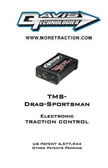
Transcription
CTION CONTROLUS PATENT 6,577,944Other Patents Pending
COPYRIGHT NOTICECopyright 1999-2013 Davis Technologies, LLC.All rights reserved.Information in this document is subject to changewithout notice. Other products and companiesreferred to herein are trademarks or registeredtrademarks of their respective companies or markholders. Any components shown are for illustrationor instructional purposes only.Publication and redistribution of this manual overthe Internet or in any other medium without priorwritten content is expressly forbidden. In all casesthis copyright notice must remain intact andunchanged.Davis Technologies, LLC.PO Box 8250Asheville, NC. 28787(828) 645-1505email: support@moretraction.comweb: www.MORETRACTION.comTRADEMARKSAll trademarks used herein are the property of theirrespective owners.RacePak is a registered trademark of CompetitionSystems, Inc.MSD is a registered trademark of AutotronicControls Corporation.07/13
Table of ContentsTable of Contents . 1Introduction . 3How Does It Work? . 4Installation . 6System Overview . 8Traction Control Adjustments . 9Retard Setup . 10Traction Control Setup . 12Trigger Count: . 12Starting RPM: . 12Buffer: . 12Sample Rate: . 12Configuring . 13Trigger Count: . 13Starting RPM: . 14Buffer: . 15Sample Rate: . 15Testing . 16Sensor test: . 16RPM Window Test: . 16Forced Activation Test: . 17Checking Settings:. 18Standard . 18Advanced . 19Factory Reset. 20Firmware Updating . 21Appendix A . 22Appendix B . 23Appendix C . 24Ring & Sensor . 25Traction Control Panel Software: . 27
Main Tab Settings: . 28Advanced Main Tab Settings: . 30More Tab Settings: . 32Starting RPM . 32End RPM . 32Triggers . 32More Tab Advanced Settings: . 34Null Tab Settings: . 36Step 1 & Step 2 Corrections (Null Mode 0): . 36Step 1 Corrections Only (Null Mode 1): . 36No Corrections (Null Mode 2): . 36Admin Tab: . 38USB to Serial Adapter: . 39Handheld Programmer . 40Disclaimer . 41Notes . 42Notes . 43Notes . 44Contact Information . 452Davis Technologies TMS-Drag-Sportsmanwww.moretraction.com
IntroductionWe would first like to thank you for your purchase ofour system. We believe it is the best systemavailable to you on the market today. This systembalances effectiveness with ease of installation,broad field of uses, and cost.As with all technical devices such as engines,shocks, carburetors, clutches etc., the product’sperformance is based largely on your ability to use itproperly. Testing in controlled circumstances willhelp you determine the proper settings for yourapplication and your situation. Testing is veryimportant since it will help you utilize this product toits full potential.Please read all of the instructions and informationthoroughly before attempting to install or use thisproduct.3Davis Technologies TMS-Drag-Sportsmanwww.moretraction.com
How Does It Work?The Non Self-Learning systems, like our Sportsmanseries, periodically compares the rate ofacceleration of the driveshaft to an Adjustable FixedRate (AFR), known as Threshold. If the DS RPM rateof change is in excess of that Threshold, then acorrection is made. The comparison is made every1/8 of a turn of the driveshaft.Basically, this Patented system looks for spikes inDS RPM that are caused by wheel slip. If thesespikes are large enough, then a correction is made,reducing the slip.By adjusting the Threshold, the user can tune thesystem to correct larger slips, while not reacting tosmaller, harmless, slips. This means the user doesnot have to figure out the desired DS/Engine RPMand build a preset “Dot Plot” (anybody got a crystalball?).A typical 1/8th mile car turns the drive shaft about300 times in a 660 ft. run. At 8 triggers per rev, thatwould be like building a “Dot Plot” w/ 2400 dots, and¼ mile cars turn the drive shaft about 550-600 timesin 1320 ft. run. At 8 triggers per rev, that would be4400-4800 dots.Self-Learning systems, such as our Lite and Prounits, compare the rate of acceleration of the driveshaft to a calculated threshold value that isconstantly updated based on the average of theprevious measurements. This update occurs onevery drive shaft revolution. So, if the last 1/8 of a4Davis Technologies TMS-Drag-Sportsmanwww.moretraction.com
turn of the drive shaft is faster than the average ofthe last full revolution, then a slip is detected.Through this very advanced Patented process, thesystem constantly accounts for track conditions, tirecondition, etc. to constantly update the internalsettings. These settings are updated as many as 800times a second to keep the unit calibrated to exactlythe right settings regardless of changing conditions.Basically, the system learns the average rate ofacceleration of the drive shaft, and if there is asudden spike in RPM above that learned rate, then acorrection is made. With the Self-Learning feature,the user doesn’t have to try to figure out the DS RPMrate of change and set a “Threshold”, the systemdoes it for you, every drive shaft revolution!The user does have an adjustment referred to as“Mode” that sets the overall sensitivity of the systemto make a correction based the extent of the tire slip.By adjusting the Mode, the user can tune the systemto correct larger slips, while not reacting to smaller,harmless, slips.This system is not simply a few lines of code addedto an existing fuel injection or ignition system, andcalled traction control.This system utilizes apatented method and multiple high speedprocessors to very accurately and effectivelymonitor rates of acceleration to determine wheelspeed, and tire slip. In fact, Davis Technologies’systems are at least 20 times faster than othersystems which are integrated into the fuel injectionor ignition system.Our systems only job is Traction Control!5Davis Technologies TMS-Drag-Sportsmanwww.moretraction.com
InstallationInstallation of the system is very simple. It is veryimportant to make all connections correctly.Improper installation could result in poor systemperformance or damage to the system.Keep all wires away from any spark plug wires andcoils or other sources of electrical noise and heat.The unit should be mounted away from any sourcesof electrical noise or high heat.Make the connections as follows:2 Pin Connector (Power In)1. Connect pin “A” (RED wire) to 12v Positive.2. Connect pin “B” (BLACK wire) to 12v Ground.3 Pin Connector (Sensor)1.Connect the pin marked “A” (RED wire) to thered wire on the sensor (12v positive)2.Connect the pin marked “B” (BLACK wire) tothe black wire on the sensor (ground).3.Connect the pin marked “C” (WHITE wire) tothe white wire on the sensor. This wiring is forsensors supplied by Davis Technologies.6Davis Technologies TMS-Drag-Sportsmanwww.moretraction.com
If another type of sensor is used, check with The sensor must be capable of 15Khzresolution!!)2 Pin Connector (Output)1.Connect Pin “A” (Pink wire) to the first retardstage of ignition system.2.Connect Pin “B” (Tan wire) to the secondretard stage of the ignition system. (Pro System Only)These leads will output 12 volt (Battery Voltage)when unit is making corrections. They arecumulative, meaning that a small correction will turnon the Pink wire and a large correction will turn onthe Pink and Tan wires.It is also very helpful to tie these connections into adata channel if available. That way the user can seewhat the Traction Control system did during a pass.This info is very useful for adjusting the setup.Consult with your data acquisition supplier. IMPORTANT-- IF THE TRACTION CONTROL ISCONNECTED TO A RETARD STAGE THAT IS ALSOCONNECTED TO A NITROUS SOLENOID, A DIODEMAY BE REQUIRED TO PREVENT THE TRACTIONCONTROL FROM INADVERTENTLY ACTIVATINGTHE SOLENOID.7Davis Technologies TMS-Drag-Sportsmanwww.moretraction.com
System OverviewIMPORTANT- MSD 8975 Digital Multi Retard (usesdials to set retard) is NOT compatible with DavisTechnologies Traction Control Systems.MSD 8973 3 Step Retarder (uses chips to setretard) may be used.8Davis Technologies TMS-Drag-Sportsmanwww.moretraction.com
Traction Control AdjustmentsDifferent tracks, cars, conditions, etc. may requiredifferent settings for the system to functioneffectively. The dials on the unit are used for thesesettings.The Drag-Sportsman incorporates a patentedmethod to control wheel spin where the users sets aThreshold of acceleration that if exceeded will causethe timing to retard.The sensitivity of the system is adjusted using theThreshold dial. The Threshold simply sets themaximum rate of acceleration allowed. If this rate isexceeded then a correction is made. The higher thenumber the more aggressive the system is. A goodstarting point is Threshold 3. If you feel that yoursystem is making too many corrections while set toThreshold 3, then try Threshold 2. Valid settingsfor Threshold are 1-8.(OFF turns unit off, except for sensor test / AUXactivateswindowRPMtest).9Davis Technologies TMS-Drag-Sportsmanwww.moretraction.com
Retard SetupThe TMS-Drag-Sportsman connects to the stepretard inputs of the ignition controller, sending it a12 volt signal to cause it to retard ignition timingwhen wheel slip is detected. You must configureyour controller to retard timing when the inputs aretriggered. A timing retard of 3-5 Degrees is a goodstarting point.Some digital ignition controllers are configurable toallow the timing to be ramped in and out. You neverwant to ramp the timing out, you must allow the TCto retard the timing as fast as possible when slip isdetected.10Davis Technologies TMS-Drag-Sportsmanwww.moretraction.com
Ramp Off is used to control how quickly the timingis ramped back in after the slip condition iscorrected. A Ramp Off setting of about 1/10th of asecond is a good starting point; with a longer rampin if more retard is used. If the amount of powerreduced during a slip condition is too great, then asmaller retard may be required. If the tires recoverfrom a slip condition and immediately slip again,then a longer RAMP Off may be desired.IMPORTANT- Most MSD programmable controllershave a setting called Step Delay that holds the retardfor an amount of time after the 12 volt trigger fromthe TC has been removed. This setting is usuallydefaulted to .5 – 2.0 sec. This MUST be set to 0.0sec, or the system will not work correctly, and thecar will slow down!(The image above is from MSD GraphView Software)11Davis Technologies TMS-Drag-Sportsmanwww.moretraction.com
Traction Control SetupTrigger Count:The unit must be configured for the number of counts itwill receive per revolution of the driveline.Starting RPM: is a user adjustable setting that allowsthe racer to set the point at which the unit begins makingcorrections. If the Starting RPM is set to 1800 RPM, thenthe unit is active and monitoring the driveline, but notmaking any corrections until the Starting RPM is reached.This may be useful to prevent the Traction Control frominterfering with an already established launch setup.The following parameters are adjustable; however theyare factory set to the most common settings, and shouldnot need to be adjusted by most users.Buffer: is another setting that can be used to finetune the system. The buffer sets the number ofconsecutive errors required to cause a correction.Buffer 0 will react to each error in acceleration.Buffer 1 will require at least 2 consecutive slipconditions to cause a correction. This is useful tofilter out small tire slips that may occur quickly, buthave no ill effect on the car. (Buffer 1 is the default formost applications, but some experimenting with thissetting may be useful to see what works best for you).Sample Rate: of the unit can also be changed bythe user, however this should only be done afterconsulting w/ tech support. The lower the numberthe faster the Sample Rate, which makes the unitless sensitive, but faster to react. The higher thenumber the slower the Sample Rate, which makesthe unit more sensitive, but slower to react. Validsettings are 1-5. (Default 3)12Davis Technologies TMS-Drag-Sportsmanwww.moretraction.com
ConfiguringTrigger Count:(default 8)The unit must be configured for the number ofcounts it will receive per revolution of the driveline.Once set the value will remain until changed by theuser. To change the value, follow these steps.1.Set the “Mode” dial to “4”2.Hold down the “Test” button3.Turn the power On4.While holding the “Test” button down, movethe “Mode” dial to the desired number of triggersdivided by two.(example- 8 triggers/2 4)5.Release the “Test” button.The LED will flash to show the number of triggersthe unit is now set to. (The Trigger Count must beset correctly for the accurate RPM calculations)13Davis Technologies TMS-Drag-Sportsmanwww.moretraction.com
Starting RPM: (default (15 ) 1500 Rpm)The driveline RPM at which the unit Starts to makecorrections can be set by the user. Once set thevalue will remain until changed by the user. TheRPM is set in 100 rpm increments, (example 1500rpm, divided by 100 15). To change the StartingRPM value, follow these steps.1.Set the “Mode” dial to “3”2.Hold down the “Test” button3.Turn the power On4.While holding the “Test” button down, movethe “Mode” dial to the first digit of the desiredStarting RPM.(example- 1500rpm - first digit 1 / 3000rpm - first digit 3)5.Release the “Test” button,The led will flash to show the value has beenaccepted.6.Now move the “Mode” dial to the second digitof the desired Starting RPM, then press and releasethe “Test” button. (example- 1500rpm - sec. digit 5 / 3000rpm sec. digit 0)The led will flash to show the value has beenaccepted.After about 1 second the LED will Blink to show thevalue that the Starting RPM is set to. The first digitis output followed by a short pause, then the seconddigit is output. (1500 RPM 1,5 Blinks) (zeros areindicated by shorter blinks)14Davis Technologies TMS-Drag-Sportsmanwww.moretraction.com
Buffer:(default 1)A buffer can be set to lower the sensitivity of the unitif desired. To change the value, follow these steps.1.Set the “Mode” dial to “1”2.Hold down the “Test” button3.Turn the power On4.While holding the “Test” button down, movethe dial to the desired buffer value.5.Release the “Test” button,The led will flash to show the value that the buffer isnow set to. Valid settings are 0-3. (Buffer 2 2 blinks)(zeros are indicated by shorter blinks)Sample Rate:(default 3)The Sample Rate can be set to change the sensitivityof the unit. This should only be changed under theadvice of tech support. Valid settings are 1-5. Tochange the value, follow these steps.1.Set the “Mode” dial to “2”2.Hold down the “Test” button3.Turn the power On4.While holding the “Test” button down, movethe dial to the desired Sample Rate value.5.Release the “Test” button,The LED will flash to show the value that the SampleRate is now set to. Valid settings are 1-5.(Most usersnever need to adjust the Sample Rate)15Davis Technologies TMS-Drag-Sportsmanwww.moretraction.com
TestingAfter installation it is recommended that you test thesystem. To do so please follow these instructionsstep by step. (Temporarily set the “% Cut” dial to100 and “Ramp In” dial to 9 for testing)Sensor test:This test is useful for setting up the trigger ring andsensor if used.1.Set the “Mode” dial to “OFF”2.Rotate the RPM trigger-The LED will flash each time a trigger is sensed.The unit is not active in any other way and nocorrections will be made. The LED will appear toglow if triggered quickly. (The data output will alsotrigger)RPM Window Test:This mode is useful to check that the system isreading the RPM signal correctly.1.Set the “Mode” dial to “AUX”2.Start the engine and accelerate the driveline.3.When the driveline RPM is within the windowof 1000 to 3000 rpm the LED will glow solidand the unit will make a large correction.16Davis Technologies TMS-Drag-Sportsmanwww.moretraction.com
Forced Activation Test:This test is useful to check both stages of cut. Theignition system must be configured prior toexecuting this test.This is also useful to test the connections to a datasystem if used.1.Set the dial to any setting between 1 to 7.2.Connect a timing light to the engine3.Turn “on” the power to the unit, the LEDshould begin to flash.4.Start the engine.5.With the engine idled up to about 3500 rpm;press the Test button on the unit until the LEDglows solid. The first correction level willactivate for 4 seconds, then the second stagefor the next 4 seconds.(The engine only needs to be running to check ignition timing,outputs will trigger with engine off.)Note: After the test is complete, the LED will blink toshow the firmware version.If unit does not pass all tests, recheck all setupparameters and connections and retest.17Davis Technologies TMS-Drag-Sportsmanwww.moretraction.com
Checking Settings:The current setting for the different adjustments canbe verified at any time using the Test button and theLED.This process is divided into 3 sections.Standard, Advanced and Null Zone. The differentsections are chosen by the position by the dial whenthe verification is started.Standard values can be verified at any time byfollowing these steps.1.Turn the power “On”2.Set “Mode” dial any position from 1-7.3.Press the “Test” button and HOLDDOWN.4.The LED will glow solid for 8seconds (as in the Forced Activation Test),then blink to show the firmware version.5.Next the LED will flash the value for theBuffer. (A setting of zero is indicated by ashort blip of the LED).6.After a short pause, the Led will flash for thevalue of Sample Rate, followed by a pause.8.Lastly, the LED will Flash the current SelfLearning status value. (for tech supportpurposes only).18Davis Technologies TMS-Drag-Sportsmanwww.moretraction.com
Advanced values can be verified at any time byfollowing these steps.1.Turn the power “On”2.Set “Mode” dial to “OFF”.3.Press the “Test” button and HOLDDOWN.4.First, the value of the Starting RPM isshown. The LED will blink for the first digitfollowed by a short pause, then the LED willblink for the second digit.(1500 RPM 1,5Blinks) (zeros are indicated by shorterblinks).5.After a pause, The value for the EndingRPM is shown. The LED will blink for thefirst digit followed by a short pause, thenthe LED will blink for the second digit.(8500RPM 8,5 Blinks) (zeros are indicated byshorter blinks).6.After a short pause, the LED will flash for thevalue of Trigger Count. (8 Triggers 8 Blinks).19Davis Technologies TMS-Drag-Sportsmanwww.moretraction.com
Factory ResetAll TC settings can be restored to Factory Defaultsat any time by following these steps.1.Set the dial to “5”2.Hold down the “Test” button3.Turn the power On4.While holding the “Test” button down, movethe dial to the “Off“ position.5.Release the “Test” button,The LED will flash rapidly to indicate the FactorySettings have been restored.20Davis Technologies TMS-Drag-Sportsmanwww.moretraction.com
Firmware UpdatingDavis Technologies, LLC may release firmwareupdates or upgrades periodically to ensure the bestpossible functionality of the Traction ControlSystem. The traction control unit will need to bereturned to Davis Technologies to have the updatesinstalled and configured.Users should log onto www.moretraction.com, orcall Davis Technologies, LLC tech departmentoccasionally to check for updates.21Davis Technologies TMS-Drag-Sportsmanwww.moretraction.com
Appendix A22Davis Technologies TMS-Drag-Sportsmanwww.moretraction.com
Appendix BThe biggest difference in our systems is the Speedand the Self-Learning capabilities. Other systems“brag” that their TC works 10 times a second—ourolder systems worked 20 times a second, and whileit would help “save a run”, it just was not fastenough to help you go faster.The new systems (since Jan 2009) work every 1/8thof a turn of the driveshaft. At 3000 RPM DS speed, avery critical area for tire slip, it measures the DSRPM 400 times a second, at 6000 DS RPM itmeasures 800 times a second! The system thenprocesses those measurements 50 times a second(typically), and as fast as 100 times a second, tocalculate acceleration change (DS RPM Delta). (Wecan actually use up to 30 triggers, which would be1500 times a second at 3000 DS RPM, and 3000times a second at 6000 DS RPM !!)Our units utilize 2 high speed processors tomeasure and calculate drive shaft data, and nothingelse. Our patented systems are not simply a fewlines of code thrown into an existing enginemanagement system and called traction control.This is all we do, and all we have done for the past14 years! Traction Control Is What We Do!23Davis Technologies TMS-Drag-Sportsmanwww.moretraction.com
Appendix CRacePak Sensor Pin Out24Davis Technologies TMS-Drag-Sportsmanwww.moretraction.com
Ring & Sensor25Davis Technologies TMS-Drag-Sportsmanwww.moretraction.com
This Page Left Blank26Davis Technologies TMS-Drag-Sportsmanwww.moretraction.com
Traction Control PanelSoftware:(Drag Pro Systems Only)The Traction Control Panel (TCP) software interfaceis used to adjust advanced tuning features of thetraction control system.These tuning features can be used to fine tune thesystem to exactly what the user desires.On drag racing systems, this includes being able totune the drive shaft RPM at which the systembecomes active, as well as the RPM at which thesystem can be deactivated.The user can also tune the length of corrections, andthe amount of power that is cut on different parts ofthe race track.The software based interface is easily downloadedfrom the web site and installed on your computer.The Traction Control is connected to the computervia a serial cable or through a secure wirelessBluetooth connection. Tuning is achieved througha few simple mouse clicks.27Davis Technologies TMS-Drag-Sportsmanwww.moretraction.com
Main Tab Settings:The Self Learning units incorporate two differentmethods to control wheel spin.The second patented method is a less advancedprocess where the users sets a threshold ofacceleration that if exceeded will cause the timing toretard.The second- Non-Self Learning system is activatedwhen the “Threshold” setting is set to anythingother than zero. The Non-Self Learning Method isonly accessible using the “Traction Control PanelSoftware”.Threshold is used to set this value. The higher thenumber the more sensitive the system is. A goodstarting point is 4. Valid settings for threshold are 19.Mode is used to adjust the Mode of the unit usingthe software instead of the button on the unit asdescribed earlier in this manual.Note: To use the Mode and Threshold sliders in thesoftware, you must check the “Set Dials Here” box.When checked, the TC unit only uses the TCPsettings, and the setting cannot be changed usingthe button on the unit. To use the button method,YOU MUST UN-CHECK THIS BOX!28Davis Technologies TMS-Drag-Sportsmanwww.moretraction.com
Main Tab- Basic Screen29Davis Technologies TMS-Drag-Sportsmanwww.moretraction.com
Advanced Main Tab Settings:These settings should only be adjusted if advised todo so by Davis Technologies!The Buffer setting is another feature that can beused to fine tune the system. The buffer sets thenumber of consecutive slip conditions required tocause a correction. Buffer 0 will react to each slipcondition.Buffer 1 will require at least 2consecutive slip conditions to cause a correction.This is useful to filter out small tire slips that mayoccur quickly, but have no ill effect on the car.(Buffer 1 is the default for most applications, but someexperimenting with this setting may be useful to seewhat works best for you).The Frequency of the unit can also be changed bythe user, however this should only be done afterconsulting w/ tech support. The lower the numberthe faster the Sample Rate, which makes the unitless sensitive, but faster to react. The higher thenumber the slower the Sample Rate, which makesthe unit more sensitive, but slower to react. Validsettings are 1-5. (Default 3 Dirt / 4 Asphalt)30Davis Technologies TMS-Drag-Sportsmanwww.moretraction.com
Main Tab- Advanced Screen31Davis Technologies TMS-Drag-Sportsmanwww.moretraction.com
More Tab Settings:The More Tab allows the user to set the StartingRPM, Triggers, as well as some Advanced RPMcontrols.Starting RPM is a user adjustable setting thatallows the racer to set the point at which the unitbegins making corrections. If the Starting RPM isset to 1500 RPM, then the unit is active andmonitoring the driveshaft speed, but not making anycorrections until the Starting RPM is reached. Oncethe Starting RPM is reached, the unit will makecorrections as needed, until the End RPM isreached.End RPM is a user adjustable setting that allowsthe racer to set the point at which the unit stopsmaking corrections. Once the End RPM is reached,the unit will stop making corrections.Triggers is a user adjustable setting that allowsthe racer to set the number of triggers the TC ispicking up for each revolution of the measuredshaft. In most cases, this is the number of triggerson the driveshaft collar.32Davis Technologies TMS-Drag-Sportsmanwww.moretraction.com
More Tab- Basic Screen33Davis Technologies TMS-Drag-Sportsmanwww.moretraction.com
More Tab Advanced Settings:The Advanced Screen of the More tab allows theuser to tune the minimum number of driveshaftrotations that the timing will be retarded during acorrection. This is useful to force the timing to stayretarded long enough to stop a high momentumspin, even though the RPM spike was very brief.34Davis Technologies TMS-Drag-Sportsmanwww.moretraction.com
More Tab- Advanced Screen35Davis Technologies TMS-Drag-Sportsmanwww.moretraction.com
Null Tab Settings:The Null zone is used to adjust how much timing, ifany, is retarded on different parts of the track.These ranges are based shaft RPM.Step 1 & Step 2 Corrections (Null Mode0): is used to allow the unit to make either correctionin the RPM window set by the Null Low RPM andNull High RPM values. This is the same behavior asoutside the RPN window, and is used to essentiallydeactivate the null zone without having to reset theRPM values. (This is useful when setting up the NullZone with the knobs on the unit if the software is notavailable. See “Traction Control Setup” above)Step 1 Corrections Only(Null Mode 1):is used to force the unit to only make small timingcorrection in the RPM window set by the Null LowRPM and Null High RPM values.No Corrections(Null Mode 2):is used toforce the unit to make no timing correction in theRPM window set by the Null Low RPM and Null HighRPM values.36Davis Technologies TMS-Drag-Sportsmanwww.moretraction.com
Null Tab Screen37Davis Technologies TMS-Drag-Sportsmanwww.moretraction.com
Admin Tab:The Admin screen is used to provide informationabout the unit for tech support by DavisTechnologies.38Davis Technologies TMS-Drag-Sportsmanwww.moretraction.com
USB to Serial Adapter:Newer laptop computer may not have an actualRS232 DB9 connector installed. In this case a USBto Serial adapter will be required. Not all adaptersare created equally, and some brands may not workproperly with the Tra
The TMS-Drag-Sportsman connects to the step retard inputs of the ignition controller, sending it a 12 volt signal to cause it to retard ignition timing when wheel slip is detected. You must configure your controller to retard timing when the input




![Unreal Engine 4 Tutorial Blueprint Tutorial [1] Basic .](/img/5/ue4-blueprints-tutorial-2018.jpg)
