Transcription
Switching Mode Power SupplyZEN-PA03024Please read and understand this catalog before purchasing the products. Please consult your OMRON representative if your have any questions or comments. Refer to Warranty and Application Considerations(page 8), and Safety Precautions (page 6)New Compact Power Supply (30 W) for ZENProgrammable Relays Slim size with a depth of 56 mm (W H D: 70 90 56 mm). EMI: Conforms to EN61000-6-3 (Class B). Allows parallel operation. Output voltage: 24 VDC; Output current: 1.3 A; Capacity: 30 W Safety standards: UL508/60950/1604,CSA C22.2 No. 14/60950/213,EN60950(VDE0806), EN50178(VDE0160) Uses lead-free soldering. Six-language instruction manual provided.Model Number Structure Model Number LegendZEN-PA 030 241231. UnitPA: Power supply unit2. Power Ratings030: 30 W3. Output voltage24: 24 VOrdering Information List of ModelsPower ratings30 WInput voltage100 to 240 VACOutput voltage24 VDCOutput current1.3 AModel numberZEN-PA03024 Accessories (Order Separately)NameMounting Track50 cm (l) 7.3 mm (t)ModelsPFP-50N1 m (l) 7.3 mm (t)PFP-100N1 m (l) 16 mm (t)PFP-100N2End PlatePFP-MSpacerPFP-SSwitching Mode Power SupplyZEN-PA030241
Specifications Ratings/CharacteristicsEfficiency (typical)80% min.Input100 to 240 VAC (85 to 264 VAC),95 to 350 VDC (See note 1.)VoltageFrequencyCurrentLeakage currentOutput50/60 Hz (47 to 450 Hz)100 VAC input0.8 A max.200 VAC input0.45 A max.100 VAC input0.4 mA max.200 VAC input0.75 mA max.Inrush current (See note 2.) 100 VAC input25 A max.200 VAC input50 A max.Voltage adjustment range (See note 3.)-10 to 15% (with V.ADJ) of rated output voltageRipple2% (p-p) max. (-25 to -10 C: 4% max.)Input variation influence0.5% max.Load variation influence (rated input voltage) 1.5% max.Temperature variation influence0.05%/ C max.Start up time (See note 2.)1,000 ms max. (100 VAC or 200 VAC, at rated output voltage)Hold time (See note 2.)15 ms min., 20 ms (typical) (100 VAC or 200 VAC, at rated output voltage)AdditionalfunctionsOverload protection (See note 2.)105% to 135% of rated load current, inverted L drop, intermittent, automatic resetParallel operationYes (2 units max. For details, refer to the derating curve in Engineering Data. For DCinput, parallel operation is possible only for 110 to 350 VDC.)Series operationNoOthersAmbient temperatureOperating: Refer to the derating curve in Engineering Data. (with no icing or condensation)Storage: -25 to 75 C (with no icing or condensation)Ambient humidityOperating: 10 to 90%Storage: 10 to 90%Mounting methodDIN track mounting, surface mountingDielectric strength2.0 kVAC for 1 min. (between all inputs and exposed non-current-carrying metal parts;detection current: 10 mA max.)3.0 kVAC for 1 min. (between all inputs and all outputs; detection current: 20 mA max.)1.0 kVAC for 1 min. (between all outputs and non-current-carrying metal parts;detection current: 10 mA max.)Insulation resistance100 MW min. (between all outputs and all inputs/exposed non-current-carrying metalparts) at 500 VDCVibration resistance10 to 55 Hz, 0.375-mm single amplitude for 2 h each in X, Y, and Z directionShock resistance300 m/s2, 3 times each in X, Y, Z directionsOutput indicatorEMIYes (color: green)ConductedemissionsConforms to EN61000-6-3 (Class B)RadiatedemissionsConforms to EN61000-6-3 (Class B)Approved standardsUL: UL508 Listing Class 2, 60950, 1604 (Class I/Division 2)cUL: CSA C22.2 No. 14 Class 2, No. 60950, No. 213 (Class I/Division 2)EN/VDE: EN60950 ( VDE0805), EN50178 ( VDE0160)Conforms to VDE0106/P100 (Finger protection)Weight240 g max.Note: 1. This product has been approved for safety standards only when an AC input is used. It has not been approved when a DC input is used.2. Refer to the Engineering Data section on page 4 for details.3. If the V. ADJ adjuster is turned, the voltage will increase by more than 15% of the voltage adjustment range.Check the output voltage of the power supply when converting the output voltage, and make sure that the load will not be damaged.2Switching Mode Power Supply ZEN-PA03024
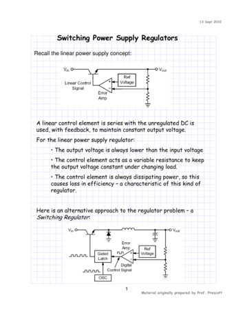
Connections Block DiagramZEN-PA03024Fuse 2A VL1INPUTDC OUTPUTNoise filter VL2/NRectifier/Inrush currentprotection circuit smoothingcircuitRectifier/smoothingcircuitDrive controlcircuitOvercurrentcircuitCurrentdetection circuitOvervoltagedetection circuitPhotocouplerNote: The Power Supply is provided with reinforced insulation between the input and output terminals. InstallationNo.NameFunction1AC input terminal (L1)2AC input terminal (L2/N) Connect the input line to this terminal. Negative pole for DC input.3DC output terminals ( V) Connect the load lines to these terminals.4DC output terminals (-V) Connect the load lines to these terminals.5Output indicator(DC ON: Green)6Output voltage adjuster Use to adjust the voltage.(V.ADJ)Switching Mode Power SupplyConnect the input line to this terminal. A fuse is included in the circuit.Lights while a direct current (DC)output is ON.ZEN-PA030243
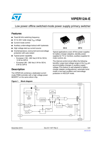
Engineering Data Derating Curve Overload ProtectionLoad (%)85 to 264 VAC or 110 to 350 VDC input120(1)100The Power Supply is provided with an overload protection functionthat protects the load and the power supply from possible damage byovercurrent. When the output current rises above 105% min. of therated current, the protection function is triggered, decreasing the output voltage. When the output current falls within the rated range, theoverload protection function is automatically cleared.(Reference value)For paralleloperation(See note 1.)6040Output voltage (V)80(2)200 30 20 10 25020 30 40 50 6045 55Ambient Temperature ( C)10Load (%)95 to 110 VDC inputIntermittent operation120050100100Output current (%)The values shown in the above diagrams are for reference only.(1)80Note: 1. Internal parts may occasionally deteriorate or be damagedif a short-circuited or overcurrent state continues during operation.2. Internal parts may possibly deteriorate or be damaged if thePower Supply is used for applications with frequent inrushcurrent or overloading at the load end. Do not use the PowerSupply for such applications.6040(2)200 30 20 10 2501020 30 40 50 6055Ambient Temperature ( C)Note: 1. The maximum ambient temperature for parallel operation is45 C.2. Parallel operation is not possible for an input of 95 to110 VDC.3. Although operation is possible in the (2) portion of the derating curve, performance may be adversely affected, i.e.,ripple noise may increase.4. Internal parts may occasionally deteriorate or be damaged.Do not use the Power Supply in areas outside the deratingcurve (i.e., the area shown by shading (1) in the abovegraph). Inrush Current, Start Up Time,Hold TimeInput OFFInput ONAC inputvoltageInrush current on input applicationAC tputvoltageStart up time (1,000 ms max.)Hold time (15 ms min.)Standard mountingFace-up mountingNote: 1. Improper mounting will interfere with heat dissipation andmay occasionally result in deterioration or damage of internal parts. Use the standard mounting.2. If there is a derating problem, use forced air-cooling. Theambient temperature is specified for a point 50 mm belowthe Power Supply.4Switching Mode Power Supply ZEN-PA03024
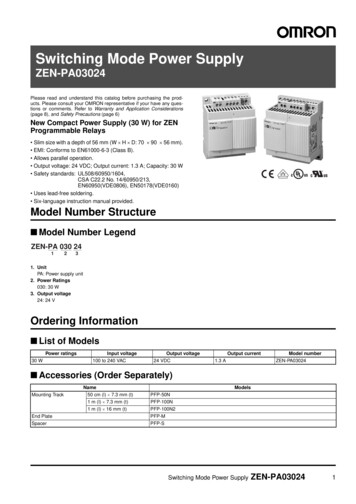
DimensionsNote: All units are in millimeters unless otherwise indicated.ZEN-PA03024Surface Mounting HolesTwo, M490458080604.7(Sliding: 13 max.)60447056 Accessories (Order Separately)Mounting TrackPFP-100N, PFP-50NPFP-100N2167.3 0.154.54.515 252510251,000 (500)(See note.)1035 0.327 0.1535 0.325 *1512525 152525101,000272411029.21.5Note: The values shown in parentheses are for the PFP-50N.End PlatePFP-M106.2SpacerPFP-S161251.81501.811.535.5 35.334.844.31.310 M4 x 8pan headscrew4.816.5Switching Mode Power SupplyZEN-PA030245
Safety PrecautionsWiring!CAUTIONMinor electric shock may occasionally occur. Do not disassemblethe product or touch internal parts.Minor fires may occasionally occur. Do not attempt to repair ormodify the product.Minor burns may occasionally occur. Do not touch the productwhile power is being supplied or immediately after power isturned OFF.Minor fires may occasionally occur. Tighten terminal screws to atorque of 0.5 to 0.6 N·m so that they do not become loose.Minor electric shock may occasionally occur during operation. Donot touch the input and output terminals while power is beingsupplied.The product may occasionally be damaged. Do not allow anyclippings or cuttings to enter the product during installation work.Working voltage can be 350 V max. inside. This voltage can bealso available 10 s after the switch off. Precautions for Safe UseThe following precautions must be observed to ensure safety.Mounting Mounting Direction(Refer to Installation in Engineering Data on page 4.)Standard Mounting Minor fire may possibly occur. Ensure that input and outputterminals are wired correctly. Use the following material for the wires to be connected to thePower Supply to prevent smoking or ignition caused by abnormalloads.Use solid wires. Always attach pin crimp terminals when usingstranded wire. The stripping distance should be 6.5 mm.Recommended Wire TypeSolid wireCross section 0.5 to 2.5 mm2(Equivalent to AWG20 to AWG14)Stranded wireCross section 0.5 to 2.5 mm2(Equivalent to AWG20 to AWG14)Pin crimp terminalsDia.: 1.1 to 2.3 mm Do not apply more than 100 N force to the terminal block whentightening the terminals. Be sure to remove the sheet covering the product before turningON the Power Supply and confirm that nothing is interfering withheat dissipation.Installation Environment Do not use the Power Supply in locations subject to shocks orvibrations. In particular, install the Power Supply as far away aspossible from contactors or other devices that are a vibrationsource. Install the Power Supply well away from any sources of strong,high-frequency noise.ValidHorizontal MountingInvalidOther MountingInvalidOperating and Storage ConditionsThe internal parts may occasionally deteriorate or be broken due toadverse heat dissipation depending on the mounting status. Do notuse the product in any way other than the standard mountingdirection. Mounting SpaceMake sure that sufficient heat dissipation is provided wheninstalling the Power Supply to increase its long-term reliability.Install the product in a location that allows a natural airflow to occuraround the Power Supply.We recommend using End Plates (PFP-M) to secure the PowerSupply and to ensure that a space of at least 10 mm is maintainedbetween Power Supplies.If the installation space above and below the Power Supply is lessthan 50 mm, reduce the ambient temperature by 5 C. A minimumspace of 20 mm is required.ZEN-PA03024(See note 2.)(See note 1.) When installing the Power Supply, check for any signs that theproduct or packaging has been struck. If internal parts have beendamaged, overvoltages may be output depending on the location ofthe damage. Internal parts may occasionally deteriorate or be damaged. Storethe Power Supply at a temperature of -25 to 65 C and a humidity of10% to 90%. Internal parts may occasionally deteriorate or be damaged. Do notuse the Power Supply in areas outside the derating curve (i.e., thearea shown by shading (1) in the graph on page 4). For UL508Listing, the surrounding air temperature should be 40 C. Use the Power Supply at a humidity of 10% to 90%. Do not use the Power Supply in locations where condensation mayoccur due to high humidity or where temperature changes aresevere. Do not use the Power Supply in locations subject to direct sunlight. Do not use the Power Supply in locations where liquids, foreignmatter, or corrosive gases may enter the interior of products.Overload Protection Internal parts may possibly deteriorate or be damaged if a shortcircuited or overcurrent state continues during operation. Internal parts may possibly deteriorate or be damaged if the PowerSupply is used for applications with frequent inrush current oroverloading at the load end. Do not use the Power Supply for suchapplications.Charging the Battery(See note 3.)(See note 2.)(See note 1.)Note: 1. Convection of air2. 50 mm min.3. 10 mm min.6 This product is not intended to function as a battery charger. If abattery is to be connected as the load, mount an overcurrentlimiting circuit and an overvoltage protection circuit.Switching Mode Power Supply ZEN-PA03024
Output Voltage AdjusterUse the following guidelines to select the diode. The output voltage adjuster (V.ADJ) may possibly be damaged if itis turned with unnecessary force. Do not turn the adjuster withexcessive force. After changing the setting of the adjuster, make sure that the outputcapacity and output current do not exceed the rated output capacityand rated output current. Output voltage is adjustable with the output voltage adjuster(V.ADJ) on the front surface of the product from -10% to 15% ofthe rated output voltage.Do not increase the output voltage by more than 10% whenconnected to a ZEN CPU Unit rated for 24 VDC.TypeTwice the rated outputvoltage or aboveForward current (IF)Twice the rated outputvoltage or aboveParallel OperationTwo Power Supplies can be operated in parallel.CorrectDIN Track MountingSchottky Barrier diodeDielectric strength (VRRM)ZEN-PA03024AC (L1) VAC (L2/N)To mount the Power Supply on a DIN track, hook portion (A) of thePower Supply onto the track and press the Power Supply in direction(B). VAC (L1) VAC (L2/N) V(A)ZEN-PA03024(B)To dismount the Power Supply, pull down portion (C) with a flat-bladescrewdriver and pull out the Power Supply.Note: 1. For parallel operation, a maximum of two Power Supplies ofthe same model can be connected.2. For a DC input, parallel operation is possible only for 110 to350 VDC.3. To ensure that the voltage drop between each Power Supplyand the load is the same, use the same wire length andthickness to connect the load.4. The load current will become imbalanced if the outputvoltages are different, possibly causing a serious reductionin the life of one of the Power Supplies. Adjust the outputvoltages of the Power Supplies to the same value.In Case there is No Output Voltage30 mm min.(C)The possible cause for no output voltage may be the presence of anoverload or overvoltage condition, or may be due to the functioning ofa latching protective device. The latching protection may operate if alarge amount of surge voltage such as a lightening surge occurswhile turning ON the Power Supply.Track stopperSeries OperationThe Power Supply is not designed for series operation.In case there is no output voltage, please check the following pointsbefore contacting us:IncorrectZEN-PA03024AC (L1) VAC (L2/N) VAC (L1) VAC (L2/N) V Check the overload protected status:Check whether the load is in overload status or is short-circuited.Remove wires to load when checking. Attempt to clear the latching protection function:Turn the power supply OFF once, and leave it OFF for at least 1minute. Then turn it on again to see if this clears the condition.Insulation Resistance TestZEN-PA03024When performing the test, be sure to short-circuit all the outputterminals to protect them from damage.Output voltage ( )Two Power Supplies can be used to create a output.CorrectDielectric Strength TestZEN-PA03024AC (L1) VAC (L2/N) VAC (L1) VAC (L2/N) VZEN-PA03024Note: When the load is an operational amplifier or other deviceallowing series operation, a startup failure may occur when thePower Supply is turned ON and internal circuits may bedamaged. Connect a diode as shown in the figure to preventthis. When a high voltage is applied between the input terminals and theoutput terminals, electric energy builds up across the inductor Land capacitor C of the internal noise filter. This energy maygenerate a voltage surge when a high voltage is applied to thePower Supply by a switch or timer, and as a result, the internalparts of the Power Supply may possibly be damaged. To preventvoltage impulses when testing, decrease the applied voltage usingthe variable resistor on the dielectric strength testing equipment, orapply the voltage so that it crosses the zero point when it rises orfalls. When performing the test, be sure to short-circuit all the outputterminals to protect them from damage.Switching Mode Power SupplyZEN-PA030247
Warranty and Application ConsiderationsWarranty and Limitations of LiabilityWARRANTYOMRON's exclusive warranty is that the products are free from defects in materials and workmanship for a period of one year (orother period if specified) from date of sale by OMRON.OMRON MAKES NO WARRANTY OR REPRESENTATION, EXPRESS OR IMPLIED, REGARDING NON-INFRINGEMENT,MERCHANTABILITY, OR FITNESS FOR PARTICULAR PURPOSE OF THE PRODUCTS. ANY BUYER OR USERACKNOWLEDGES THAT THE BUYER OR USER ALONE HAS DETERMINED THAT THE PRODUCTS WILL SUITABLY MEETTHE REQUIREMENTS OF THEIR INTENDED USE. OMRON DISCLAIMS ALL OTHER WARRANTIES, EXPRESS ORIMPLIED.LIMITATIONS OF LIABILITYOMRON SHALL NOT BE RESPONSIBLE FOR SPECIAL, INDIRECT, OR CONSEQUENTIAL DAMAGES, LOSS OF PROFITS,OR COMMERCIAL LOSS IN ANY WAY CONNECTED WITH THE PRODUCTS, WHETHER SUCH CLAIM IS BASED ONCONTRACT, WARRANTY, NEGLIGENCE, OR STRICT LIABILITY.In no event shall the responsibility of OMRON for any act exceed the individual price of the product on which liability is asserted.IN NO EVENT SHALL OMRON BE RESPONSIBLE FOR WARRANTY, REPAIR, OR OTHER CLAIMS REGARDING THEPRODUCTS UNLESS OMRON'S ANALYSIS CONFIRMS THAT THE PRODUCTS WERE PROPERLY HANDLED, STORED,INSTALLED, AND MAINTAINED AND NOT SUBJECT TO CONTAMINATION, ABUSE, MISUSE, OR INAPPROPRIATEMODIFICATION OR REPAIR.Application ConsiderationsSUITABILITY FOR USEOMRON shall not be responsible for conformity with any standards, codes, or regulations that apply to the combination ofproducts in the customer's application or use of the products.Take all necessary steps to determine the suitability of the product for the systems, machines, and equipment with which it willbe used.Know and observe all prohibitions of use applicable to this product.NEVER USE THE PRODUCTS FOR AN APPLICATION INVOLVING SERIOUS RISK TO LIFE OR PROPERTY WITHOUTENSURING THAT THE SYSTEM AS A WHOLE HAS BEEN DESIGNED TO ADDRESS THE RISKS, AND THAT THE OMRONPRODUCTS ARE PROPERLY RATED AND INSTALLED FOR THE INTENDED USE WITHIN THE OVERALL EQUIPMENT ORSYSTEM.DisclaimersCHANGE IN SPECIFICATIONSProduct specifications and accessories may be changed at any time based on improvements and other reasons. Consult withyour OMRON representative at any time to confirm actual specifications of purchased product.DIMENSIONS AND WEIGHTSDimensions and weights are nominal and are not to be used for manufacturing purposes, even when tolerances are shown.ALL DIMENSIONS SHOWN ARE IN MILLIMETERS.To convert millimeters into inches, multiply by 0.03937. To convert grams into ounces, multiply by 0.03527.Cat. No. L103-E1-01In the interest of product improvement, specifications are subject to change without notice.OMRON CorporationIndustrial Automation CompanyIndustrial Devices and Components Division H.Q.Industrial Control Components DepartmentShiokoji Horikawa, Shimogyo-ku,Kyoto, 600-8530 JapanTel: (81)75-344-7119/Fax: (81)75-344-71498Printed in Japan0903-3M (0903) (O)
Switching Mode Power Supply ZEN-PA03024 1 Switching Mode Power Supply . Do not attempt to repair or modify the product. Minor burns may occasionally occur. Do not touch the product . between Power