Transcription
Model 1685B, 1687B, 1688BSwitching DC Power SupplyINSTRUCTION MANUAL
1Safety SummaryThe following safety precautions apply to both operating and maintenance personnel andmust be observed during all phases of operation, service, and repair of this instrument. Beforeapplying power, follow the installation instructions and become familiar with the operatinginstructions for this instrument.GROUND THE INSTRUMENTTo minimize shock hazard, the instrument chassis and cabinet must be connected toan electrical ground. This instrument is grounded through the ground conductor ofthe supplied, three-conductor ac power cable. The power cable must be pluggedinto an approved three-conductor electrical outlet. Do not alter the groundconnection. Without the protective ground connection, all accessible conductiveparts (including control knobs) can render an electric shock. The power jack andmating plug of the power cable meet IEC safety standards.DO NOT OPERATE IN AN EXPLOSIVE ATMOSPHEREDo not operate the instrument in the presence of flammable gases or fumes.Operation of any electrical instrument in such an environment constitutes a definitesafety hazard.KEEP AWAY FROM LIVE CIRCUITSInstrument covers must not be removed by operating personnel. Componentreplacement and internal adjustments must be made by qualified maintenancepersonnel. Disconnect the power cord before removing the instrument covers andreplacing components. Under certain conditions, even with the power cableremoved, dangerous voltages may exist. To avoid injuries, always disconnect powerand discharge circuits before touching them.DO NOT SERVICE OR ADJUST ALONEDo not attempt any internal service or adjustment unless another person, capable ofrendering first aid and resuscitation, is present.DO NOT SUBSTITUTE PARTS OR MODIFY THE INSTRUMENTDo not install substitute parts or perform any unauthorized modifications to thisinstrument. Return the instrument to B&K Precision for service and repair to ensurethat safety features are maintained.1
WARNINGS AND CAUTIONSWARNING and CAUTION statements, such as the following examples, denote ahazard and appear throughout this manual. Follow all instructions contained inthese statements.A WARNING statement calls attention to an operating procedure, practice, orcondition, which, if not followed correctly, could result in injury or death topersonnel.A CAUTION statement calls attention to an operating procedure, practice, orcondition, which, if not followed correctly, could result in damage to or destructionof parts or the entire product.WARNING:Do not alter the ground connection. Without the protective groundconnection, all accessible conductive parts (including control knobs)can render an electric shock. The power jack and mating plug of thepower cable meet IEC safety standards.WARNING:To avoid electrical shock hazard, disconnect power cord beforeremoving covers. Refer servicing to qualified personnel.CAUTION:Before connecting the line cord to the AC mains, check the rear panelAC line voltage indicator. Applying a line voltage other than theindicated voltage can destroy the AC line fuses. For continued fireprotection, replace fuses only with those of the specified voltage andcurrent ratings.CAUTION:This product uses components which can be damaged by electrostatic discharge (ESD). To avoid damage, be sure to follow properprocedures for handling, storing and transporting parts andsubassemblies which contain ESD-sensitive components.SAFETY SYMBOLSThis symbol on an instrument indicates that the user should refer to theoperating instructions located in the manual.CertificationWe certify that this product met its published specifications at time of shipment from thefactory.2
Compliance StatementsDisposal of Old Electrical & Electronic Equipment (Applicable in the European Union andother European countries with separate collection systems)This product is subject to Directive 2002/96/EC of the EuropeanParliament and the Council of the European Union on wasteelectrical and electronic equipment (WEEE), and in jurisdictionsadopting that Directive, is marked as being put on the marketafter August 13, 2005, and should not be disposed of asunsorted municipal waste. Please utilize your local WEEEcollection facilities in the disposition of this product andotherwise observe all applicable requirements.3
Contents1Safety Summary . 12Introduction . 63Controls and Indicators . 743.1Front Panel . 73.2Rear Panel . 8Operating Instructions . 94.14.1.1Connection . 104.1.2Self Test Sequence . 104.1.3Control Knobs. 124.1.4Using Both Main and Auxiliary Outputs . 134.25Using the Power Supply . 10Control Modes . 134.2.1Normal Mode . 144.2.2Preset Mode . 144.2.3Set Mode . 154.2.4Analog Remote Control Mode . 16Remote Control. 165.1Analog Remote Control . 165.1.1Using Two External Variable DC Voltage Sources . 184
5.1.2Using Two 5 kΩ Variable Resistors. 195.1.3Enable and Disable the Output . 205.26PC Interface Control . 215.2.1General Functions and Display. 215.2.2External Timed Program . 225.2.3Internal Preset Memory . 235.2.4Data Log . 245.2.5Settings. 265.2.6Command Set . 26Faults and Troubleshooting . 316.1OVP: Overvoltage Protection . 316.2OTP: Overtemperature Protection. 316.3OLP: Overload Protection. 326.4Fuse Replacement . 337Specifications . 348Certification . 369Service Information . 3710Limited Two-Year Warranty . 385
2IntroductionB&K Precision models 1685B, 1687B, and 1688B are laboratory grade switching modeDC power supplies with high current output in a small form factor and lightweightpackage. The 1685B Series provides various configurations of output voltage andcurrent, and make setting voltage and current levels fast and precise through its dualaction, coarse/fine rotary encoder control knobs. In addition to its constant voltage(CV) and constant current (CC) modes, the high efficiency DC power supply offers aunique solution with its preset and analog remote control modes. Save up to threedifferent presets of voltage and current values for quick recall. The analog remotecontrol function allows the output power, voltage, and current to be adjustedwithout touching the front panel of the power supply. These features make the1685B Series suitable for a wide range of applications including production testing,telecommunications, R&D, service, and university labs.Features Automatic CV/CC crossover operation Lightweight and compact Rotary encoder control for precise voltage and current setting Save up to 3 user-defined voltage and current presets for quick recall PC software for remote control and external timed programming Analog remote control function USB interface Front panel auxiliary output Overvoltage, overtemperature, and overload protection6
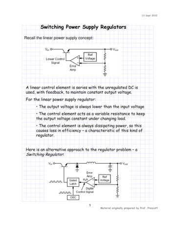
3Controls and Indicators3.1Front PanelFigure 1 - Front Panel(1)LED panel meter display with CV/CC indicator(2)Rear Control Indicator (lights up when using Preset/Remote Control/Set mode)(3)Output Voltage Control Knob (control main and auxiliary output voltage)(4)Output Current Control Knob (control main and auxiliary output current limit)(5)Power ON/OFF Switch(6)Auxiliary Output Terminal (max 5 A)Note:Please see Section 4.1.4 for more details on using both main andauxiliary output terminals together.7
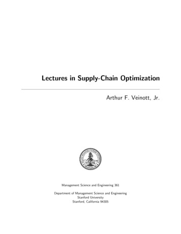
3.2Rear PanelFigure 2 - Rear Panel(7)Main Output Terminal (max 5 A for 1685B / 10 A for 1687B / 20 A for 1688B)Note:Please see Section 4.1.4 for more details on using both main andauxiliary output terminals together.(8)Mode Selection Switch (Normal, Preset, Remote Control, Set Modes)(9)Recall Preset Selection Switch(10)Analog Remote Control Terminal(11)Cooling Fan Air Intake Grille(12)AC Input Plug and Fuse Compartment(13)USB Port (for PC remote control)8
4Operating InstructionsSafety Precautions This power supply is for indoor use only. Do not expose the power supply to sun, high humidity, or dustyenvironments. Never remove the metal cover of the power supply while AC power isconnected. Never touch the unit when your hands are wet. Never block the ventilation slots and cooling fan air intake window. Never attempt to repair the power supply. Incorrect re-assembly mayresult in a risk of electric shock or fire. Never use the power supply for a load requiring higher current than thedesigned value. Otherwise it may damage the power supply. Place the power supply on a flat surface with sufficient clearance and dry,dust-free surroundings for ventilation.This series has three models with different output voltage and current ranges. Makesure you have purchased the correct one.Model NumberOutput Voltage RangeTotal Rated Current1685B1 – 60 V0–5A1687B1 – 36 V0 – 10 A1688B1 – 18 V0 – 20 ATable 1 - Model Table9
4.1Using the Power Supply4.1.1ConnectionTo connect the equipment to the power supply, follow the steps below.1. Check the rating label of the power supply and confirm that it complies withyour AC mains voltage.2. Connect the power supply to the AC mains using the provided power cordand make sure the Mode Selection Switch is in the Normal position.3. Hook up the red ( ) terminal to the positive polarity input of the equipmentand the black (-) terminal to the negative polarity input of the equipment.4. Switch on the power supply first. The panel meter and green CV indicatorshould light up again.5. Switch on the equipment. The panel meter and green CV indicator shouldstill remain green.6. When an operation is finished, switch off the equipment first and thenswitch off the power supply.4.1.2Self Test SequenceThe power supply will perform a series of self checks when it is switched on. Thetable below shows the self test sequence.Front Panel DisplayTestTo show software version10
Front Panel DisplayTestSegment checkC.V. indicator checkC.C. indicator checkRear control indicatorcheckReturn to C.V.Start power supply checksOvervoltage protectioncheckOverload protection check11
Front Panel DisplayTestOvertemperatureprotection checkFan checkOutput off (remotecontrol mode)Table 2 - Self Test SequenceThe LED and other indicators on the front panel will be turned on. When the coolingfan is being checked, a loud fan noise can be heard.After the self checks, the CV, V, and A LED indicators are lit up displaying voltage and0.0 current. To find out about the set CC current level, just turn the current controlknob one click in either direction. The current display returns to 0.0 after a fewseconds.4.1.3Control KnobsThe rotary encoder control knobs have fine and coarse tuning with clickingmovement.Push the knobs to toggle between coarse and fine tuning. You will notice the subtlechange in brightness of LED.Adjust the knobs to your desired values through coarse and fine tuning. The displaywill resume its normal brightness after a few seconds to confirm your adjustment.12
4.1.4Using Both Main and Auxiliary OutputsThe power supply has a main output in the rear and an auxiliary output in the frontthat can be used separately or together.The main and auxiliary output both share the same voltage and current control knobsand will output the same voltage and current up to the maximum output ratings ofthe power supply and terminals. When using both the main and auxiliary outputstogether, the power supply will automatically total the currents supplied to bothterminals up to the current limit of the power supply and show the total current onthe display.For example, setting the voltage and current outputs for model 1688B (1-18 V, 0-20A) to 18 V and 20 A would output 18 V at both main and auxiliary terminals and allowyou to draw up to a total of 20 A between the two terminals. If there is a 5 A load atthe auxiliary terminal, the most current you can draw from the main output is 15 A.If the power supply reaches its set current limit at any time, the power supply will gointo CC mode and the loads together will draw up to the total value of the currentlimit. Distribution of current between the main and auxiliary terminals will varydepending on the loads.Note:4.21685B: Total rated current (Aux. Main) is 5 A1687B: Total rated current (Aux. Main) is 10 A1688B: Total rated current (Aux. Main) is 20 AControl ModesThere are four different control modes for the power supply: NormalPresetSetRemote ControlTo select a mode, slide the Mode Selection Switch on the rear of the unit.13
Note:4.2.1The power supply is factory preset to Normal Mode with maximumcurrent level.Normal ModeThis is the factory preset mode and the power supply output voltage and current arecontrolled by the dual action dial knobs.Push the knobs to toggle the coarse and fine tuning. You will notice the subtlechange in brightness of LED.Adjust the knobs to your desired values through coarse and fine tuning. To check thepreset current level, turn the Current Knob lightly in any direction.The display will resume its normal brightness after a few seconds to confirm youradjustment.4.2.2Preset ModeIn this mode, the Rear Control light is ON to indicate panel voltage and currentcontrols are deactivated.There are three presets P1/P2/P3 on the Recall Selection Switch. The factory presetvalues are shown in Table 3.The user can also set custom output voltage and current using Set Mode. Please referto Section 4.2.3 for details.Recall No.Output VoltageOutput CurrentP15VMaximumP213.8 VMaximumP3Model 1685B: 55 VModel 1687B: 25 VModel 1688B: 15 VMaximumTable 3 - Default Presets14
4.2.3Set ModeFirst, enter Set Mode by pushing Mode Selection Switch to “Set” position.To define the preset output P1/P2/P31. Select the Recall Switch to the position you want to set: P1, P2, or P3.2. Adjust the front panel voltage control knob to set your desired voltagevalue.3. Adjust the front panel current control knob to set your desired current limitvalue.4. Repeat the procedure for remaining presets P1, P2, or P3 if desired.5. Move Mode Selection Switch from “Set” to “Preset” position to confirm yoursettings.To reset the unit back to factory settings1. Turn OFF the power supply.2. Push and hold both front panel voltage and current control knobs at thesame time.3. Turn ON the power supply.4. Release front panel voltage and current control knobs.Note: All the set values in the presets will be saved even after the power supplyhas been turned off.Always check output voltage of Presets before connecting to load.To check the preset values, move Mode Selection Switch to “Preset”position.Move the Recall Switch to P1, P2, or P3.The voltage and current settings of corresponding presets P1, P2, or P3 willbe shown on the panel meters.15
4.2.4Analog Remote Control ModeSelect this mode to control the output voltage and current via remote controlconnector. Please refer to Section 5.1 for more details.5Remote ControlThere are two methods to remotely control voltage and current.Note: Both methods require the remote control connector plug to be set up in orderfor analog remote control mode to be functional; otherwise the unit will be in CCmode all the time.5.1Analog Remote ControlSet up the provided remote connector plug.(a)Remove the black portion of the remote control connector plug by removingthe screw as shown in Figure 3.Figure 3 - Remote Control Connector(b)Solder 5 wires (22AWG) to pins 1, 2, 3, 4, and 5 of pin plug. Refer to Figure 4for pin numbers.16
Figure 4 - Pin Numbers(c)Make sure the load is disconnected and the power supply is OFF.(d)Plug the remote connector plug into the analog remote control terminal of thepower supply.(e)Secure the remote connector plug to the terminal socket by screwing in theconnector ring (Figure 5).Figure 5 - Connector RingThen, you can choose one of the following two methods to use the analog remotecontrol feature: (1) Using two external variable DC voltage sources or (2) using two 5kΩ variable resistors.17
5.1.1Using Two External Variable DC Voltage SourcesPINFUNCTIONSREMARKS1Internal DC 5 VLess than 50 mA2Voltage Adjust0–5V3Current Adjust0–5V4Ground5Output OFF6N/A7N/A8N/AShort to GroundTable 4 – Remote Connector Plug Pin Assignment for External Variable Voltage SourcesA variable external DC voltage source of 0 – 5 V is fed into the analog remote controlterminal to adjust the output voltage level of both Main and Auxiliary output.WARNING: Do not input higher than 5 V, otherwise the overvoltage protection(OVP) will be triggered.1. Make sure the load is disconnected and the power supply is OFF.2. Connect pin 2 to positive polarity of first external voltage source and pin 4 tonegative polarity of first external voltage source.3. Connect pin 3 to positive polarity of second external voltage source and pin4 to negative polarity of second external voltage source.4. Turn the remote control ON/OFF switch to ON position.18
5. Switch on the power supply.6. Check the output voltage range of the power supply by varying the externalvoltage source for voltage adjustment from 0 to 5 V.7. Short circuit the main output with an 8AWG gauge wire and check thedisplay for CC setting by varying the external voltage source for currentadjustment from 0 to 5 V.8. Switch off the power supply.5.1.2Using Two 5 kΩ Variable Resistors1. Make sure the load is disconnected and the power supply is OFF.2. Prepare two 5 kΩ variable resistors and connect wires from pins 1, 2, 3, and4 as shown in Figure 7.Figure 6 - Variable 5 kΩ Resistors Setup19
PINFUNCTIONSREMARKS1Internal DC 5 VResistor end2Voltage AdjustVariable part of resistor3Current AdjustVariable part of resistor4GroundResistor end5Output OFFShort to Ground6N/A7N/A8N/ATable 5 – Remote Connector Plug Pin Assignment for Variable Resistors3. Turn the remote control ON/OFF switch to ON position.4. Switch on the power supply.5. Check the output voltage range of the power supply by varying the 5 kΩvariable resistor for voltage adjustment.6. Short circuit the main output with 8AWG gauge wire and check the displayfor CC setting by varying the 5 kΩ variable resistor for current adjustment.7. Switch off the power supply.5.1.3Enable and Disable the OutputThis remote output on/off control can be activated in any of the modes.By default, Pin 5 is open and output is on.20
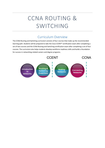
Shorting Pin 5 to Pin 4 (ground) will turn the output off.When output is off, the CV and CC LED will flash. The current output voltage andcurrent setting will show on the panel meter.You can also adjust the output by voltage and current control knob to your desiredvalue when output is off.5.2PC Interface ControlNote: The power supply must be in Normal Mode for PC interface control.5.2.1General Functions and DisplayThe remote control PC software will display all output voltage, current, and powerreadings. Power supply voltage and current values can be set in two different ways.Values can either be entered via keyboard or set by clicking on the displayed voltageand current setting (left click to increase value, right click to decrease value). Theoutput status is also shown and can also be clicked to set the power supply outputON or OFF.Figure 7 - PC Software General Functions and Display21
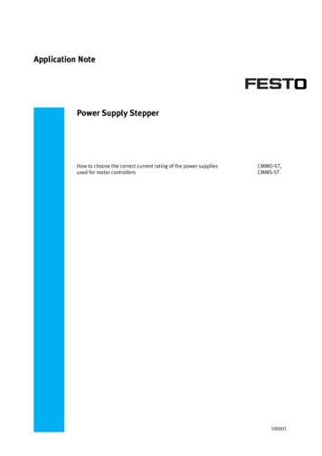
5.2.2External Timed ProgramExternal Timed Program is completely controlled by the PC. The PC counts the steptime and changes the specified voltage and current levels of the power supply.Figure 8 - External Timed ProgramExternal Timed Program Procedure1. Select External Timed Program tab to switch to the External Timed Programfunction.2. Enter voltage, current, and time parameters for number of steps needed intimed program. (Maximum of 20 steps can be entered)3. Specify desired number of running cycles. Up to 999 running cycles can beentered. Enter 0 for continuous cycle.4. To run the timed program, click the “Run” button.5. To save the table, enter Table Name in box and click the “Save Table” icon.The timed program table data can be classified, stored, exported to a csvfile, deleted, printed, or retrieved for use at any time.6. To delete all data in the table, click the “Clear Table” button.22
5.2.3Internal Preset MemoryThe Internal Preset Memory tab allows you to define the power supply’s presetsremotely.Figure 9 - Internal Preset MemoryInternal Preset Memory Procedure1. Select Internal Preset Memory tab to switch to the Internal Preset Memoryfunction.2.Enter in desired Voltage and Current values for Presets 1, 2, and 3.3.Click “Set” to select and save Presets.4.To get power supply’s currently stored presets, click the “Read from PS” button.5.Retrieved data will be shown in red if they exceed the present preset uppervoltage and current limit value.6.To save the table, enter Table Name in box and click “Save Table” icon. Data ofdifferent groups of presets can be classified, stored, exported to a csv file,printed, or retrieved for use at any time.7.To delete all data in the table, click the “Clear Table” button.23
5.2.4Data LogThe Data Log window can be used to view present or stored output data. Allparameters at the bottom of the window can be changed via direct entry from the PCand confirmed by pressing Enter or selecting the values from the drop down menu.Figure 10 - Data Log WindowParameters in Data LogV Min: Minimum voltage levelV Max: Maximum voltage levelC Min: Minimum current levelC Max: Maximum current levelW Min: Minimum power level in wattsW Max: Maximum power level in wattsT Min: Time minimumT Len: Time length24
To save a data log, enter Log Name in box and click the “Save Log” icon.After saving, the log can be retrieved by selecting it in the Log Name drop downmenu.Data logs can be classified, stored, exported to a csv file, printed, or retrieved for useat any time.THE TIME FRAME CONCEPT OF DATA LOGThe data logging function starts when the software begins to run.When T Min is set to 0 seconds, it means the data is in real-time and the length oftime lapsed is on the left hand side of the Time Minimum.T Len is the length of time lapsed starting from the Time Minimum.Both parameters are adjustable so that any time period of the log can be displayedfor analysis.In the figure below, T Min is set to 10 seconds and T length to 120 seconds. Thedisplay shows the output data starting at 0 seconds ago and ending at the 130second mark.Figure 11 - Time Minimum and Time Length25
5.2.5SettingsUse this tab to configure your settings.Figure 12 - Settings ConfigurationData Log Sampling Time: You can select your desired data log sampling time from 1second and up.Voltage Upper Limit (UVL) Setting: You can set your output voltage upper limit valueto safeguard your low voltage applications.Current Upper Limit (UCL) Setting: You can set your output current upper limit valueto safeguard your low current applications.5.2.6Command SetNote: In order to use remote commands, please make sure to use the followingcommunication settings - Baud rate: 9600, Data bits: 8, Parity: none, Stop bits: 1. Ifyou are using HyperTerminal, make sure to check your ASCII setup to not append linefeeds.26
Command line format: COMMAND parameter1 parameter2 [CR]Current value will have one decimal place for models 1687B and 1688B, and twodecimal places for Model 1685B.Command code &Return valueFunctionExampleInput command:VOLT{ voltage }[CR]Set voltage level voltage 000-XXXInput command:VOLT010[CR]Return value:OK[CR]Return value:OK[CR]Sets voltage level to 1.0 VInput command:CURR{ current }[CR]Set current level current 000-XXXReturn value:OK[CR]Input command:CURR025[CR]Return value:OK[CR]Sets current level to 2.5 AInput command:PROM{ preset 1voltage }{ preset 1current }{ preset 2voltage }{ preset 2current }{ preset 3voltage }{ preset 3current }[CR]Set power supplyInput command:preset memory values PROM011022033044055066 preset X voltage 000-XXX preset X current 000-XXXReturn value:OK[CR]Get voltage andcurrent setting valuesfrom power supplyInput command:GETS[CR]Return value:OK[CR]Input command:GETS[CR]Return value:[voltage][current][CR] [voltage] 000-XXXOK[CR][current] 000-XXXSets preset 1 voltage and currentto 1.1 V and 2.2 A, preset 2voltage and current to 3.3 V and4.4 A, and preset 3 voltage andcurrent to 5.5 V and 6.6 AReturn value:025051OKIndicates voltage setting is 2.5 Vand current setting is 5.1 A27
Command code &Return valueInput command:GETD[CR]FunctionExampleGet display voltage,current, and statusreading from powersupplyInput command:GETD[CR]Return value:[voltage][current][status][CR][voltage] 0000-XXXXOK[CR][current] 0000-XXXX[status] 0 1 (0 CV,1 CC)Return value:030201450OKInput command:GETM[CR]Get preset memoryvaluesInput command:GETM[CR]Return value:[preset 1 voltage][preset 1 current][CR][preset 2voltage][preset 2current][CR][preset 3voltage][preset 3current][CR]OK[CR] preset 1 2 3voltage 000-XXX preset 1 2 3current 000-XXXReturn value:015015025025035035OKIndicates voltage reading is 3.02V and current reading is 1.45 A.Power supply is in CV modeIndicates preset 1 voltage andcurrent is 1.5 V and 1.5 A, preset2 voltage and current is 2.5 Vand 2.5 A, preset 3 voltage andcurrent is 3.5 V and 3.5 AInput command:Set voltage andRUNM{ memory }[CR current using values]saved in presetmemory locationsReturn value:OK[CR] memory 0 1 20 preset 1 values1 preset 2 values2 preset 3 values28Input command:RUNM0[CR]Return value:OK[CR]Sets voltage and current usingvalues from memory location 1
Command code &Return valueInput command:SOUT{ output }[CR]Return value:OK[CR]FunctionExampleOutput On/Off control Input command:SOUT1[CR] output 0 10 ONReturn value:1 OFFOK[CR]Switches output OFFInput command:SOVP{ voltage }[CR]Set upper voltage limit Input command:of power supplySOVP151[CR]Return value:OK[CR] voltage 000-XXXReturn value:OK[CR]Sets upper voltage limit to 15.1 VInput command:SOCP{ current }[CR]Set upper current limit Input command:of power supplySOCP108[CR]Return value:OK[CR] current 000-XXXReturn value:OK[CR]Sets upper current limit to 10.8AInput command:GOVP[CR]Get upper voltagelimit of power supplyInput command:GOVP[CR]Return value:[voltage][CR]OK[CR][voltage] 000-XXXReturn value:152OKIndicates upper voltage limit isset to 15.2 V29
Command code &Return valueFunctionExampleInput command:GOCP[CR]Get upper currentlimit of power supplyInput command:GOCP[CR]Return value:[current][CR]OK[CR][current] 000-XXXReturn value:052OKIndicates maximum current limitis set to 5.2 AInput command:GMAX[CR]Get power supplyInput command:maximum voltage and GMAX[CR]current valuesReturn value:Return value:[voltage][current][CR] voltage 000-XXX180200[CR]OK[CR] current 000-XXX OK[CR]Indicates maximum voltage is18.0 V and maximum current is20.0 A30
6Faults and Troubleshooting6.1OVP: Overvoltage ProtectionThis unit has a built-in tracking overvoltage protection feature. In the event of theoutput voltage becoming greater than the set value (see specified range fromSpecifications section), protection will be triggered, and the output power will becut off. OVP warning will appear as shown below.Figure 13 - Overvoltage ProtectionTo reset the warning, switch off the unit and remove all connected devices. Switchthe unit back on again and it should resume normal operation. If the problempersists, please contact B&K Precision.6.2OTP: Overtemperature ProtectionThere is a thermo sensor inside the unit to monitor and prevent the unit from gettingtoo hot. When OTP is triggered, there is no output and the following warning willappear on the LED display.31
Figure 14 - Overtemperature ProtectionWhen you get this warning, sw
1. Check the rating label of the power supply and confirm that it complies with your AC mains voltage. 2. Connect the power supply to the AC mains using the provided power cord and make sure the Mode Selection Switch is in the Normal position. 3. Hook up the red ( )