Transcription
Switch ModeDC PowerSuppliesSEC-1235SEC-1235MOwner'sManualPlease read thismanual BEFOREinstalling yourPower Supply.
OWNER'S MANUAL IndexSECTION 1Important Safety Instructions. 3SECTION 2Layout & Dimensions . 5SECTION 3Description & Overview . 7SECTION 4Installation . 9SECTION 5Operation. 13SECTION 6Limiting Electro-Magnetic Interference (EMI) . 15SECTION 7Troubleshooting Guide . 18SECTION 8Specifications . 19SECTION 9Warranty. 21Disclaimer of LiabilityUNLESS SPECIFICALLY AGREED TO IN WRITING, SAMLEX AMERICA INC.:1. MAKES NO WARRANTY AS TO THE ACCURACY, SUFFICIENCY OR SUITABILITY OF ANY TECHNICAL OR OTHER INFORMATIONPROVIDED IN ITS MANUALS OR OTHER DOCUMENTATION.2. ASSUMES NO RESPONSIBILITY OR LIABILITY FOR LOSSES, DAMAGES, COSTS OR EXPENSES, WHETHER SPECIAL, DIRECT,INDIRECT, CONSEQUENTIAL OR INCIDENTAL, WHICH MIGHT ARISE OUT OF THE USE OF SUCH INFORMATION. THE USE OFANY SUCH INFORMATION WILL BE ENTIRELY AT THE USERS RISK.Samlex America reserves the right to revise this document and to periodically make changes to the contenthereof without obligation or organization of such revisions or changes.Copyright Notice/Notice of CopyrightCopyright 2018 by Samlex America Inc. All rights reserved. Permission to copy, distribute and/or modify thisdocument is prohibited without express written permission by Samlex America Inc.2 SAMLEX AMERICA INC.
SECTION 1 Important Safety Instructions1.1 CAUTION: RISK OF ELECTRIC SHOCK! DO NOT OPEN!WARNING—TO REDUCE THE RISK OF FIRE OR ELECTRIC SHOCK, DO NOT EXPOSE THISAPPLIANCE TO RAIN OR MOISTURE. THERE ARE NO USER SERVICEABLE PARTS INSIDE —REFER TO QUALIFIED SERVICE PERSONNEL.1.2 SYMBOLSThe following safety symbols will be used in this manual to highlight safetyand information:WARNING!Indicates possibility of physical harm to the user in case of non-compliance.MISE EN GARDE! L’utilisateur pourrait se blesser lorsque les consignes de sécurité ne sont passuivies.!CAUTION!Indicates possibility of damage to the equipment in case of non-compliance.!ATTENTION!Il y a un risque d’endommager l’équipement lorsque l’utilisateur ne suit pasles instructions.iINFOIndicates useful supplemental information.1.3 GENERALPlease read before using your power supply:1. It Is recommended that you return your power supply to a qualified Samlex dealerfor any service or repair. Incorrect assembly may result in electric shock or fire.2. To reduce the risk of electric shock, unplug the power supply from the outlet beforeattempting any maintenance or cleaning. Turning off controls will not reduce this risk.3. An extension cord should not be used unless absolutely necessary. If an extensioncord must be used make sure that the pins on the plug are the same number, sizeand shape as those of the original power supply plug.4. Place the unit in an area that will allow air to flow freely around the unit. DO NOTBLOCK OR OBSTRUCT vent openings on the side/bottom of the unit.5. Keep the unit away from moisture and water.6. NEVER operate the units in parallel.SAMLEX AMERICA INC. 3
SECTION 1 Important Safety Instructions1.4 GROUNDINGWARNING!Your power supply should be grounded to reduce the risk of electric shock. Thepower supply is equipped with grounding conductor and grounding plug.The cord must be plugged into an outlet that is properly installed and groundedin accordance with all local codes and ordinances. Never alter the AC cord ofplug provided. If the cord will not fit the outlet, have a proper outlet installed byqualified electrician. Improper connection can result in risk of electric shock.MISE EN GARDE! Votre alimentation doit être mis à la terre pour réduire le risque de chocélectrique. L’alimentation est équipé d’un conducteur de mise à la terre etde mise à la terre. Le cordon doit être branché dans une prise de courant correctement installéeet mise à la terre conformément à tous les codes et règlements locaux. Nemodifiez jamais le cordon secteur de la prise fournie. Si le cordon ne s’adaptepas la prise, faites installer une prise adéquate par un électricien qualifié.Une connexion incorrecte peut entraîner un risque de choc électrique.1.5 CONNECTION TO A BATTERYDO NOT USE THE POWER SUPPLY FOR DIRECT CHARGING OF BATTERY OR DIRECTCONNECTION TO A BATTERY FOR BATTERY BACK-UP. (Please read Section 3.5).4 SAMLEX AMERICA INC.
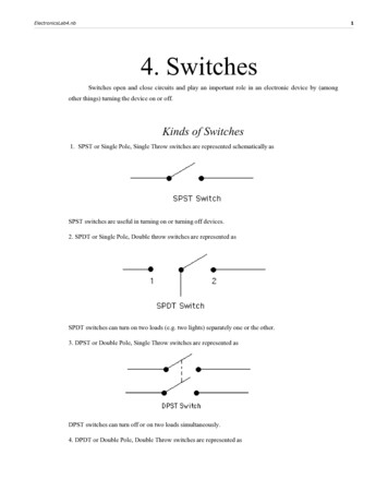
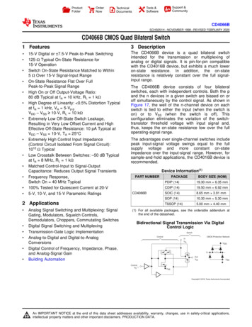
SECTION 2 Layout & Dimensions612.1 LAYOUT SEC-12351857.753.313.51902081904.52.52.5180Figure 2.1 Layout & Dimensions - SEC-12351. Lighted Power ON/OFF Rocker Switch (Lights Red when ON)2. AC Power Cord Inlet: Type “IEC 60320-C14” for detachable power cord with “IEC 60320-C13”connector on one end and NEMA5-15P plug on the other end.3. Black Negative (-) DC Load Terminal{Tubular hole Dia 5mm/0.2” and set screw(5/64” Hex Socket Head, #10, 24 TPI, 5/16” long)}*4. Red Positive ( ) DC Load Terminal5. Ventilation slots (Additional row of ventilation slots in the bottom - not shown)* NOTE: 5/64” Hex key and 2 spare set screws have been providedDimensions:W x D x H 185 x 208 x 61 mm7.28 x 8.19 x 2.40 inSAMLEX AMERICA INC. 5
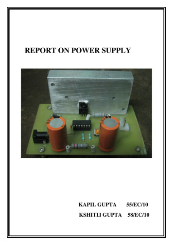
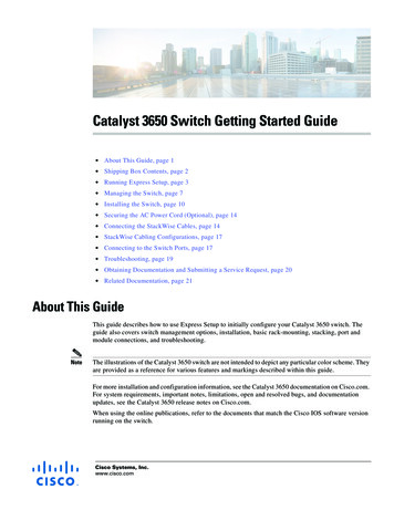
SECTION 2 Layout & Dimensions612.2 LAYOUT SEC-1235M7.753.318513.51902081908.52.51802.5Figure 2.2 Layout & Dimensions - SEC-1235M1. Lighted Power ON/OFF Rocker Switch (Lights Red when ON)2. AC Power Cord Inlet: Type “IEC 60320-C14” for detachable power cord with “IEC 60320-C13”connector on one end and NEMA5-15P plug on the other end.3. Black Negative (-) DC Load Terminal{Tubular hole Dia 5mm/0.2” and set screw(5/64” Hex Socket Head, #10, 24 TPI, 5/16” long)}*4. Red Positive ( ) DC Load Terminal5. Air inlet slots for cooling fan (cooling fan and air outlet slots at the bottom - not shown)* NOTE: 5/64” Hex key and 2 spare set screws have been providedDimensions:W x D x H 185 x 212 x 61 mm6 SAMLEX AMERICA INC.7.28 x 8.35 x 2.40 in
SECTION 3 Description & Overview3.1 DESCRIPTIONSEC-1235 / SEC-1235M are switched mode power supplies which convert 120 VAC, 50/60Hz (or 230 VAC, 50/60 Hz*) to regulated 13.8 VDC based on pulse width modulation(PWM) control.*NOTE: The units are factory preset to operate from input voltage of 120 VAC, 50/60 Hz.These may be set to operate from input voltage of 230 VAC, 50/60 Hz by changing internal setting described at Section 4.5.2.!CAUTION!UL listing is not valid for 230 VAC input option. !ATTENTION!Inscription UL n’est pas valide pour l’option d’entrée 230 VAC. 3.2 FEATURES-Based on switched mode technology and PWM control. Switching frequency: 30.5 KHz-SEC-1225M comes with Voltmeter and Ammeter-Compact and lightweight.-High efficiency and less heat dissipation.-Protected against short circuit, over current and over voltage(through PWM controller).-Forced air cooling and over temperature shut down.-UL listed and approved.-Complies with FCC part 15(B) for radiated & conducted noises for Class-Bdigital devices.3.3 COOLING AND OVER TEMPERATURE PROTECTIONThe units are cooled by convection and by forced air. A temperature controlled fan hasbeen provided to improve cooling at higher loads. The fan is controlled by a sensormounted on the power transformer. THE FAN WILL BE OFF AT LOWER LOADS. It willcome on only when the temperature of the power transformer is 60ºC 5ºC / 140ºF 9ºF due to higher loads or higher ambient temperature or poor cool air circulationaround the unit. The fan will switch off automatically at 40ºC 5ºC / 104ºF 9ºF. Incase the fan fails or the air flow is blocked, a second temperature sensor mounted onthe power transformer will activate over temperature shut down at 105ºC 5ºC /221ºF 9ºF. The output voltage will be automatically resumed once the unit cools downto 75ºC 5ºC / 167ºF 9ºF. PLACE THE UNITS IN A WELL VENTILATED OPEN AND COOLAREA. DO NOT BLOCK THE OPENINGS AT THE FAN DISCHARGE ON THE BOTTOM ANDTHE SUCTION OPENINGS ON THE SIDES.SAMLEX AMERICA INC. 7
SECTION 3 Description & Overview3.4 BATTERY CHARGING & BATTERY BACK-UPWARNING!These units are power supplies and not battery chargers. Do not connect theseunits directly to a battery.MISE EN GARDE! Ces unités sont des unités d’alimentation et non pas les chargeurs de batterie.Ne pas connecter ces appareils directement à une batterie.These units should NOT BE DIRECTLY CONNECTED TO A BATTERY for charging or forbattery back-up. Battery charging and battery back-up may be undertaken only when thebattery is connected through suitable external isolating diodes and charge limiting resistor.The isolating diode will ensure that the battery does not back power the power supply.When a battery is deeply discharged, it will initially draw a very large charging currentand thus, will force the power supply into current limit mode for prolonged periods.This is harmful for the power supply. The charge limiting resistor will limit the chargingcurrent, thereby, ensuring that the maximum charging current is well below the currentlimit value of the power supply.iINFOIt is recommended that optional battery back-up module BBM-12100 may beused to convert SEC-1235 / SEC-1235M for battery back-up application.8 SAMLEX AMERICA INC.
SECTION 4 Installation4.1WARNING!1. Before commencing installation, please read the safety instructionsexplained in Section 1 titled “Important Safety Instructions”.2. It is recommended that the installation should be undertaken by aqualified, licensed / certified electrician.3. Various recommendations made in this manual on installation will besuperseded by the National / Local Electrical Codes related to the location of the unit and the specific application.MISE EN GARDE!1. Avant de commencer l’installation, veuillez lire les instructions de sécuritéa expliqué à la section 1 intitulée “Instructions de sécurité importantes”.2. Il est recommandé que l’installation doit être effectuée par un technicien qualifié, autorisé / électricien certifié.3. Différentes recommandations faites dans ce manuel sur l’installationsera remplacée par la National / les codes électriques locaux liés àl’emplacement de l’unité et l’application spécifique.4.2 INSTALLATION DIMENSIONSRefer to Section 2, Figs 2.1 for installation dimensions for SEC-1235 and Section 2, Fig 2.2for installation dimensions for SEC-1235M.4.3 LOCATION OF INSTALLATIONPlease ensure that the following requirements are met:Working Environment: Indoor use.Cool: Heat is the worst enemy of electronic equipment. Hence, please ensure that theunits are installed in a cool area that is also protected against heating effects of directexposure to the sun or to the heat generated by other adjacent heat generating devices.Well ventilated: The units are cooled by convection and by forced air-cooling by temperature controlled fan on the bottom of the unit. The fan at the bottom draws coolair from air intake openings on the sides and discharges hot air through the exhaustopenings under the fan. To avoid shut down of the units due to over temperature, donot cover or block the ventilation / suction / exhaust openings or install the units in anarea with limited airflow. Keep a minimum clearance of 10” around the units to provideadequate ventilation. If installed in an enclosure, openings must be provided in theenclosure, directly opposite to the air-suction and air-exhaust openings of the unit.Dry: There should be no risk of condensation, water or any other liquid that can enteror fall on the units.SAMLEX AMERICA INC. 9
SECTION 4 InstallationClean: The area should be free of dust and fumes. Ensure that there are no insects orrodents. They may enter the units and block the ventilation openings or short circuitelectrical circuits inside the units.Protection against fire hazard: The units are not ignition protected and should not belocated under any circumstance in an area that contains highly flammable liquids likegasoline or propane as in an engine compartment with gasoline-fueled engines. Do notkeep any flammable / combustible material (i.e., paper, cloth, plastic, etc.) near the unitsthat may be ignited by heat, sparks or flames.Accessibility: Do not block access to the front panel. Also, allow enough room to accessthe AC inlet and the DC wiring terminals and connections at the back of the unit, asthey will need to be checked and tightened periodically.Preventing Radio Frequency Interference (RFI): The units use high power switching circuits that generate RFI. This RFI is limited to the required standard – FCC Part 15(B), ClassB. Locate any electronic equipment susceptible to radio frequency and electromagneticinterference as far away from the unit as possible. For additional information, pleaseread Section 6 titled “Limiting Electromagnetic Interference (EMI)”.4.4 MOUNTING ORIENTATIONThe units have air intake openings on the sides and exhaust openings at the bottom forthe cooling fan. The units should be mounted in such a manner so that small objectsshould not be able to fall easily into the units from these openings and cause electrical /mechanical damage. Also, the mounting orientation should be such that if the internalcomponents overheat and melt / dislodge due to a catastrophic failure, the melted /hot dislodged portions should not be able to fall out of the unit on to a combustiblematerial and cause a fire hazard. The size of openings has been limited as per thesafety requirements to prevent the above possibilities when the unit is mounted in therecommended orientations. In order to meet the regulatory safety requirements, themounting has to satisfy the following requirements:- Mount on a non-combustible material.- The mounting surface should be able to support the weight of the unit- Mount horizontally on a horizontal surface (e.g. table top or a shelf)- Mounting horizontally on a vertical surface – The unit can be mounted on a verticalsurface (like a wall) with the DC output terminals either facing up or downWARNING!Mounting the unit on a vertical surface with the ventilation slots on the sidesfacing up / down is NOT recommended. As explained above, this is to prevent(i) falling of objects into the unit through the slots causing short circuit or (ii)falling out of dislodged overheated / melted components on to a combustiblematerial in case of catastrophic internal failure.10 SAMLEX AMERICA INC.
SECTION 4 InstallationMISE EN GARDE! ontage de l’appareil sur une surface verticale avec les fentes de ventilation sur lesMcôtés vers le haut / vers le bas n’est pas recommandé. Comme expliqué ci-dessus, ils’agit d’éviter que (i) la chute d’objets dans l’unité à travers les fentes provoquantun court-circuit ou (ii) en tombant de délogé / composants surchauffés fondu sur unmatériau combustible en cas de défaillance interne catastrophique.4.5 AC SIDE CONNECTION4.5.1 Connection for nominal AC input voltage of 120VAC (range: 100-130VAC),50/60Hz (Factory preset condition)The unit has been factory preset for nominal AC input voltage of 120VAC (range:100130VC), 50/60Hz.120VAC power is fed to the unit through detachable, 120 VAC power cord supplied withthe unit. The power cord has the following specifications: Length of the cord: 6 ft Cable : 3 conductors (Line – black; Neutral – White; Grounding - Green), eachAWG #16 13A, 125V female connector “IEC 60320-C13” for power supply end.Insert this end into the AC Power Inlet on the unit (2, Figs 2.1 / 2.2) 13A, 125V “NEMA5-15” plug for connecting to 120 VAC outlet4.5.2 Connection for nominal AC input voltage of 230VAC (range: 200-260VAC),50/60Hz (will require internal jumper setting)The unit can also be operated from nominal AC input voltage of 230VAC (range: 200 to260VAC), 50/60Hz by internal jumper setting, changing internal fuse size and changingAC power cord as described below:4.5.2.1 Changing internal jumper settinga) Switch off the unit and unplug the AC power cord from the AC outlet supplyingAC power to the unit.b) Remove the top cover by unscrewing 4 screwsc) For 120VAC operation (factory preset condition), points marked “C” and “E” onthe Printed Circuit Board (PCB) have been connected (shorted) with a flexible,yellow colored jumper wire that has black colored Quick Disconnect Terminalat the 2 ends. To convert to 230VAC operation, disconnect the Quick ConnectTerminal of the jumper wire at point “C” by pulling it upwards. Insulate this endwith insulation tape and use a cable tie to tie it securely to the nearby wire bundle.4.5.2.2 Changing internal Fusea) For the factory preset 120 VAC operation, the internal AC input side Fuse israted at 250VAC, 8A. For 230VAC operation, remove this Fuse and replace with asimilar 250VAC, 4A Fuse (Littelfuse Part No. 0218004 or equivalent)SAMLEX AMERICA INC. 11
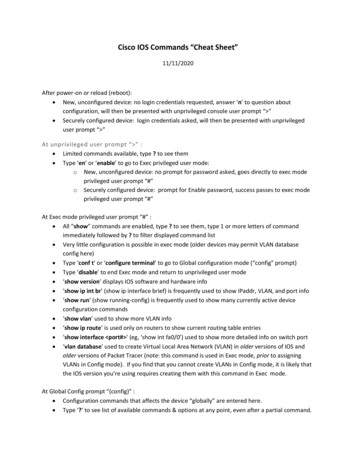
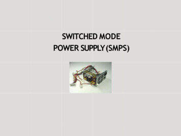
SECTION 4 Installation4.5.2.3 Changing detachable AC Power Corda) Change the supplied detachable AC power cord with detachable power cord thathas “IEC 60320 – C13” female connector for the power supply end and a plug onthe other end with 3 pin configuration to suit the 230V country specific outlet.4.6 DC OUTPUT CONNECTIONS4.6.1 DC Output TerminalsDC output is provided as follows: Red Positive Terminal (4, Figs 2.1 and 2.2):o Tubular Hole – Diameter 5 mm / 0.2”o *Set Screw: 5/64” Hex Socket Head Screw; #10, 24 TPI, 5/16” long Black Negative Terminal (3, Figs 2.1 and 2.2):o Tubular Hole – Diameter 5 mm / 0.2”o *Set Screw: 5/64” Hex Socket Head screw; #10, 24 TPI, 5/16” long**NOTE: The following have been provided for convenience:a) 5/64” Hex / Allen Key for the Hex Socket Head Screw.RETAIN THE HEX / ALLEN KEY FOR FUTURE USEb) 2 spare Hex socket head screws4.6.2 Pin Type of Terminal Lugs for Wiring to be Connected to DC Output TerminalsThe DC output terminals have a tubular hole with a set screw (See Section 4.6.1 abovefor specifications). As the DC terminals have been provided with a set screw, do notconnect bare stranded wire end directly to the DC output terminal as the strands willspread out when the set screw is tightened and all the strands may not be pinchedfirmly under the set screw. This will result in (i) reduction in effective area of crosssection for current conduction leading to increased voltage drop and overheatingalong output wiring and (ii) Sparking / loose connection under the set screw leadingto overheating / melting of the plastic material of the terminals. The ends of strandedwiring to be connected to the DC output terminals should be crimped to Pin Type ofTerminal Lugs that have been provided with the unit (see Fig 4.1). After crimping theTerminal Lugs, use insulating heat shrink tubing or tape to insulate the bare cylindricalportion of the lugs.Fig 4.1 Pin type of terminal lugs provided for termination ofstranded wiring to be connected to the DC input terminals.12 SAMLEX AMERICA INC.
SECTION 5 Operation5.1WARNING!1. Before commencing operation, please read the safety instructionsexplained in Section 1 titled “Important Safety Instructions”.2. Ensure that the unit has been installed as per guidelines given in Section 4titled “Installation”.3. The unit has been factory preset for operation from nominal AC inputvoltage of 120VAC, 50/60Hz. It the unit is to be operated from nominal ACvoltage of 230 VAC, 50/60 Hz, please change internal input jumper setting,internal fuse and AC power cord as per instruction given at Section 4 titled“Installation”.NOTE: If the unit is operated from 230VAC without making the abovechanges, the input section of the unit will be damaged andwarranty will be voided.MISE EN GARDE!1. Avant de commencer, veuillez lire les instructions de sécurité a expliqué à lasection 1 intitulée “Instructions de sécurité importantes”.2. S ’assurer que l’unité a été installée selon les directives données dans la section 4 intitulée “Installation”3. The unit has been factory preset for operation from nominal AC input voltageof 120VAC, 50/60Hz. It the unit is to be operated from nominal AC voltage of230 VAC, 50/60 Hz, please change internal input jumper setting, internal fuseand AC power cord as per instruction given at Section 4 titled “Installation”.NOTE: Si l’appareil est utilisé à partir de 230 VCA sans faire leschangements ci-dessus, la section d’entrée de l’appareil seraendommagé et et la garantie sera annulée.5.2 SWITCHING ON PROCEDUREa) Plug the supplied AC Power Cord to the AC Power Cord Inlet on the unit(2, Fig 2.1 / 2.2)b) Ensure that the power supply’s On/Off Switch (1, Fig 2.1 / 2.2) is in offposition (edge of the switch with marking “o” will be in pressed downcondition).c) Switch off the 12V DC load that is required to be powered from the power supply.d) Ensure that the ends of the Positive and Negative wires of the DC load tobe connected to the power supply have been properly terminated with PinType Terminal Lugs as explained at Section 4.6.2.e) Connect the Positive wire from the DC load to the Red Positive DC InputTerminal (4, Fig 2.1 / 2.2) of the power supply and the Negative wire fromthe DC load to the Black Negative DC Input Terminal (3, Fig 2.1 / 2.2) of thepower supply. Use 5/64” Hex Key provided with the unit to tighten the HexSocket Head set screws to ensure that the connections are secure and tightf) Plug the AC Power Cord to the AC outlet. Ensure that AC power is availablein the outlet.SAMLEX AMERICA INC. 13
SECTION 5 Operationg) Switch on the unit by pressing down on the edge of the switch marked“ – ”. Neon light inside the switch will be lightedh) 13.8 VDC will now be available at the DC output terminals (4, 3 in Fig 2.1 / 2.2)i) Now switch on the DC load5.3 SWITCHING OFF PROCEDUREa) Switch off the DC load firstb) Switch off the power supply by pressing down on the edge of the switchmarked “o”c) Unplug the AC power cord from the AC outlet5.4 TROUBLESHOOTINGRefer to the Troubleshooting Guide at Section 7 in case of any abnormal operation.SECTION 6 Limiting Electro-MagneticInterference (EMI)6.1!CAUTION! Conducted and radiated noises in this unit are limited as per the applicableNational / International Standards as detailed under Compliance: EMI inSection 8. This unit generates, uses and can radiate radio frequency energy and, if notinstalled and used in accordance with the instructions, may cause harmfulinterference to radio communications. However, this does not guarantee thatinterference will not occur in a particular installation. If this equipment doescause harmful interference to radio or television reception, which can bedetermined by turning the equipment off and on, the user is encouraged totry to correct the interference by one or more of the measures recommendedin the following paragraphs.!ATTENTION! Bruits et rayonnement dans cette unité sont limitées que par la législationnationale / normes internationales comme détaillé dans le cadre deconformité : EMI dans la section 8. Cet appareil génère, utilise et peut émettre une énergie de fréquenceradio et, s’il n’est pas installé et utilisé conformément aux instructions, peutcauser des interférences nuisibles aux communications radio. Cependant,14 SAMLEX AMERICA INC.
SECTION 6 Limiting Electro-MagneticInterference (EMI)cela ne garantit pas qu’aucune interférence ne se produira dans uneinstallation particulière. Si cet équipement provoque des interférencesnuisibles à la réception radio ou télévision, ce qui peut être déterminé enéteignant l’équipement, l’utilisateur est encouragé à essayer de corriger lesinterférences en prenant une ou plusieurs des mesures recommandées dansles paragraphes suivants.6.2 UN-INTENTIONAL RF NOISE GENERATED BY SWITCHED MODEPOWER SUPPLIES (SMPS)Switched Mode Power Supplies (SMPS) employ high frequency switching (30.5 KHz inthese units) and thus, are a source of radio interference, a recipient of radio interferenceand a conduit of radio interference. (Older Linear Type, low frequency 50 / 60 Hztransformer based power supplies do not employ high frequency switching voltages andwill be quieter as compared to SMPS).The emission sources originate in the switching devices due to their fast switchingcurrent transitions: harmonics of the switching frequency and broadband noise createdby under-damped oscillations in the switching circuit. The noise is both conducted andradiated through the input power cord and the DC output wiring to the radio.6.3 FILTRATION OF CONDUCTED NOISEThe conducted RF noise from this SMPS unit is limited to the maximum allowable levels byinternal filtration. The filtered RF noise currents ( few hundred micro Amps) are bypassedto the chassis of the power supply. The chassis is, in turn, connected to the Earth Groundpin of the AC input power cord (for Class 1 units). Thus, the filtered noise currents areintentionally leaked to the Earth Ground. This is termed as the “Earth Leakage Current”.6.4 EXCESSIVE RF OUTPUT INTERFERENCE BY SMPS DUE TOINCOMING RF INTERFERENCE WHEN POWERING RADIO TX / RXSMPS are also recipients of radio interference. The normal operation of the powersupply can be disturbed due to RF noise getting coupled into the power supply. Thus,the power supply may generate excessive RF noise and lose output voltage regulationdue to excessive transmitter energy being coupled through the AC / DC lines to thepower supply’s regulator feedback path. This may be due to antenna being too closeor due to the antenna or feed system not radiating properly. First, check the antennasystem SWR. Then, if necessary, relocate either the antenna or the power supply fartherapart. The receiver may “hear” the power supply. A slowly moving, slightly buzzingcarrier heard in the receiver may be caused by the antenna being too close. As with thetransmitter related noise pick up, a loose coaxial connector or a broken or a missingground may aggravate this problem. Normally, this noise will be below the backgroundSAMLEX AMERICA INC. 15
SECTION 6 Limiting Electro-MagneticInterference (EMI)or “band” noise. Increase the separation between the power supply and the receivingantenna. Use an outdoor antenna. This will reduce the amount of signal picked up fromthe power supply and also increase the amount of the desired signal.6.5 ADDITIONAL GUIDELINES FOR REDUCING RF NOISE Use additional appropriate AC Radio Frequency Interference (RFI) Power Line Filterrated for minimum 10A immediately before the AC input of the power supply.Filtered, Ferrite Coated Cord Set is another choice. These cord sets, with integralline interference filters, reduce Common and Differential Mode Interferencesover a wide frequency range. Because they are shielded, they are also effectiveagainst radiated interferences. In addition to the built-in filter networks, thecable conductors are coated with an RF absorbing ferrite compound. This providesadditional attenuation at high frequencies that is lacking in most regular LC filters.The RF absorption of the ferrite-coated cable avoids resonances at high frequencies,reducing the conducted and radiated RF noises even further. Use additional appropriate DC radio frequency interference (RFI) power line filterrated for minimum 35A immediately after the DC output of the power supply. Twist the Positive and Negative wires from the output of the power supply to the radio. The DC side Positive and Negative outputs of these power supplies are isolated fromthe chassis. As explained earlier, the noise currents are filtered to the chassis of theunit and the chassis is connected to the Earth Ground through the Earth Ground Pinof the AC power outlet receptacle. Avoid connecting (referencing) the DC Negativeoutput terminal of the power supply to the Earth Ground. Connect a ¼” wavelength of wire on the Negative terminal of the power supply.Connect one end of the wire to the Negative terminal and leave the other end free.The wavelength corresponds to the wavelength of the interfering frequency. (Maynot be practical for long wave lengths).[Formula: Wave length (Meters) 300 / frequency in MHz]6.6 COMBINED FILTERED NOISE CURRENTS FROM MULTIPLESMPS ON A BRANCH CIRCUIT MAY TRIP GROUND FAULT CIRUITINTERRUPTER (GFCI)During malfunction or an accident, the metal chassis of a device may get energized tounsafe voltage due to internal high voltage section coming in contact with the chassis.If a person standing on Earth touches this energized chassis, a leakage currentproportional to the person’s skin resistance will flow through the person’s body toEarth Ground. The leakage current through the body is higher when the skin contactresistance is lower i.e. if the skin is wet or wounded. This leakage current does notreturn to the power source but is dissipated in Earth Ground. A leakage current of16 SAMLEX AMERICA INC.
SECTION 6 Limiting Electro-MagneticInterference (EMI) 4 to 6mA could produce lethal electrical shock. Ground Fault Circuit Interrupter (GFCI)is used for safety against electrical shock due to leakage. GFCI measures the differencebetween the current sent to the load and returned from the load and will trip anddisconnect the power circuit if the difference is 4 to 6mA. GFCIs are normally installedin AC Branch Circuits feeding power outlets in wet areas like marine craft, RVs, spas,hot-tubs, kitchens, washrooms, etc.As explained earlier, RF noise filtration circuits in SMPS generate intentional EarthLeakage Current. SMPS are used extensively as DC power sources in modern dayelectrical / electronic devices e.g. Audio / Video / Computing devices, power supplies,battery chargers etc. A single GFCI outlet / GFCI breaker may be serving multiple SMPSloads and therefore, will be sensing the sum of all the Earth Leak
The isolating diode will ensure that the battery does not back power the power supply. When a battery is deeply discharged, it will initially draw a very large charging current and thus, will force the power supply into current limit mode for prolonged periods. This is harmful for the power supply