Transcription
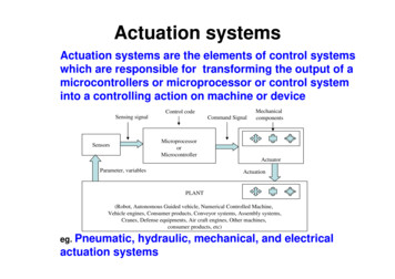
Actuation systemsActuation systems are the elements of control systemswhich are responsible for transforming the output of amicrocontrollers or microprocessor or control systeminto a controlling action on machine or deviceControl codeSensing signalSensorsCommand SignalMicroprocessororMicrocontrollerParameter, T(Robot, Autonomous Guided vehicle, Numerical Controlled Machine,Vehicle engines, Consumer products, Conveyor systems, Assembly systems,Cranes, Defense equipments, Air craft engines, Other machines,consumer products, etc)eg. Pneumatic,hydraulic, mechanical, and electricalactuation systems
Pneumatic & hydraulic actuationsystems Pneumatic deals with air pressure Hydraulic deals with fluid motion andpressure
Typical Hydraulic Power SystemWith a hydraulic system, pressurized oil (fluid) isprovided by a pump driven by an electrical motor. The pump pumps oilfrom a sump through anon return valve and anaccumulator to thesystem, from which itreturn to the sump. The pressure reliefvalve is to releasethe pressure if itrises above a safelevel, The accumulator isto smooth out anyshort termfluctuations in theoutput oil pressure
Typical Hydraulic Power System The Accumulator Work Accumulator is a container inwhich the oil is held underpressure against an externalforce, which involves gas within abladder in the chambercontaining the hydraulic fluid If the oil pressure rises then thebladder contracts increase thevolume the oil can occupy and soreduces the pressure. If the oil pressure falls the bladderexpands to reduce the volumeoccupied by the oil and soincreases its pressure.
Typical Pneumatic Power System A pressure reliefvalve providesprotection againstthe pressure in thesystem rising abovea safe level.An air receiver increases thevolume of air in the system andsmoothes out any short-termpressure fluctuations.In pneumaticpowersysteman electricmotordrives an aircompressor. The air inlet to thecompressor is likely tobe filtered and via asilencer to reduce thenoise level.Since the compressor increase thetemperature of the air, there likelyto be a cooling system and toremove contamination and waterfrom the air, a filter with water trapis used.
Directional Control Valves-1 Pneumatic and hydraulic systems usedirectional control valves to direct theflow of fluid through a system; itsON/OFF devices either completely openor closed They might be activated to switch thefluid flow direction by means ofmechanical, electrical or fluid pressuresignal
Directional Control Valves-2Common Types:1-Spool valve:Move horizontally within the valvebody to control flow 2-Rotary spool valve: have thesame idea, when rotates opensand closes ports
Directional Control Valves-3 3-Poppet valve: This valve is normally in closed condition. In this valve,balls, discs or cones are used in conjunction with valveseats to control the flow. When the pushbutton is depressed,the ball is pushed outof its seat and flowoccurs as a result ofport 1 beingconnected to port 2.When the button isreleased, the springforces the ball backup against its seatand so closes off theflow.
Directional Control Valves-4 Directional valvesFree flow can only occur in onedirection through the valve, flow in theother direction is blocked by spring.
Valve Symbols-1 The valve symbol consists of square for eachof its switching positions. Thus for theshown poppet valve there are two positions,one with the button not pressed and one withit pressed. Thus two positions valve will havetwo squares, a three positions valve havethree squares.Figure 7.7arrow headed lines areused to indicate thedirections of flow in eachpositionclosed flow lines; blockedoff(a) Flow path, (b) flow shut-off, (c) initial connections
Valve Symbols-2Symbols of Valve actuationIt indicates the various waysthe valves can be actuated(see Fig)Ports are labeled1 (or P) for pressure supply3 (or T) for hydraulic return port3 or 5 (or R or S) for pneumaticexhaust ports2 or 5 (B or A) for output portsValve actuation symbolsBolton, Mechatronics, 4th edition Pearson limited 2008
Valve Symbols-3Solenoid operated spool valveThe valve is actuated by a current passingthrough the solenoidand return to its original position by spring
Valve Symbols-4 Fig. shows the symbol for a 3/2 valve, the connectionis shown for initial state i.e. 1(P) is connected to 2(A); 3(R) is closed. When the solenoid is activated, it gives the stateindicated by the symbols used in the square towhich it is attached, i.e we now have 1(P) closed and2(A) connected to 3(R). When current through thesolenoid ceases the spring pushes the valve back toits initial position. The spring movementgives the state indicated bythe symbols used in thesquare to which it isattached.A 3/2 valveBolton, Mechatronics, 4th edition Pearson limited 2008
Valve Symbols-5 a simple exampleof an applicationof valves in aPneumatic liftsystemBolton, Mechatronics, 4th edition Pearson limited 2008
Pilot-operated valvesIn pilot operated system one valve is used to control asecond valve. In the Fig the pilot valve is small sizeand can be operated manually or by a solenoid.It is used to overcomewhen the force required tomove the ball shuttle in avalve can often be toolarge for manual orsolenoid operationBolton, Mechatronics, 4th edition Pearson limited 2008
Pressure control valve-1Three main types1- Pressure limiting valve: used to limit thepressure in a circuit to below some value2- Pressureregulationvalve: usedto controltheoperatingpressure in acircuit andmaintain it atconstantvalue.
Pressure control valve-23-Pressure sequence valve: are used tosense the pressure of an external lineand give a signal when it reaches somepreset value.(a) Pressure sequence valve symbol,(b) a sequential system
Hydraulic/Pneumatic linearactuators, Cylinders Both hydraulic and pneumaticactuators have the same principles,differences being in size The cylinder consists of a cylindricaltube along which a piston/ram can slide They are of two types: Single acting and double acting
Cylinders: Single acting Single acting: the control pressure isapplied to one side of the piston
Cylinders: Single actingWhen a current passes through the solenoid, the valve switchesposition and pressure is applied to move the piston along the cylinder.When current ceases, the valve reverts to it is initial position and the airis vent from the cylinder.Control of a single-acting cylinder with(a) no current through solenoid, (b) a current through the solenoid
Cylinders: Double acting Are used when control pressure areapplied to both side of the piston. Adifferent in pressure between the twosides results in motion of the piston(No spring).
Cylinders: Double actingCurrent through one solenoid causes the piston to movein one direction.Control of a double-acting cylinder withsolenoid, (a) not activated, b) activated
Cylinder: Example A hydraulic cylinder to be used to move a work piecein a manufacturing operation through a distance of250 mm in 15 s. if a force of 50 KN is required tomove the work piece, what is the required workingpressure and hydraulic liquid flow rate if a cylinderwith a piston diameter of 150 mm is available. Solution:πr2 ππ(0.15/2)2 0.0117 m2 A π The working pressure F/A 50x103/0.017 2.8 MPa The speed of a hydraulic cylinder flow rate of theliquid through the cylinder v Q/A Flow rate A.v 0.0117(0.250/15) 29.5x10⁻⁴ m3/s
Cylinder sequencingMany pneumatic or hydraulic control systemsmay require a sequence of extension andretraction of cylinders to occur. e.gSuppose we have two cylinders: A and BIf the start button pressed;{ piston A extends;If fully extended then piston B extends;If both A and B fully extended thenPiston A retracts;If A is fully retracted have piston Bretract}
4- If both A andB fully extendedthen Piston Aretracts2-piston Aextends;Cylinder sequencing3-If A fullyextendedthen pistonB extends;1- If the start button pressed;5-If A isfullyretractedhavepiston Bretract
Process Control Valve used to control the fluid flow rate A common form of pneumaticactuator used with process controlvalve is the diaphragm actuator. The diaphragm is made of rubberwhich sandwiched in it is centrebetween two circular steel discs. The effect of changes in the inputpressure is to move the central partof the diaphragm. The force F onthe shaft is the force that acting onthe diaphragm P x AWhere P: gauge pressure Controlpressure-atmospheric pressureA: diaphragm areaThe restoring force is provided byspring, so kx PA
Process ControlValve Valve bodies & Plugs Fig shows a crosssection of valve forthe control of rate offlow of a fluid. The plug restricts thefluid flow and so itsposition determinesthe flow rate
Process Control Valve Forms of Valve Body & Plug Single seated: closed more tightly but requiredmore force Double seated: less force is required, less tightly
Process Control Valve Shape of the Plug: determines the relationbetween the stem movement and the effect onthe flow rate 3 types are commonly used Fig shows the relation between the stemdisplacement & flow rate as % of maximum
Rotary actuators A linear cylinder can, withsuitable mechanical linkagebe used to produce rotarymovement through anglesless than 3600 Another alternative isshown in Fig. is called:vane type semi rotary.A pressure differencebetween the two partscauses the vane to rotate.
Actuation systems Actuation systems are the elements of control systems which are responsible for transforming the output of a microcontrollers or microprocessor or control system into a controlling action on machine or device eg. Pneumatic, hydraulic, mechanical, and electrical actuation system