Transcription
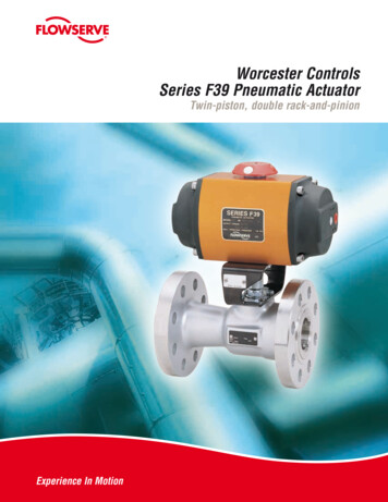
flowserve.comWorcester ControlsSeries F39 Pneumatic ActuatorTwin-piston, double rack-and-pinionExperience In Motion1
Series F39 Pneumatic ActuatorsHigh cycle pneumatic power for on/off or throttlingcontrol of rotary valves and dampersOne-piece steel piniondrive with full-length, blacknitrided rack-and-piniontooth engagement for greateroperational lifeNAMUR (VDI/VDE) topmounting for easy fitting andinterchangeability of switches,positioners, etc.Position indicatorprovides external indicationof valve positionCoro-lube coated aluminumconstruction for corrosionresistance and superior wearperformance on internal andexternal surfacesStainless steel fastenersimprove aesthetics and easeof maintenanceCorrosionprotected springsfor long servicelifeUnique unrestricted airflow through guide rodsgives fast operationspeeds as standard*Polishedstainless steelpiston guide rodsminimize internalwear and maximizeperformance lifeBalanced doublerack-and-pinioneliminates side loadsLong screwsto allow complete releaseof spring energy for safedisassembly when requiredISO 5211 mounting patternfor interchangeability of mountingkits and greater mechanical strengthMulti-spring conceptprovides variable torque/airpressure performance fromthe same actuator* Size 05F39 does not utilize piston guide rods.Features and Benefits Available as spring-return Safe disassembly, no Large range of sizes for Can be mounted for fail-openor fail-closed operationefficient torque matching 2I nternal parts are factory lubricated formaximum service life Standard NAMUR ancillaryattachmentspecial tools requiredor double-acting Limit stop for accuraterotational positioning International ISO5211 actuatormounting pattern
flowserve.comOperating PrincipleThe Series F39 Pneumatic Actuator design is based on the opposed rackand-pinion principle utilizing piston guide rods to guarantee part alignment.The fully supported guide rods minimize friction and wear between thepistons and the body bore.In the double-acting actuator, compressed air is applied to Port 1. The airflows through the rear guide rod and enters the center chamber to pushthe pistons apart, turning the shaft counterclockwise (as seen from above)to open the valve. During this action, air in the end caps is vented throughPort 2 via the front guide rod. Action is reversed, i.e., the valve is closed byapplying air to Port 2 and venting air through Port 1.In a fail-safe spring-return actuator, springs are located in the end caps.The number of springs in each cap depends on the available supply airpressure and required torque output. Air is supplied through Port 1 to thecenter chamber to push the pistons apart, which compresses the springs.During this action, air in the end caps is vented through Port 2 via the frontguide rod. When air is vented out through Port 1 (via a three-way solenoidvalve) the springs push the pistons back together thus closing the valve.Port 2 is continuously vented. The springs provide a dependable, safeclosure in the event of electrical or air supply failure.DOUBLE-ACTING ACTUATOR F39SPRING-RETURN ACTUATOR F39STOP VIEWTOP VIEWPORT 1AIR SUPPLYPORT 1AIR SUPPLYPORT 2VENT OUTPORT 2VENT OUTSTROKE OPENINGSTROKE OPENINGTOP VIEWSTROKE CLOSINGTOP VIEWPORT 1AIR EXHAUSTPORT 1AIR EXHAUSTPORT 2VENT INPORT 2VENT INSTROKE CLOSING3
Product Specifications Pneumatic Actuators are of a dual-pistondesign for compactness, highest torqueoutput, minimal air consumption andeven weight distribution (balanced) onthe valve stem. Actuators are equipped with two pistonguide rods to bear the lateral rack-andpinion thrust forces, increasing pistonseal life and eliminating the possibilityof cylinder scratching by the pistons.Elastomeric seals are not loaded asbearings. The rack is machined as part of thepiston in order to extend the actuator lifeand eliminate hysteresis. Actuators can have optional integralend-mounted limit switches, reducingoverall height and allowing the use ofthe actuator pinion for manual override(cannot be combined with limit stops). A ctuator housings are protected bothinternally and externally from corrosionusing an anodizing process. Single-acting actuators use multi-springsat each end to eliminate uneven forceson the pistons and are field adaptable tobalance reduced pressure air supplies. The torque is generated through a doublerack-and-pinion gearing mechanism withfull-length, uninterrupted engagement ofthe rack-and-pinion teeth. A ctuators can be supplied with integralsolenoid valving without the use oftransfer tubes. Valving incorporates failsafe action upon interruption of electricalsignal. Actuators are supplied with end mountedlimit stops for accurate position controlParts List/Material Specifications1210346117598Item No.12345678910114DescriptionBodyPinionPistonsEnd CapsGuide RodsBearings“O” RingsEnd Cap ScrewsSpringsPosition IndicatorLimit StopsMaterial/FinishAluminum (Extrusion) AnodizedCarbon Steel (Corrosion-Resistant Nitride Treatment)AluminumAluminum AnodizedStainless SteelAcetalNitrile RubberStainless SteelChrome Silicon (Corrosion-Resistant Coated)PolyethyleneStainless Steel
flowserve.comEnd Mounted Limit Stops3 10 96 10 3 Recognizing the increasing need for accurate rotationadjustment on many applications within the process industry,Worcester Controls has developed a unique method ofproviding this feature which is now standard on the actuator.The design takes advantage of the moving guide rods withinthe actuator and uses two stops in the end cap to limit theirtravel and therefore adjust the rotation of the actuator in bothdirections.The design allows for a nominal rotation of 90 providing 3 ofadjustable over travel at each end of the actuator stroke. The limitstop screws can also be used to adjust the under travel of theactuator by 10 at each end of the actuator stroke.End Mounted Solenoid BlockWatertight Class F Coil (Type 4, 4x)Inrush HoldingVoltageampsAmps24/60. 22/50 VAC0.360.24120/60. 110/50 VAC 0.080.05240/60. 220/50 VAC 0.040.0312 VDC0.380.3824 VDC0.200.20120 VDC0.040.04The solenoid end cap of each actuator is pre-drilled to VDE/VDI NAMUR 3845 to allow rapid attachment of either a doubleacting or spring-return solenoid control block.The double-acting solenoid control block provides extremely fineand independent adjustments for speed control on the openingand closing strokes of a double-acting actuator (20:1 ratio).The double-acting solenoid control block can be overridden bymanual operation of the control block spool.The spring-return solenoid control block provides an optionaladjustment for speed control on the spring stroke of a springreturn actuator. The advanced design prohibits environmentalingress to spring chamber during piston stroke extending actuatorlife.Both double-acting and spring-return styles return to theactuator “closed” position (pistons together) upon electrical failure.Hazardous Class H Coil (Type 4, 4x, 7, 9)InrushHoldingVoltageampsAmps24/60. 22/50 VACConsult Factory120/60. 110/50 VAC 0.100.05240/60. 220/50 VAC 0.050.0312 VDC0.380.3824 VDC0.190.19120 VDCConsult FactoryType 7 (UL & CSA listedfor Class I, Division I,groups A, B, C & D) andType 9 (UL & CSA listedfor class II E, F & G)The type 7 solenoid isalso rated 4, 4xAn extensive range of Weatherproof and Explosionproof coil optionsis available, along with a wide voltage selection including low-powerand intrinsically safe.W25NFA 2-position, 3-Way, Single Operator andW25NAA 2-position, 4-way, Single Operator NAMUR mounting Weatherproof and Hazardous Area Speed control – Standard Momentary override – Standard Interchangeable coils – Standard -40F to 180F - Standard Rebreather design - StandardW25NFA Three-WaySpring-Return SolenoidW25NAA Four-WayDouble-Acting Solenoid5
Torque OutputSizingDetermine appropriate valve torque requirements from valve literature. For double-acting actuators, select the actuator whose torque output atavailable air supply exceeds breakaway torque requirements of the valve. For detailed instructions, consult Worcester Controls Ball Valve ActuatorSelection Manual.For fail-closed, spring-return actuators, select the appropriate size actuator whose torque output at the end of the spring stroke (at available airsupply) is sufficient to close the valve.For fail-open spring-return actuators, select appropriate actuator whosetorque output at the end of the air stroke is sufficient to close the valveFor fail-open actuators, it is also necessary to determine that the torqueoutput at the start of the spring stroke exceeds breakaway requirementsof the valve.Spring-Return Actuator Torque Output Series 05F39 (in-lb/Nm)ModelNo.StrokeAir05F39Spring50 (3.4)2 SpringsStartEnd27163.11.842324.73.6Operating Pressure psi (Bar)60 (4.1)70 (4.8)2 Springs2 24.73.64.73.680 (5.5)4 SpringsStartEnd53376.04.253416.04.6Spring-Return Actuator Torque Output Air45F39SpringAir50F39Spring630 (2.0)4 2421222487149628116937171797420203439025934962938 96474885109055240 (2.7)4 49629312 00144707319163582750 (3.4)6 456584388574443916 064019293976221801103Operating Pressure psi (Bar)60 (4.1)8 4408779517799258520 0065024116122042725137970 (4.8)8 811206808779517799258520 300117524116122042725137980 (5.5)10 85960001227678109746469124073124 2811119628940146383270165490 (6.2)10 305481421475920109746469124073124 8834501750289401463832701654
flowserve.comDouble-Acting Actuator Torque Output (in-lb/Nm)ModelNo.Operating Pressure psi (Bar)70 (4.8)80 (5.5)30 (2.0)40 (2.7)50 (3.4)60 (4.1)90 (6.2)100 (6.9)110 5F3940F3942F3945F3950F39120 9215027503380400046175240586064807100Engineering DataStroke Time (seconds)*ModelNo.DoubleActingSpringReturnActuator Free Internal VolumeWith Max.*SpeedControlOpenCubic Inches3(in )LitresTubing RequirementsClose DA OnlyCubic InchesLitres3(in )Under4 ft. RunWeights lb. (kg)Over4 ft. RunDouble ActingSpring Return05F39Less than 1Less than 11030.0530.051/8"1/4"1.6 (0.7)1.8 (0.8)10F39Less than 1Less than 110100.17130.221/8"1/4"3 (1.3)3.5(1.6)15F39Less than 1115210.35240.391/8"1/4"6 (2.7)7 (3.1)20F3911-215420.69450.741/8"1/4"10 (4.5)12 (5.5)25F392-32-318741.22801.311/8"1/4"16 (7.4)18.5 (8.4)30F393-43-4201141.861252.051/4"1/2"24 (11)27 (12)33F394-57-8252073.392924.791/4"1/2"50 (22.5)57 (26)35F394-58-9252403.933385.541/4"1/2"57 (26)66 (30)40F395-69-10304116.735008.191/4"1/2"96 (43.6)107 (48.6)42F3910-1111-123673212.0084813.891/4"1/2"158 (71.8)177 3 (97)253 4 (138)354 (161)* NOTE: These figures are meant as an indication of obtainable speeds only. For more precise figures for any particular application, contact your Flowserve rep. Fasterspeeds are obtainable, if required, by using additional control equipment. Speed control with spring-return actuators only available on exhaust a
Twin-piston, double rack-and-pinion Experience In Motion. 2 Features and Benefits Series F39 Pneumatic Actuators High cycle pneumatic power for on/off or throttling control of rotary valves and dampers * Size 05F39 does not utilize piston guide rods. Stainless steel fasteners improve aesthetics and ease of maintenance One-piece steel pinion drive with full-length, black nitrided rack-and .