Transcription
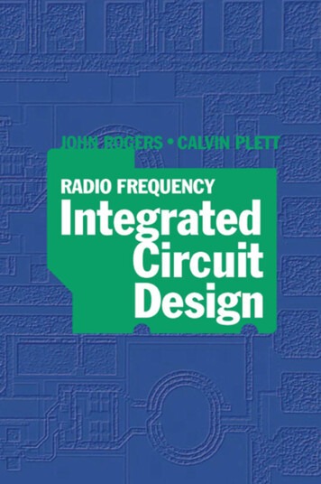
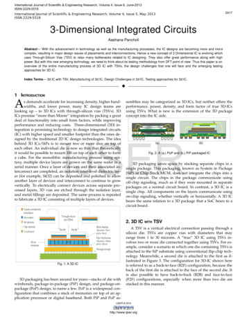
International Journal of Scientific & Engineering Research, Volume 4, Issue 6, June-2013ISSN 2229-55182417International Journal of Scientific & Engineering Research, Volume 4, Issue 5, May 2013ISSN 2229-55183-Dimensional Integrated CircuitsAashana PancholiAbstract— With the advancement in technology as well as the manufacturing processes, the IC designs are becoming more and mor ecomplex, resulting in major design issues of placements and interconnections. Hence a new concept of 3 Dimensional IC is evolving whichuses Through-Silicon Vias (TSV) to relax many bottlenecks related to IC designing. They also offer great performance along with highpower. But with this new emerging technology, we need to think about its testing methodology from DFT point of view. Thus this paper is anoverview of the entire manufactuting process of 3D IC with TSVs, the design challenges that one will face and the emerging testingapproaches for 3D IC.Index Terms— 3d IC with TSV, Manufacturing of 3d IC, Design Challenges in 3d IC, Testing approaches for 3d IC.—————————— ——————————1 INTRODUCTIONAs demands accelerate for increasing density, higher band widths, and lower power, many IC design teams arelooking up – to 3D ICs with through silicon vias (TSVs). 3DICs promise “more than Moore” integration by packing a greatdeal of functionality into small form factors, while improvingperformance and reducing costs. Three dimensional (3D) in tegration is promising technology to design integrated circuits(IC) with higher speed and smaller footprint than the ones de signed by the traditional 2D IC design technologies. The ideabehind 3D ICs/SiPs is to mount two or more dice on top ofeach other. An individual die is now so thin that theoreticallyit would be possible to mount 100 on top of each other to forma cube. For the monolithic manufacturing process using epi taxy, multiple device layers are grown on the same wafer in aserial manner. Once a layer of devices and their associated in terconnect are completed, an isolation inter level dielectric lay er (for example, SiO2) can be deposited and polished to allowanother layer of devices and interconnect to continue to growvertically. To electrically connect devices across separate pro cessed layers, 3D vias are etched through the isolation layer,and metal fillings are deposited. The same process is repeatedto fabricate a 3D IC consisting of multiple layers of devices.semblies may be categorized as 3D ICs, but neither offers theperformance, power, density, and form factor of true 3D ICsusing TSVs. What is new is the extension of the 3D packageconcept into the IC side.IJSER(a)(b)Fig. 2. A (a.) PoP and (b.) PiP packaged IC3D packaging saves space by stacking separate chips in asingle package. This packaging, known as System in Package(SiP) or Chip Stack MCM, does not integrate the chips into asingle circuit. The chips in the package communicate usingoff chip signaling, much as if they were mounted in separatepackages on a normal circuit board. In contrast, a 3D IC is asingle chip. All components on the layers communicate usingon chip signaling, whether vertically or horizontally. A 3D ICbears the same relation to a 3D package that a SoC bears to acircuit board.2. 3D IC WITH TSVFig. 1. A 3D IC3D packaging has been around for years—stacks of die withwirebonds, package in package (PiP) design, and package on package (PoP) design, to name a few. PoP is a widespread con figuration that combines a stack of memories on top of an ap plication processor or digital baseband. Both PiP and PoP as A TSV is a vertical electrical connection passing through asilicon die. TSVs are copper vias with diameters that mayrange from 1 to 30 microns. A “true” 3D IC using TSVs in volves two or more die connected together using TSVs. For ex ample, consider a scenario in which one die containing TSVs isattached to the SiP substrate using conventional flip chip tech nology. Meanwhile, a second die is attached to the first as il lustrated in Figure 3. The configuration for 3D IC shown hereis referred to as a back to face (B2F) configuration, because theback of the first die is attached to the face of the second die. Itis also possible to have back to back (B2B) and face to face(F2F) configurations, especially when more than two die arestacked in this manner.IJSER 2013http://www.ijser.orgIJSER 2013http://www.ijser.org
International Journal of Scientific & Engineering Research, Volume 4, Issue 6, June-2013ISSN 2229-5518International Journal of Scientific & Engineering Research, Volume 4, Issue 5, May 2013ISSN 2229-551824182.1 Manufacturing of 3d ICFig. 3. Back-to-Face Configuration of a 3D IC with TSVTSVs are a high performance technique used to create 3Dpackages and 3D integrated circuits, compared to alternativessuch as package on package, because the density of the vias issubstantially higher, and because the length of the connectionsis shorter. By using TSV technology, 3D ICs can pack a greatdeal of functionality into a small “footprint.” The differentdevices in the stack may be heterogeneous, e.g. combiningCMOS logic, DRAM and III V materials into a single IC. In ad dition, critical electrical paths through the device can bedrastically shortened, leading to faster operation.There are two main techniques of manufacturing a 3D ICIn terms of the process and the level of assembly that 3D ICsrequire, : Monolithic and Die Stacking .For the monolithic manufacturing process using epitaxy,multiple device layers are grown on the same wafer in a serialmanner. Once a layer of devices and their associated intercon nect are completed, an isolation inter level dielectric layer (forexample, SiO2) can be deposited and polished to allow anoth er layer of devices and interconnect to continue to grow vertic ally. To electrically connect devices across separate processedlayers, 3D vias are etched through the isolation layer, and met al fillings are deposited. The same process is repeated to fab ricate a 3D IC consisting of multiple layers of devices. There isonly one substrate, hence no need for aligning, thinning orbonding.Another 3D integration technique is to stack individual 2Ddie layers vertically. In contrast to monolithic 3D manufactur ing, which may require many changes in current process facil ities, fabricating 3D ICs using die stacking technology canminimize the impact of altering existing manufacturing tech nology and equipment. With 3D die stacking, the candidatedies to be integrated onto the same package can be designedand manufactured separately, just as they are with a regular,existing 2D planar process with additional manufacturing pro cesses of substrate thinning and through silicon via (TSV)filling, if needed. Then they are bonded together by precisealignment of inter die vias and the application of thermocom pression. In general, die stacking presents three integration al ternatives: wafer to wafer, die on wafer, and die on die, eachwith their respective pros and cons from a cost or yield per spective.IJSERTraditional single die SoCs have some disadvantages. Oneis that all components are placed on the same die at the sameprocess node, even though analog and RF design at advancedprocess nodes is extremely challenging. If a design team triesto implement analog circuitry at an advanced process node, itmay take a great deal of time to develop and test the necessaryIP blocks, as well as cope with process related issues such asvariability and leakage. Another challenge for single die SoCsis mixed signal integration and verification. Placing analogand digital circuitry in close proximity can cause many prob lems. Alternatively, sensitive analog or noisy digital compon ents could be placed in a separate IC, but that makes it neces sary to drive signals between individual packages, which con sumes power and reduces performance.2.2 Design Challenges for 3d ICIn a 3D IC, a silicon interposer substrate (either passive oractive) may be added to provide much finer die to die inter connections, thereby increasing performance and reducingpower consumption. A silicon interposer also includes TSVs,which provide connections from the upper metal layers to ad ditional backside metal layers.While 3D ICs with TSVs do not require a revolutionarynew 3D design system, they do require some new capabilitiesthat need to be added to existing tool sets for digital design,analog/custom design, and IC/package co design. 3D ICs re quire additional components to enable the 3D interconnec tions:1. Redistribution layers (RDLs) are typically formed on theback side of the die. Bumps can thus be placed on both thefront side and the back side.2. TSVs can be drilled between the first metal layer and theback side RDL. TSVs may have diameters from 1 to 5 microns.3. “Micro bumps” (much smaller flip chip bumps) have tobe aligned to create a data path from one die to another.Fig. 4. A complex 3D IC with TSV and Silicon InterposerFig. 5. Regular chip v/s. Chip with TSVIJSER 2013http://www.ijser.orgIJSER 2013http://www.ijser.org
International Journal of Scientific & Engineering Research, Volume 4, Issue 6, June-2013ISSN 2229-5518International Journal of Scientific & Engineering Research, Volume 4, Issue 5, May 2013ISSN 2229-5518Since many 3D stacks combine digital and analog/RF cir cuitry, a strong analog/mixed signal capability plus a robustIC/package co design capability and PCB layout system arecritical for providing a “complete” 3D IC realization methodo logy. Without an integrated approach to 3D IC design, optim izing system cost with the shortest possible turnaround timewill be challenging.In addition, new capabilities such as the following will beneeded to meet 3D IC design challenges: System level exploration 3D floorplanning 3D implementation (placement, optimization, routing) 3D extraction and analysis 3D design for test (DFT)3. TESTING APPROACHES FOR 3D ICIn traditional IC manufacturing, wafers are probed and in dividual dies tested (a process referred to as wafer sort) beforethey are packaged. In 3D integration, we are confronted withnew challenges before bonding wafers. The yield of 3D ICs canbe increased if we can bond pretested dies, or if we can sortthe wafers first and stack matched dies (based on the speed orpower consumption level) on top of each other. While wire bonded systems in package (SiPs) may have a few hundred in terconnects, 3D ICs may have thousands if not tens of thou sands of interconnects. Even a single defective TSV can renderan entire stack unusable. If individual TSVs have 99.9% yield,at least one defective TSV can be expected in a stack of 1,000TSVs.2419can be thrown away before it is placed in a package. If a pack age level test fails, the entire package would have to be thrownaway. Thus, wafer test is highly desirable, especially early inthe product lifecycle while defects may still be relatively high.But wafer test for 3D ICs is challenging for three reasons. First,today’s probe technology is unable to handle the finer pitchand dimensions of TSV tips, and is generally limited to hand ling several hundred probes, whereas the TSVs may have sev eral thousand probes. Second, probe technology leaves scrubmarks that can potentially cause problems with the down stream bonding step. Finally, wafer test requires the creation ofa known good die (KGD) stack. To stack known good die, thewafer must be thinned by about 75 percent so the tips of theTSVs can be exposed. However, as the thinned wafer is contac ted by a wafer probe, there’s a danger of damaging the wafer.3D ICs also introduce new intra die defects. These may beintroduced by new manufacturing steps such as wafer thin ning, or by bonding the top of a TSV to another wafer.Thermal effects are another potential sources of defects, be cause excessive heat may be generated from the denselypacked stack of dies. Thermo mechanical stress is caused bydifferent thermal coefficients of the various materials in thestack. Despite the differences in the manufacturing steps, theresulting faults (shorts, opens, delay defects) appear to be sim ilar to what we see in conventional ICs.IJSERA sound test methodology for 3D ICs is necessary for ICdesigners to have the confidence to design them and to enableper bond, midbond, post bond, and post package (final) test ing. Fortunately, solutions are starting to emerge. 3D IC testingcan leverage a large body of technology and experience withmodular SoC testing by using DFT wrappers and extendingthem to 3D testing. In the SoC world, modular testing is madepossible by DFT wrappers such as the IEEE 1149.1 boundaryscan standard and the IEEE 1500 embedded core test standard.For 3D IC testing, these wrappers need to be enhanced with3D specific extensions such as the following: Additional probe pads for pre bond testing Test “turnarounds” that start and finish the test accesspoints at the bottom side of each die Test “elevators” that propagate test data vertically throughthe stack.Like conventional single die IC test, 3D IC test must be con sidered at two levels – wafer test (for the silicon die), and pack age test (after die assembly into the package). The difference isthat in the 3D IC fabrication, there are many more intermedi ate steps, such as die stacking and TSV bonding. This providesmany more opportunities for wafer test before final assemblyand packaging.Modeling defects through TSV based interconnects is anew area. These defects may be introduced in the fabricationor the bonding of TSVs. Fortunately, defects introducedthrough TSVs can be mapped to existing fault models, such asopens, shorts, static, delay, and bridging faults. However, amethodology is needed to map TSV defects to known faulttypes.Fig. 6. Testing Approach to a 3D IC3.1 IEEE 1149.1 JTAG Test Approach for 3D ICIEEE Std 1149.1 standardizes a test wrapper for chips on aPrinted Circuit Board (PCB). It only has a serial mechanism,and lacks a higher bandwidth parallel test access mechanism.It has a two bit (or optional three bit) control port, consistingof the signals TCK, TMS, and optionally TRSTN. Internally, theadditional control signals are generated by stepping through a16 state finite state machine named TAP Controller.Wafer test is needed for cost optimization. If a die is bad, itIJSER 2013http://www.ijser.orgIJSER 2013http://www.ijser.org
International Journal of Scientific & Engineering Research, Volume 4, Issue 6, June-2013ISSN 2229-5518International Journal of Scientific & Engineering Research, Volume 4, Issue 5, May 2013ISSN 2229-55182420multiple active device layers are stacked together with directvertical interconnects, the TSVs.When moving from the 2D IC design to the 3D IC designdomain, there are several possible methods to connect the scanchain:Fig. 7. IEEE 1149.1 JTAG Wrapper for (a.) Conventional and (b.) 3D ICThe 3D enhancements are highlighted in orange and com prise the following four items:1. In order to support efficient high volume testing of thedie’s circuitry, a parallel, scalable test port of user definedwidth n is provisioned. We refer to the inputs and outputs ofthis port as resp. TPI and TPO.2. Test Turns in every die, that feed test data back to thepins in the bottom die3. There exist many alternative uses of IEEE 1149.1 beyondboard level interconnect testing for purposes like silicon andsoftware debug, emulation, in circuit programming, etc.Approach 1 (VIA3D): The simplest way is to perform 2D scanchain insertion and ordering for each layer separately, andthen connect N (N is the number of layers) scan chains intoone single scan chain by using N – 1 through silicon vias(TSVs) .Fig. 8 illustrates such an approach: Nodes 1, 2, and 3are connected to form a scan chain in layer 1; Nodes 4, 5, and 6are connected to form a scan chain in layer 2. A through silic on via (TSV, the solid line in the figure) is then used to connectthese two chains to be a single chain.Fig. 8. (a) A conceptual example of 3D IC which has 3 scan cells to beconnected. (b) VIA3D approach to connect each separate layer of scanchains via a single TSVIJSER3.2 Scan Chain Design for 3D ICIn VLSI circuit design, scan chains are introduced to im prove the testability of integrated circuits. After logic synthes is, all flipflops in the circuits are replaced with scan flip flops.These scan flip flops are connected sequentially to form a scanchain (or multiple scan chains) in a single chip. Each scan flip flop in the scan chain has two input sources: the output of theprevious flip flop in the scan chain and the output of the com binational circuits. During normal operation, the response atthe state outputs is captured in the flipflop. In testing mode,test vectors are shifted into the registers through the primaryinput pads and the test output values are shifted out throughthe primary output pads. The output values are comparedwith expected values to examine if the circuit is working cor rectly or not.Although the scan chain technique offers testing conveni ence, there is an area overhead coming from both multiplexeddata flipflop and the routing of the stitching wires. Longstitching wires connecting the output of each flip flop to theinput of the next flip flop increase the area of the circuit, makerouting difficult, and influence test performance as well. Sinceone of the main objectives in design for testability is to minim ize the impact of test circuitry on chip performance and cost, itis essential to minimize the wire length of a scan chain. Scanchain ordering techniques are used commonly in chip designto reduce wire length and circuit area. As technology scales,interconnect becomes the dominant source of delay and powerconsumption. Reducing interconnect delay and power con sumption has become a major concern in deep submicrondesigns. Three dimensional (3D) ICs are proposed as a prom ising solution to mitigate interconnect problems. In 3D chips,Advantage: Such an approach requires no change to thescan chain ordering algorithm: each layer is processed inde pendently, with a 2D scan chain ordering algorithm. The res ultant TSV number is minimized (N 1 TSVs for N layers).Disadvantage: Because it is a locally optimized approach, itmay result in the shortest scan chain for each layer, but thetotal scan chain length may not be globally optimized.We call this method to be VIA3D scan chain ordering sincethe number of through silicon vias is minimized.Approach 2 (MAP3D): Since the vertical distance between lay ers is small (in the range of 10 um to 100 um), the second meth od is to transform a 3D scan chain ordering problem into a 2Dordering problem, by mapping the nodes from several layersinto one single layer (i.e., (xi; yi;Li) is mapped to (xi; yi)). A 2Dscan chain ordering method is then applied to the design. Fig.9 illustrates such an approach. After mapping the top layernodes (Node 1, 2, and 3) onto the bottom layer, and performing2D scan chain ordering, the scan chain order is 4 1 5 2 6 3.Based on such scan chain ordering, in 3D design, if two con nected nodes are in different layers, a through silicon via (TSV)is used. In this example, there are 5 TSVs (the solid lines in thefigure).Fig. 9. Approach 2 (MAP3D): (a) All scan cells are mapped to 2D space.A 2D scan chain ordering method is then applied to the design. (b) Theordered connection is then done through TSVs.IJSER 2013http://www.ijser.orgIJSER 2013http://www.ijser.org
International Journal of Scientific & Engineering Research, Volume 4, Issue 6, June-2013ISSN 2229-5518International Journal of Scientific & Engineering Research, Volume 4, Issue 5, May 2013ISSN 2229-5518Advantage : Such an approach requires no change to thescan chain ordering algorithm: after mapping all the nodes toa 2D plane, a 2D scan chain ordering algorithm is applied. It isa global optimization method.Disadvantage : The vertical distance between layers is ig nored. It may end up to using many TSVs going back andforth between layers.We call this method to be MAP3D approach, because a 3Dscan chain ordering problem is mapped to be a 2D scan chainordering problem.Approach 3 (OPT3D): The third approach is optimal (OPT)3D ordering, from which we try to find the optimal solutionfor minimized wire length to form the scan chain. In this ap proach, the distance function includes horizontal cell to cellManhattan distance between cells as well as vertical distancebetween two layers. In such case, we cannot apply a 2D scanchain ordering algorithm directly. The data structure (for ex ample, the coordinates of a scan cell) may need to be modified.However, we take into account the 3D TSV effect (the length ofTSVs and the number of TSVs) in the optimization, and canhave full control of the optimization process: for example, wemay apply constraints on how many TSVs can be used duringscan chain ordering. Fig 10 illustrates such an approach.24214 ADVANTAGES OF 3D IC3 D integrated circuits were proposed invented to addressthe scaling challenge by stacking 2 D dies and connectingthem in the 3rd dimension. This promises to speed up commu nication between layered chips, compared to planar layout. 3DICs promise many significant benefits, including: FootprintMore functionality fits into a small space. This extendsMoore’s Law and enables a new generation of tiny but power ful devices. CostPartitioning a large chip into multiple smaller dies with 3Dstacking can improve the yield and reduce the fabrication costif individual dies are tested separately. Heterogeneous integrationCircuit layers can be built with different processes, or evenon different types of wafers. This means that components canbe optimized to a much greater degree than if they were builttogether on a single wafer. Moreover, components with incom patible manufacturing could be combined in a single 3D IC.IJSER Shorter interconnectThe average wire length is reduced. Common figures repor ted by researchers are on the order of 10 15%, but this reduc tion mostly applies to longer interconnect, which may affectcircuit delay by a greater amount. Given that 3D wires havemuch higher capacitance than conventional in die wires, cir cuit delay may or may not improve.Fig. 10. A OPT3D approach of connecting and ordering the scan chains tooptimize the minimum wire length.Advantage : Such an approach is a true 3D scan chain or dering optimization: the length of TSVs and the number ofTSVs are considered during optimization. Users have full con trol of the optimization process. It is a global optimizationmethod.Disadvantage : Modifications to 2D scan chain ordering al gorithms are needed before they can be applied.We call this method to be the OPT3D approach, because itis a true 3D scan chain ordering optimization approach.During 3D design, one of these methods can be chosen ac cording to the requirements, such as via number limitationsand the easiness to implement. For example, one may want toreserve as many TSVs as possible for signal routing or forthermal conduction, and choose the VIA3D approach. On theother hand, if minimizing scan chain length is more important,and one does not want to make the effort to change the 2Dscan chain algorithm, then the MAP3D approach can be adop ted. PowerKeeping a signal on chip can reduce its power consumptionby 10 100 times. Shorter wires also reduce power consumptionby producing less parasitic capacitance. Reducing the powerbudget leads to less heat generation, extended battery life, andlower cost of operation. DesignThe vertical dimension adds a higher order of connectivityand offers new design possibilities. Circuit securityThe stacked structure complicates attempts to reverse en gineer the circuitry. Sensitive circuits may also be dividedamong the layers in such a way as to obscure the function ofeach layer. Bandwidth3D integration allows large numbers of vertical viasbetween the layers. This allows construction of wide band width buses between functional blocks in different layers. Atypical example would be a processor memory 3D stack, withthe cache memory stacked on top of the processor. This ar rangement allows a bus much wider than the typical 128 or256 bits between the cache and processor. Wide buses in turnalleviate the memory wall problem.IJSER 2013http://www.ijser.orgIJSER 2013http://www.ijser.org
International Journal of Scientific & Engineering Research, Volume 4, Issue 6, June-2013ISSN 2229-5518International Journal of Scientific & Engineering Research, Volume 4, Issue 5, May 2013ISSN 2229-55185 DISADVANTAGES OF 3D IC YieldEach extra manufacturing step adds a risk for defects. In or der for 3D ICs to be commercially viable, defects could be re paired or tolerated, or defect density can be improved. HeatHeat building up within the stack must be dissipated. Thisis an inevitable issue as electrical proximity correlates withthermal proximity. Specific thermal hotspots must be morecarefully managed. Design complexityTaking full advantage of 3D integration requires sophistic ated design techniques and new CAD tools. TSV introduced overheadTSVs are large compared to gates and impact floorplans. Atthe 45 nm technology node, the area footprint of a 10 μm x10μm TSV is comparable to that of about 50 gates. Further more, manufacturability demands landing pads and keep outzones which further increase TSV area footprint. Dependingon the technology choices, TSVs block some subset of layoutresources. Via first TSVs are manufactured before metalliza tion, thus occupy the device layer and result in placementobstacles. Via last TSVs are manufactured after metallizationand pass through the chip. Thus, they occupy both the deviceand metal layers, resulting in placement and routing obstacles.While the usage of TSVs is generally expected to reduce wire length, this depends on the number of TSVs and their charac teristics.Also, the granularity of inter die partitioning impactswirelength. It typically decreases for moderate (blocks with20 100 modules) and coarse (block level partitioning) granular ities, but increases for fine (gate level partitioning) granularit ies.2422 Lack of clearly defined ownershipIt is unclear who should own the 3D IC integration andpackaging/assembly. It could be assembly houses like ASE orthe product OEMs.6 CHALLENGES TO IMPLEMENT 3D ICAlthough 3 D integration shows promise, significant chal lenges associated with efficient circuit design and operationhave hampered its adoption and further development. Themost important issue in 3 D IC is heat dissipation. The thermalproblem has already had an impact on the reliability and per formance of high performance 2 D ICs.The problem is aggravated in 3 D ICs, principally for tworeasons: the devices are more packed, which results in higherpower density; and the insulating dielectric layers between thedevice layers have much lower thermal conductivities than sil icon.Furthermore, the third dimension brings both flexibilityand difficulties to physical design algorithms. The existing 2 Dmetrics cannot be simply extended to generate similar metricsfor 3 D designs. Take wirelength as an example: a bounding cube'' might not have enough accuracy for wirelength estima tion because of the existence of huge obstacles in z direction.Also, a 3 D IC physical design problem is usually of highercomplexity, with a much enlarged solution space due to themultiple device layer structure. Efficient 3 D physical designstools, including 3 D floorplanning, placement and routingtools, are essential to 3 D IC circuit design.IJSER TestingTo achieve high overall yield and reduce costs, separate test ing of independent dies is essential. However, tight integrationbetween adjacent active layers in 3D ICs entails a significantamount of interconnect between different sections of the samecircuit module that were partitioned to different dies. Asidefrom the massive overhead introduced by required TSVs, sec tions of such a module, e.g., a multiplier, cannot be independ ently tested by conventional techniques. This particularly ap plies to timing critical paths laid out in 3D. Lack of standardsThere are few standards for TSV based 3D IC design, man ufacturing, and packaging, although this issue is being ad dressed. In addition, there are many integration options beingexplored such as via last, via first, via middle; interposers ordirect bonding; etc. Heterogeneous integration supply chainIn heterogeneously integrated systems, the delay of onepart from one of the different parts suppliers delays the deliv ery of the whole product, and so delays the revenue for each ofthe 3D IC part suppliers.7 ACKNOWLEDGEMENTI would like to indeed thank my mentors and guide Mr.Arif Makrani at eInfochips, Ahmedabad, my M.tech mentorand External Guide Mr. Nirav Nanavati from eInfochips,Ahmedabad and Mr. Bhavesh Soni my M.Tech internal guidefrom UVPCE, Ganpat University for inspiring and guiding metowards this research topic. Its a survey paper and the contentsof this paper by me is an overall survfey done on different pa pers already published and articles found on this subject.Hence I also want to acknowledge heartily each and every au thor who has done this research and helped me understandthe concepts related to my survey paper.8[1][2][3][4][5]ReferencesSystem Level Comparison of Power Delivery Design for 2D and 3DICs, Nauman H. Khan, Syed M. Alam*, and Soha Hassoun, in 3D Sys tem Integration, 2009. 3DIC 2009. IEEE International Conference,Sept. 20093D IC Design: The Challenges of 2.5D versus 3D, Samta Bansal, EE Times Design Article, Sept. 20113D TSV Test: ATE challenges and potential solutions, Ben, Scott, Kar en, Andy, Robert, and Erik, EETimes Design Article, Oct 2011Design tools for 3D ICs remain a challenge, Ron Wilson, ElectronicsBlog on Embedded.com, June,2011Test Challenges for 3D Integrated Circuits, Hsien Hsin S. Lee &Krishnendu Chakrabarty,IJSER 2013http://www.ijser.orgIJSER 2013http://www.ijser.org
International Journal of Scientific &
3-Dimensional Integrated Circuits Aashana Pancholi Abstract— With the advancement in technology as well as the manufacturing processes, the IC designs are becoming more and more complex, resulting in major design issues of placements and interconnections.