Transcription
Control ValveSourcebook —Refining
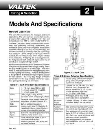
1IntroductionRefineryControl ValvesThe petroleum refining industryis an industry that is most vitalto our modern global economy.Almost constantly, you are inclose contact with productsthat once were distilled throughcolumns like those shown on theleft. Some of these materials andproducts are so important thattheir rapidly fluctuating marketvalues are reported every day ontelevision, radio, Internet, andnewspapers.The products go through manyphases from crude oil and otherraw materials to the final productsyou use every day. On thefollowing page is a chart showing.
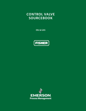
Figure 1.1.1. Complete RefineryE1445DESALTERCRUDE OILSTORAGEATMOSPHERIC CRUDE TEDGAS PLANTSATURATEDGAS PLANTDA BOTTOMSDAOHYDROGENVACUUM GAS OILCOKER GASVISBREAKERVACUUM OKER GAS OILFEEDHYDROTREATINGHYDROGENC3 C4 MENTALKYLATION RIC GAS OILDIESELKEROSENE/JETNAPTHALIGHT STRAIGHT RUN GASOLINEBUTANE AND LIGHTERCOKER NAPTHACOKER DIESELPETROLEUM COKEDIESEL/JETHC NAPHTHAFCC GASOLINELIGHT CYCLE OILDECANTED NGSULFURRECOVERYHYDROTREATERHYDROGENSULFIDELIGHT STRAIGHT RUNISOMERATETREATINGAMINETREATINGTAIL GASUNITGASOLINE BLENDING1-2RESIDUALBLENDINGDISTILLATE BLENDINGSOUR FUEL GASPETROLEUMCOKEASPHALTSHEAVY FUEL OILNO. 2HEATING OILDIESEL FUELSKEROSENEJET FUELLOW LIQUIFIEDPETROLEUMGAS (LPG)SULFURREFINERYFUEL GAS1 - Introduction
1 - Introductionthe raw materials, some of the intermediate petroleumproduct phases, and some of the final products that reachyou as a consumer. Many of the products on the next pageare further processed and become part of too many items tomention.Valve SelectionThe products are all processed and made ready for themarket in refineries. Efficient operation of refineries has atremendous impact on profit, final consumer price, and wiseuse of limited resources. Efficient refinery operation dependson well-planned and well-executed control strategies,responsive control systems, and tough, reliable controlvalves.Since every refinery is different in its unit makeup and thetechnologies it utilizes, the control valve requirements andrecommendations presented by this sourcebook should beconsidered as general guidelines.This sourcebook is a primer on the use of control valves inmany refining processes. It is intended to help you: Understand the types of refining processes, Learn where control valves are typically located withinthe process, Identify the operational problems that might be causedby poor valve performance, Identify Fisher valves that are commonly used for theapplications in a refinery.A standard format is used to present the information on eachrefining process. The information provided is: Other commonly-used names for the described process The basis (feed rate) for the example process A short description of the process A list and description of each important process valve inthe unit A functional drawing of the process Typical process conditions Names of Fisher valves that can be considered for eachprocess Potential process impacts and special considerations foreach valveOther NamesIt is not possible to make an all-inclusive list of commonlyused process names. Many refineries have developed specificprocess names based on local preference or the preferencesof the licensor or designer that developed the process.Process DescriptionsMany processing units within a refinery contain furnacesand distillation columns, which makes these pieces ofequipment and their operation fairly universal. The valverequirements for these units are presented in Chapters 1 and2, respectively, and are not repeated in the chapters thatfollow.Chapters 3 through 5 discuss refining processes, with thevalve information presented in each chapter applying directlyto the specific process being described.The information presented in this sourcebook is intendedto assist in understanding the control valve requirements ofgeneral refining processes.The information in this sourcebook is intended to assist withunderstanding general refining process requirements andgeneral control valve considerations.Under no circumstances should this information alone beused to select a control valve without ensuring that theproper valve construction is identified for the application andprocess conditions.All valve considerations should be reviewed with yourEmerson sales office or representative as part of any valveselection or specification activity.Control ValvesValves described within a chapter are labeled and numberedcorresponding to the identification used in the process flowchart for that chapter. The order in which they are discussedis from left-to-right and top-to-bottom.If a valve is controlling feed, intermediate or final productstreams, the U.S. dollar value of that stream (as recorded atthe time of sourcebook publication) and typical feed rateare provided. The valve function also is described, and aspecification section gives added information on processconditions, names of Fisher valves that can be considered,process impact of the valve and any special considerations.Process DrawingThe process drawing within each chapter shows majorequipment items, their typical placement within theprocessing system and process flow direction. Utilities,pumps and most heat exchangers are not shown. Valves arenumbered in sequence from left-to-right and top-to-bottom.Problem ValvesOften there are references to valve-caused problems ordifficulties. The litany of problems includes valve stickinesscaused by excessive friction (called “stiction”), excessive playin valve-to-actuator linkages (typically in rotary valves) thatcauses deadband, excessive valve stem packing leakage,and valve materials that are incompatible with the flowingmedium. Any one or a combination of these difficultiescan affect process quality and throughput, with a resultingnegative impact on refinery profitability.Many of these problems can be avoided or minimizedthrough proper valve selection. Consideration should begiven to valve style and size, actuator capabilities, analog vs.digital instrumentation, materials of construction and thelike. Although not being all-inclusive, the information thatthis sourcebook provides should facilitate the valve selectionprocess.1-3
2Fisher Product Toolsand DocumentationIn the day-to-day operation ofyour plant you have a long list ofconcerns, like meeting productionschedules, maintaining productquality, and improving theefficiency of plant utilities, toname just a few. The last thingyou should have to worry about isthe performance of your plant’scontrol valves.Serving You for the Life ofYour PlantFor nearly 40 years, Emersonhas been a provider of trustedexpertise for reliability centeredcontrol valve maintenance.A network of service centers,manufacturing sites, and salesrepresentatives puts experiencedprofessionals where and whenthey are needed. . .
2 - Fisher Tools and DocumentationContact your local sales office to get in touch with the ServiceCenter nearest you. Highly skilled technicians provide costeffective maintenance, valve reliability, and increased processavailability through flexible, local service.ManufacturingOne thing all control valve buyers have in common is adesire to know as much as possible about their prospectivepurchase and the company that manufactures it. Fisher valveoperations started in 1880 in Marshalltown, Iowa, UnitedStates. Since then, the company has grown to more than8,000 people worldwide. Emerson is the largest control valveand regulator manufacturer in the world.To meet local product and delivery needs, Fisher productmanufacturing plants are located in each world area. Eachmanufacturing site is tied directly to Fisher product designcenters via the latest communication links, helping ensurethat manufacturing operations utilize the most up-to-dateproduct information. This means that each Fisher productmeets design specifications and performs as intended,regardless of where it’s individual or component parts weremanufactured.Design Verification through Lab TestingEmerson engineers conduct tests that analyze cavitation,materials, fatigue, wear, high and low temperatures, valveactuators, loop variability, leakage, hydrostatic forces,gaskets, seals, and control system compatibility. In the2-2controlled lab environment, special tests are also commonlyperformed to solve customers’ toughest challenges.Results from flow variability testing, hydrostatic pressuretesting, capacity verification, metallurgical development, andcycle life testing all lead to one conclusion—the valve meetsor exceeds the demanding requirements established by theprocess control industry.Emerson Innovation CenterThe Emerson Innovation Center for Fisher Technology inMarshalltown, Iowa, USA, is home to the world’s largestflow lab used to evaluate control valves. It incorporates flowtesting capabilities up to NPS 36 and 240 bar (3,500 psig).Final control elements are tested in conformance to IECand ISA standards in real-world plant conditions to ensureproduction reliability, efficiency, environmental compliance,and safety.Application AssistanceControl valves are an investment, so you want to speakwith someone one-on-one who knows about you andyour business. The Emerson sales network has extensiveapplication experience and can recommend the mostsuitable products for your application. Go towww.Fisher.com and click on Fisher Sales Contacts to findthe sales office nearest you. Because of the technical natureof the Fisher product line, most of the Emerson networkare engineers with substantial factory training. At Emerson,
2 - Fisher Tools and DocumentationLab TestedOur control valves have undergone thoroughand extensive testing. Test engineers determinesizing coefficients, stem force requirements, andinvestigate actual performance.we’ve built our reputation not just on our quality Fisherproducts, but also on our people and their dedication toservice. Wherever you are, there’s an Emerson salesperson todiscuss your control needs.health, areas of potential risks, and a prioritized recommendaction plan.OEM Replacement PartsToday, the need for training is more critical than ever toachieve and maintain cost-effective process operations. Sowhether it’s at your site, our site, or the website, we workhard to ensure you know how to get the best from yourFisher products through a selection of valve and instrumenttraining courses. Emerson offers comprehensive customertraining and education programs that cover a wide range ofprocess topics. The programs consist of structured coursesthat are geared to real-world situations. Customer trainingis provided at our educational facilities located near you. Inaddition to standard programs, tailored courses designedfor the specific needs of an organization can be conductedon-site. Prepackaged training courses are available in videoformat, making selftraining convenient and cost-effective.www.EmersonProcess.com/EducationThe Emerson manufacturing network supports Fisher partsneeds in any emergency. The integrated sales channel andbusiness partner networks offer a local point of customercontact with delivery of process control applicationknowledge and complimentary capabilities. Flexibledeployment of highly skilled, factory-trained Emersontechnicians strategically located near customer processplants provide repair capabilities for all types of control valvesand associated field instruments. Emerson’s comprehensivequick ship programs, along with a supporting distributionnetwork of process control products and spare parts,guarantee immediate response to customer needs.Diagnostic ServicesWhen precision is critical to keep your process in peakperformance, you need your valves to perform to industryand factory specifications. Emerson’s skilled, certified fieldtechnicians carefully analyze control valves using diagnosticservices to identify maintenance priorities and develop aproactive plan detailing when devices should be repaired orreplaced with next generation technologies. After diagnosticservice, technicians produce a clear report indicating assetTrainingSizing and SpecificationFisher Specification Manager software is available throughyour local salesperson. The software offers a powerful setof tools for quickly producing an ISA specification sheet,improving noise prediction calculations and exportingdimensional data for Fisher and Baumann control valves.You’ll find it easy to learn and use.2-3
2 - Fisher Tools and DocumentationPRECISE ACTUATIONLOW-EMISSIONS PERFORMANCEHIGH-CYCLE TESTINGAntisurge valves must be responsivein order to protect critical and costlycompressors from damage duringtransients. Fisher precision actuationtechnology enables a full stroke up to50.8 cm (20 inches) in less than onesecond and better than 1% positioningaccuracy.Fisher ENVIRO-SEAL low emissionspacking is designed and tested for Fishercontrol valves to keep fugitive emissionsbelow 100 parts per million volume(ppmv) in your throttling application fortens of thousands of cycles.Many of Emerson’s standard Fisherproducts are used in extremely highcycle applications, and must be testedto more than one million cycles. Thosesame standard products are used inyour refinery to enhance reliability.WITHSTANDING VIBRATIONREDUCING PROCESS VARIABILITYQUIETING NOISEFisher control valves are designedand tested for robustness in vibrationapplications. They are subjected toadditional testing for millions of cycles attheir resonant (worst case) frequency toenhance performance in your facility.Fisher control valve assembliesare subjected to on-line, dynamicperformance testing to evaluatetheir ability to reduce your processvariability. These tests replicate howcontrol valves are used in your plant.Supported with a 4,738 m2 (51,000 ft2)facility and a unique 2, 415 m2 (26,000ft2) sound chamber, Emerson can quantifynoise from valves, piping, and vents.This capability provides insight to ensurehighly accurate noise prediction andhelps you comply with regulatory (IEC)requirements.2-4
2 - Fisher Tools and DocumentationOther ResourcesFisher Control Valve HandbookThe Control Valve Handbook is both a textbook and areference on the strongest link in the control loop: thecontrol valve and its accessories. This book includes extensiveand proven knowledge from leading experts in the processcontrol field including contributions from the ISA and theCrane Company.The Fisher Story—125 Years of Process ControlExperienceThis book is a compilation of photos, heritage items,memories, facts and experiences from the first 125 years.2-5
2 - Fisher Tools and DocumentationSlidingStemControlValvesWe have the broadestUNIVERSALrange of sliding-stemcontrol valves available anywherein a variety of constructionmaterials, flow characteristics, andend connections. Complementaryactuators and accessories arealso available. Popular sliding-Baumann valves.Fisher easy-e valve line popularizedthe concept of one valve body withinterchangeable trim. Can be usedeffectively, plantwide, in a number ofapplications.HIGH PRESSURE, HIGH FLOWSTEAM CONDITIONINGBuilt-to-last design with rugged cageguiding and hardened trim materials.Fisher ENVIRO-SEAL and HIGH-SEALpacking systems in the valve provide atight stem seal for fugitive emissionscontrol.Enhanced pressure reduction capabilitiesas well as highly efficient and accuratesteam conditioning performance ina single valve. Provides the ultimatecombination of performance andmaintainability.stem valve product lines include:Fisher easy-e globe valves and2-6
2 - Fisher Tools and DocumentationCHEMICAL AND GENERAL SERVICEUTILITY AND LOW FLOW SERVICESANITARYUnmatched innovation, technology, andreliability. Compact size, anti-corrosionfinish, certified emission control packingand integrated digital technology.Compact, low-weight Baumann controlvalves help ensure reduced installationand maintenance costs. Designs includepatented low flow technology andexceptional deadband and hysteresischaracteristics.Designed to satisfy the stringentdemands of the pharmaceutical andbiotechnology industries. Includes FDA,USP CLVI, and 3A Sanitary Standards,Inc. certifications.ENVIRONMENTAL REQUIREMENTSSWEET OR SOUR OIL ANDGAS APPLICATIONSHIGH-PRESSURE GAS SERVICEFisher ENVIRO-SEAL valve packingsystems are designed to controlemissions below 100 ppmv. Provideextended service life.Special deep-bore hammer nut forincreased safety. Fisher Micro-Formvalve plug is sour gas compatible.Fisher easy-Drive electric actuator wasdesigned to protect the environmentfrom methane gas venting.Innovative Fisher FloPro selectable flowrate feature. Designed for high-pressureseparators, scrubbers, and other gasprocessing equipment.2-7
2 - Fisher Tools and DocumentationRotaryControlValvesWhen capacity andPROVEN PERFORMANCEperformance are therequirements, the Fisher line ofrotary valves is the answer. Popularrotary valve products include ball,eccentric disc, eccentric plug, andbutterfly valves with such familiartradenames as Vee-Ball andControl-Disk. 2-8Fisher Vee-Ball control valves featurethe Fisher-pioneered V-notch ball fornonclogging, high capacity flow control.Designed for gas, steam, liquids andfibrous slurries where reducing processvariability is a must.HARD-TO-HANDLE FLUIDSHIGH PERFORMANCEFisher V500 and CV500 control valvesoffer low operating torque and combinethe ruggedness of a globe valve with theefficiency of a rotary valve. Well suited toerosive, coking and other hard-to-handlefluids.Fisher 8580 control valves are reliable,high performance butterfly valvessuitable for throttling applications thatrequire extremely low leakage rates.
2 - Fisher Tools and DocumentationWIDE CONTROL RANGEPIPELINE CONTROLFisher Control-Disk valves have awide control range and offer excellentthrottling performance to control closerto target set point, regardless of processdisturbances.Designed from the ground up withfeatures for optimized pressure, flow,and process control. Used in gas and oilflow streams. Special Fisher Aerodomeor Hydrodome attenuators reducenoise and cavitation effects that causepipeline vibration.TIGHT SHUTOFFAUTOMATED ON-OFFPERFORMANCEFisher high performance valves survivein extreme pressure and temperatureconditions. Exceptional shutoff rateswith birdirectional soft seal ring. SpecialFisher NOVEX and Phoenix III metal sealsoffer added shutoff capabilities.Fisher 8580 rotary valves withFieldQ rack-and-pinion actuatorsoffer automated on-off, quarter-turnperformance and feature either a soft ormetal seal for enhanced shutoff.2-9
2 - Fisher Tools and DocumentationFieldInstrumentsand ValveAccessoriesAwide selection of FisherDIGITAL VALVE CONTROLLERdigital, pneumatic andelectronic instruments control valveposition and variables such as level,pressure, or temperature. PopularFisher products include:FIELDVUE digital valve controllers,FIELDVUE digital level transmitters,ValveLink software, and pressureand temperature controllers.2-10The Fisher FIELDVUE digital valvecontroller family has powerful diagnosticcapabilities. Patented modular design andminor loop feedback.DIGITAL VALVE CONTROLLERVALVE DIAGNOSTICS SOFTWARENon-contact, linkage-less travel feedbackand local user interface with LCD andfour pushbuttons for menu navigation.Powerful FIELDVUE diagnostic capabilities.ValveLink software is the configuration,calibration, and diagnostic tool usedwith FIELDVUE Instrumentation. It usespredictive intelligence to improve theavailability and performance of controlvalves.
2 - Fisher Tools and DocumentationWIRELESS POSITION MONITORDIGITAL LEVEL TRANSMITTERPRESSURE CONTROLLERRugged, reliable, easy-to-usemeasurement device that monitorsequipment position with a percent of spanplus on/off indication.Provides installation flexibility. Built-to-lastdesign. HART and FOUNDATION fieldbuscertified, bringing digital advantages toliquid level control.Offers long-lasting dependability. Simplyconstructed. Can reduce steady-state air/gas consumption to as little as 1/10th thatof other products.ELECTRO-PNEUMATICTRANSDUCERLIQUID LEVEL CONTROLLERVOLUME BOOSTERSpecial free-flow design resists plugging.Approved for use with natural gas as thesupply medium.Designed for controlling level on gasseparators and scrubbers. Sour gas serviceready. Low bleed relays conserve energyand reduce impact on the environment.Used in conjuction with a positioner ona throttling control valve to increasestroking speed. Connectors and piping canbe installed for diagnostic testing.2-11
2 - Fisher Tools and DocumentationSevereServiceSolutionsFor decades, we have beenCAVITATING LIQUIDproviding solutions forsevere service control valveapplications in the power andhydrocarbon industries. Specialcontrol problems—eitheranticipated or existing—thatinvolve extremes in temperature,pressure, corrosion, erosion,a Fisher valve solution.Cavitrol III trim contains a multitudeof specially shaped holes that reduceflow turbulence. The holes are radiallyaligned to flow from one restriction toanother. Both features dissipate thefluid pressure and prevent cavitation.OUTGASSINGDRILLED HOLE NOISE TRIMDirty Service Trim for Outgassing (DST-G)is used in services where the fluid hasdissolved gases that are released fromsolution due to a reduction in pressure.DST-G trim allows large 6.35 mm (¼-inch)particulate to pass.Whisper Trim III is a drilled hole trimavailable in a variety of control valvesizes and styles. It delivers excellentnoise reduction. The design architectureeven allows for flexibility of size,pressure class, materials, rangeability,and attenuation.noise, flashing or cavitation, have2-12
2 - Fisher Tools and DocumentationCAVITATING DIRTY FLOWCAVITATING DIRTY FLOW,CUSTOMIZEDLARGE PRESSURE DROPSNotchFlo DST trim uses a series offlow restrictions and expansions tocontrol the pressure drop of the fluid.The notched plug allows up to 12 mm(½-inch) particulate to flow through thetrim without plugging.Dirty Service Trim (DST) providescavitation-control for applicationswith entrained particulate. It uses acombined axial and radial flow paththat features large openings allowingparticulate up to 19 mm (¾-inch) indiameter to pass through the valve.Each of the Cavitrol IV trim stages has asuccessively large flow area. The resultsis very efficient operation because morethan 90 percent of the overall pressuredrop is taken in the initial stages wherethere is little danger of cavity formation.STACKED DISK NOISE TRIMSLOTTED NOISE TRIMDIFFUSERSWhisperFlo trim offers state-of-theart noise attenuation in vapor, gas,or steam applications involving highpressure drops. It is a laser cut, stackeddisk cage assembly that is available inglobe and angle bodies for the mostsevere applications.Whisper Trim I offers provenattenuation of aerodynamic noisein vapor, gas, or steam applicationsinvolving low to medium pressure drops.It offers economical, dependable noiseattenuation. It offers great applicationflexibility.The 6010 inline diffuser places backpressure on the control valve, therebyreducing the turbulence and pressuredrop across the valve, which are maincontributors in damaging noise andvibration.2-13
3Available TechnologiesThis section will go throughavailable Fisher technologiescommonly used in the refiningindustry.TopicPage3.1Sliding-Stem Valves. . . . . . . . . . . . . . . 3-23.2Rotary Valves. . . . . . . . . . . . . . . . . . . 3-43.3Actuators . . . . . . . . . . . . . . . . . . . . . 3-53.4Control Valve packing . . . . . . . . . . . . . 3-83.5Positioners . . . . . . . . . . . . . . . . . . . 3-113.6Levels . . . . . . . . . . . . . . . . . . . . . . 3-12
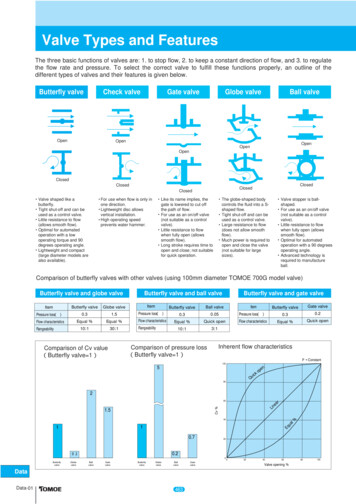
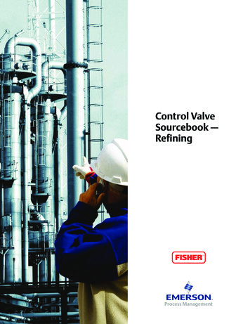
3 - Available Technologies3. Control ValvesThe control valve regulates the rate of fluid flow as theposition of the valve plug or disk is changed by force from theactuator. To do this, the valve must: Contain the fluid without external leakage Have adequate capacity for the intended service Be capable of withstanding the erosive, corrosive, andtemperature influences of the process Incorporate appropriate end connections to mate withadjacent pipelines and actuator attachment means topermit transmission of actuator thrust to the valve plugstem or rotary shaftMany styles of control valve bodies have been developedthrough the years. Some serve a wide application range;others meet specific service conditions and are used lessfrequently. The following chapter describes control valvebodies and trim styles.35A7592-EW7027-3Figure 3.1.1. Single-Ported Globe-Style Valve Body3.1 Sliding-Stem ValvesUnbalanced Single-Port ValveConstructionsSingle-port is the most common valve body style and issimple in construction. These valves are available in variousforms, such as globe, angle, and split constructions.Generally, single-port valves are specified for applicationswith stringent shutoff requirements. They use metal-tometal seating surfaces or soft-seating with PTFE or othercomposition materials forming the seal. Single-port valvescan handle most service requirements.Because high-pressure fluid is normally loading the entirearea of the port, the unbalance force created must beconsidered in selecting actuators for single-port control valvebodies.Although most popular in the smaller sizes, single-portvalves can often be used in NPS 4 to NPS 8 with high-thrustactuators.Many modern single-seated valve bodies use cage or retainerstyle constructions to retain the seat ring, provide valve-plugguiding, and provide a means for establishing particular valveflow characteristics. Retainer-style trim also offers ease ofmaintenance with flow characteristics altered by the plugcontour. Cage or retainer-style single-seated valve bodiescan also be easily modified by changing trim parts to providereduced-capacity flow, noise attenuation, or reduction orelimination of cavitation.Figure 3.1.1 shows two styles of single-ported or singleseated globe-type control valve bodies. They are widely usedin process control applications, particularly in sizes from NPS1 through NPS 4.Angle valves are typically single-ported (figure 3.1.2).Normal flow direction is up through the seat ring. They arecommonly used in boiler feedwater and heater drain serviceand in piping schemes where space is at a premium and thevalve can also serve as an elbow. The valve shown has cage3-2W0971-3Figure 3.1.2. Angle-Style Valve Bodystyle construction. Others might have screwed-in seat rings,expanded outlet connections, restricted trim, and outletliners for reduction of erosion damage.High pressure, single-ported globe valves are often usedin refineries. Variations available include cage-guided trim,bolted body-to-bonnet connection, and self-draining angleversions.Flanged versions are available with ratings to ASME CL2500and greater.Balanced-Plug, Cage-Style ValveConstructionsThis single-ported valve body style uses one seat ring andprovides the advantages of a balanced valve plug often
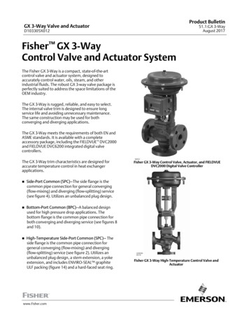
3 - Available TechnologiesW0997-2Figure 3.1.4. Expanded End Connection Valve with NoiseAbatement TrimW0992-3Figure 3.1.3. Balanced-Plug, Cage-Style Valve Constructionassociated only with double-ported valve bodies (figure3.1.3.). Cage-style trim provides valve plug guiding, seatring retention, and flow characterization. In addition, a sealbetween the upper portion of the valve plug and the wallof the cage cylinder virtually eliminates leakage from theupstream to downstream pressures. Downstream pressureacts on the top and bottom sides of the valve plug, therebyreducing the static unbalance force. Reduced unbalanceforce permits operation of the valve with smaller actuatorsthan those necessary for conventional single-ported valvebodies. Interchangeability of trim permits choice of severalflow characteristics, noise attenuation, or anti-cavitationcomponents. For most available trim designs, the standarddirection of flow is in through the cage openings and downthrough the seat ring. These are available in various materialcombinations, sizes beyond NPS 36, and pressure ratings toCL 2500 and greater.Expanded End Connection, Cage-GuidedValve ConstructionsW0467-1aThis adaptation of the cage-guided valve bodies mentionedabove was designed for noise applications such as highpressure gas reducing stations where sonic gas velocitiesare often encountered at the outlet of conventional valvebodies (figure 3.1.4). The design incorporates oversizedend connections with a streamlined flow path and theease of trim maintenance inherent with cage-styleconstructions. Use of noise abatement trim reduces overallnoise levels by as much as 40 decibels (dB). Flow directiondepends on the intended service and trim selection, withunbalanced constructions normally flowing up and balancedconstructions normally flowing down.Figure 3.1.5. Double-Ported Globe-Style Valve BodyPort-Guided Single-Port ValveConstructionsValve bodies are usually furnished only in the larger sizes—NPS 4 or larger and bodies normally have higher capacitythan single-ported valves of the same line size. Many doubleported bodies reverse, so the valve plug can be installed aseither push-down-to-open or push-down-to-close (figure3.1.5). Metal-to-metal seating usually provides only Class IIshutoff capability, although Class III capability is also possible.These valve bodies are usually limited to 10 bar (150 psig)maximum pressure drop. They are susceptible to velocityinduced vibration. Port-guided single-port valve bodies aretypically provided with screwed in seat rings which might bedifficult to remove after use.Double-Ported Valve ConstructionsDynamic force on the plug tends to be balanced as flow tendsto open one port and close the other. Reduced dynamicforces a
on well-planned and well-executed control strategies, responsive control systems, and tough, reliable control valves. This sourcebook is a primer on the use of control valves in many refining proc