Transcription
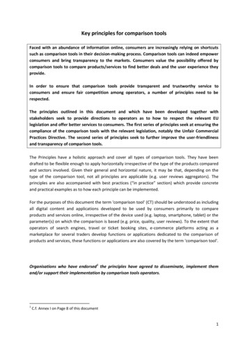
ContentsPrintA COMPARISON STUDY OF THE COMMUTATION METHODS FORTHE THREE-PHASE PERMANENT MAGNET BRUSHLESS DC MOTORShiyoung Lee, Ph.D.Pennsylvania State University Berks CampusRoom 120 Luerssen Building, Tulpehocken RoadReading, PA 19610-6009Tom Lemley, General Manager,Gene Keohane, Director of EngineeringMoog Inc., Components Group750 West Sproul RoadSpringfield, PA 19064Abstract: The three-phase permanent magnetbrushless dc (BLDC) motor inherently needs anelectronic commutation circuit to drive it because it isnot a self-commutating motor. It is contrary to theconventional brush motor which commutates itself.This paper presents a comparison study of threewidely used different commutation methods in termsof the complexity of the commutation circuit, torqueripple, and efficiency. The principle of the operation ofthe three-phase BLDC motor is introduced first andthen three commutation strategies – trapezoidal (sixstep), sinusoidal and field oriented control (FOC) - arediscussed in detail. The characteristics of the threecommutation methods are investigated intensely, andthe advantages and disadvantages of each arecompared to the others. The second generationMC73110 motor control chip from PerformanceMotion Devices, Inc. is used for experimentalverification of three different commutation strategies.It makes possible to control the BLDC motor withtrapezoidal commutation with Hall-effect positionsensor. The sinusoidal commutation with encoderposition feedback and the FOC with either Hall orencoder position feedback signal are also achievable.The experimental motor waveforms and torqueripples with different commutation methods arefurther investigated.I. INTRODUCTIONThe BLDC motor is a rotating electric motor consisting ofthree-phase armature windings on the stator andpermanent magnets on the rotor, as shown in Figure 1.The mechanical structure of the BLDC motor is theconventional permanent magnet brushed dc motor(PMDCM) inside out; the rotor contains permanent(BLDC Motor: Moog BN23-28PM-01LHE )(PMDCM: Moog AS-790D-501)Fig. 1 Comparison of BLDC motor and PMDCM structures(Courtesy of Moog Inc., Components Group)magnets and the motor windings are mounted on thestator. The BLDC motor does not have brushes; those arerequired for commutation of PMDCM. Therefore, themaintenance-free motor drive system is possible withBLDC motor. The permanent magnets on the rotor of theBLDC motor provide a constant rotor magnetic field, andmakes possible a highly efficient, high torque-pervolume, and low moment of inertia motor [1].The BLDC motor is an electronically commutatingpermanent magnet DC motor [1]. Because of this motor’sinherent variable speed drive nature, its applications aregrowing, such as its use in white goods, automobile, andmachine building industries. The commutation circuit for
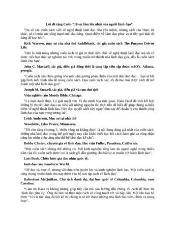
ContentsPrintthe three-phase BLDC motor can be implemented withdiscrete components or a dedicated control integratedcircuit (IC). The design with discrete componentsprovides many insights on the commutation circuit toengineers; at the same time, it requires lots of time andeffort for building hardware and troubleshooting. Thededicated IC approach looks promising since little or noadditional circuitry is required. Some manufacturers evenoffer dedicated setup software to use their IC.In this paper the characteristics of three differentcommutation strategies are investigated and theexperimental waveforms are demonstrated with theMC73110-based BLDC motor controller. The same motorand control electronics has been used to compare theperformances of the system in three different modes ofcommutation.The typical three-phase BLDC motor drive consists of apower stage with a three-phase full-bridge scheme asshown in Figure 2 and a controller that should providethree-phase PWM signals based on three Hall-effectsensors or an encoder or a resolver for the positionfeedback.There are two types of permanent magnet brushless dcmotors, which depend on their back-EMF waveforms.The BLDC motor has the trapezoidal (six-step) backEMF (electromotive force) waveform. The one withsinusoidal back-EMF is called PMSM (PermanentMagnet Synchronous Motor).Table 1. Comparison of BLDC and PMSMWinding DistributionEnergized PhaseBack-EMF WaveformTorque StrengthBLDCTrapezoidalTwo PhasesTrapezoidalStrongPMSMSinusoidalThree PhasesSinusoidalWeakA simplified three-phase full-bridge power circuit forBLDC motor is shown in Figure 2. The relationshipsbetween three-phase back-EMF, motor current, and airgap power of the BLDC motor are shown in Figure 3 [2].The trapezoidal back-EMF (ea, b, and c) has a constantmagnitude of Ep during 120 electrical degrees in bothpositive and negative half cycle. The air-gap power, Pa,and the electromagnetic torque are both continuous whenapplying motor current ia, b, and c during the same period inboth half cycles.The instantaneous voltage equation and torque equationsof a BLDC motor from Figures 2 and 3 are [1]Figure 2. Three-phase full-bridge power circuit for BLDC motor driveThe PMSM provides nearly zero torque ripples, whichgives higher efficiency. The BLDC motor has 15% morepower density than PMSM, assuming the copper lossesare equal for both motors and the PMSM has unity powerfactor. For the same torque, the PMSM requires highercurrent handling capability [1].The stator winding of BLDC motor is typicallytrapezoidally wound in order to generate the trapezoidalshape back-EMF waveform. The generated torque has aconsiderable torque ripple which occurs at each step ofthe trapezoidal (or six-step) commutation. The six-stepcommutation typically energizes two motor phasewindings at any commutation sequence. On the contrary,the PMSM has sinusoidally distributed winding toproduce the sinusoidal type back-EMF. The torquegenerated from the PMSM is smooth with much lessripple torque than the one with the BLDC motor. But thepeak torque produce from the PMSM is lower. Thesinusoidal commutation yields the sinusoidal motorcurrent by energizing all three motor windings.The differences between the BLDC motor and the PMSMare summarized in Table 1 [5, 6].Figure 3. Relationship between back-EMF, motor current,and air-gap power for three-phase BLDC motor drive
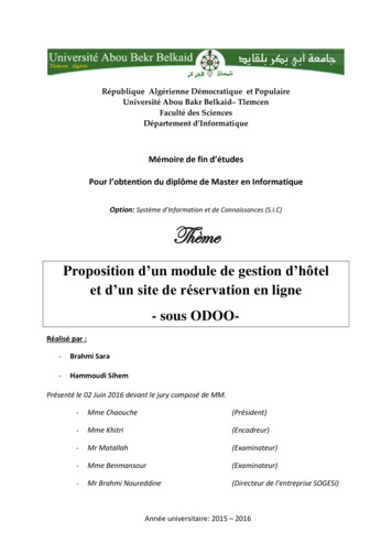
ContentsPrint(1)(2)where, va, b and c : motor terminal voltages, Via, b and c : motor phase currents, Aea, b and c : back-EMF voltages, VR : motor winding resistance, ΩL : motor winding inductance, Hωm : motor angular speed, rad/sTe : motor torque, N mThe motor torque is generated by the sum of products ofback-EMF and motor current as shown in Figure 3 andequation (2). However, it is inversely proportional to themotor speed, yielding high torque at low speed and lowtorque at high speed.closed-loop operation. But there is significant torqueripple generated from the non-linearities in thecommutation scheme, because only two motor windingscarry current at any given time. The non-linearitiesgenerate noise and vibration. The current controller mustbe slow enough so that it does not react to the transientsfrom the current transfer from phase to phase; thus, itlimits the performance. In order to generate high torquewith trapezoidal commutation, the 180o commutationmethod should be chosen, but the 120o commutationprovides minimum torque ripple.The six operational modes are shown in Figure 6 with1200 commutation strategy with Hall-effect positionfeedback sensor. Each section has a 600 interval in orderto conduct two motor phases at the same time. Theswitching sequence is determined to conduct two motorphases consecutively as the motor spins [2].II. COMMUTATION STRATEGIESIn order to drive the BLDC motor, an electroniccommutation circuit is required. This paper deals with theposition sensor-based commutation only. The widely usedcommutation methods for the BLDC motor aretrapezoidal (or six-step), sinusoidal, and field orientedcontrol (FOC) (or vector control). Each commutationmethod can be implemented in different ways, dependingon control algorithms and hardware implementation toprovide their own distinct advantages.Fig. 4 Three-phase Hall sensor timing chart with 120 angle separationA. Trapezoidal CommutationThe Hall-effect sensor is the most cost effective way ofrotor position sensing. The timing diagram of threetypical Hall sensors with 120o angle separation is shownin Figure 4. The experimental waveforms of three Hallsignals in both clockwise (CW) and counterclockwise(CCW) directions of motor rotation are shown in Figure5. The direction of rotation is viewed at the motor shaft.The sequences of the Hall signals are Hall A-Hall B-HallC in CW and Hall B-Hall C-Hall A in CCW direction.The trapezoidal (six-step) commutation makes twoswitching power devices on each motor phase in apredetermined sequence. This method is very popularbecause of the simplicity of its control algorithm. It uses asix-step sequence using three Hall-effect sensors to getrotor position information. It is very effective atcontrolling motor speed, but suffers from torque rippleduring commutation, especially at low speed. Therefore, itis popular for low-end applications requiring simple(a) CW direction(b) CCW directionFig. 5 Measured Hall signals in CW and CCW direction at 1500r/min(CH1: Hall A, CH2: Hall B, CH3: Hall C)(Vertical: 2V/div, Time: 5ms/div)
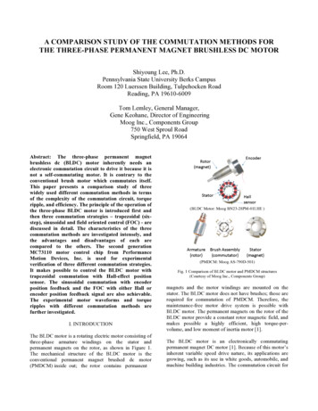
ContentsPrintoperated as an open- or closed-loop configuration using aspeed feedback sensor and is typically used in midrangeperformance applications requiring speed and torquecontrol.Figure 8 shows a simplified block diagram of a sinusoidalcommutation scheme with the MC7310 motor control IC[3]. The sinusoidal lookup table provides two sinusoidalmotor phase current command signals. In addition to theencoder, the Hall-effect sensors are required forinitializing sinusoidal commutation. The sinusoidalcommutation modulates the three-phase motor currentswhich produces smooth and precise motor control. It alsoeliminates the torque ripple and non-linearities in motorcurrent, which occur inherently with the six-stepcommutation.Fig. 8 Simplified block diagram of a sinusoidal drive schemeFig. 6 Trapezoidal (six-step) commutation with Hall sensors(a) Back-EMF VAB(a) Mode II (Q1, Q5 ON)(b) Back-EMF VBC(b) Mode III (Q1, Q6 ON)Fig. 7 Equivalent circuit examples of two operational modesB. Sinusoidal CommutationThe sinusoidal drive scheme replaces the flat peak of thetrapezoid with a sinusoidal waveform that matches moreclosely the back-EMF. It is necessary to overlap thecommutation of phases, selectively firing more than onepair of power switching devices at a time. It can be(c) Back-EMF VCAFig. 9 Measured Hall signals and sinusoidal back-EMF waveforms.(CH1: Hall A, CH2: Hall B, CH3: Hall C, CH4: Back-EMF)Vertical: 2V/div(CH1,2,3) 2.5V/div(CH4), Time: 5ms/div
ContentsPrintThe sinusoidal commutation requires high resolutionposition feedback devices, such as optical encoder orresolver. This makes the sinusoidal commutation moreexpensive than the six-step commutation. But it providesreduced torque ripple and allows precise control.Figure 9 shows the measured Hall signals and the backEMF waveforms of the PMSM (Moog BN23-28PM01LHE). The back-EMF VAB is in phase with the inverseof the Hall B waveform. In the next image, back-EM FVBC is in phase with the inverse of Hall C. Finally, theback-EMF VCA is in phase with the inverse of Hall A.The proper commutation logic with the rotor positioninformation provides correct switching sequences of thepower switching devices.Fig. 10 Simplified block diagram of a FOCC. Field Oriented ControlThe FOC is suitable for the high-end application due to itscomplex design and higher processing requirements. Itcommutates the motor by calculating voltage and currentvectors based on motor current feedback. It maintainshigh efficiency over a wide operating range and allowsfor precise dynamic control of speed and torque.The FOC controls the stator currents represented by aspace vector [5, 6]. It transforms three-phase statorcurrents into a flux generating part and a torquegenerating part and controls both quantities separately.The arrangement of the FOC controller resembles aseparately excited DC motor. The simplified blockdiagram of a FOC is shown in Figure 10 [3].The various reference frame transformations in FOC areshown in Figure 11 [6]. The Clarke transformationconverts the three-phase sinusoidal system (A, B, C) intoa two-phase time variant system (α, β). A two-coordinatetime invariant system (d, q) is obtained by the Parktransformation. In this system, the motor flux generatingpart is d (direct) and a torque generating part is q(quadrature).The space vector modulation (SVM) provides moreefficient use of the bus voltage than the conventionalsinusoidal pulse width modulation (SPWM) technique.The maximum output voltage based on the SVM is 1.15times bigger than the conventional SPWM. The SVMconsiders the power circuit as one device which affects allsix power switching devices because it controls thevoltage vector [6].The characteristics of three different commutationmethods for the BLDC motor and PMSM are summarizedin Table 2 [7, 8].Fig. 11 Various coordinate transformations in FOC systemTable 2. Characteristics of commutation methodsfor the BLDC motor and PMSMCommutationMethodsSpeedControlTorque urrentSensor,EncoderMediumHighIII. COMPARISON OF GENERATED TORQUERIPPLES WITH SIMULATION ANDEXPERIMENTAL VERIFICATIONA. Verification with SimulationIn order to verify the generated torque ripples withvarious combinations of two motor types and threedifferent commutation strategies, simulation results withMATLAB/Simulink software is shown in Figure 12.The simulation results verify that mismatch of the backEMF waveform and commutation method produces ripplerich torque. Therefore, the BLDC motor and trapezoidal(six-step) commutation and the PMSM and sinusoidalcommutation are the most desirable combination toproduce minimum torque ripple.B. Experimental VerificationThe experimental verification was performed with theMC73110 Developer’s Kit from Performance MotionDevices, Inc.The MC73110 motor control IC has developed into anadvanced single-chip, single-axis device that can be used
ContentsPrintwith MC73110 IC V2.2G and Pro-Motor V2.51. Thereare four possible commutation methods as listed below:- Hall-effect sensor based trapezoidal commutation- Encoder-based sinusoidal commutation- Hall-effect sensor based FOC- Encoder-based FOC(a) Trapezoidal commutation with BLDC(b) Trapezoidal commutation with PMSMA quadrature encoder and three Hall-effect sensorstogether are required to implement the sinusoidal drive.The FOC drive can be realized by either a quadratureencoder or three Hall-effect sensors.The experimental setup to verify three differentcommutation methods is shown in Figure 14. The testedmotor was PMSM (Moog BN23-28PM-01LHE) and themotor terminal voltage and motor current waveforms ofboth trapezoidal (six-step) and FOC drives are shown inFigures 15 and 16.(c) Sinusoidal Commutation with PMSMFig. 12 Simulation results of different combination ofcommutation strategies and motor type(Top) Torque (Center) Motor current (Bottom) Back-EMFto implement an intelligent three-phase BLDC motorcontroller based on FPGA and ASIC technologies [3]. Itis packaged in a 64-pin thin quad flat pack (TQFP)measuring 12 mm by 12 mm and operates on 3.3V. It canbe operated in internal velocity profile mode, velocitymode with an external analog, digital velocity commandsignal, or torque mode with an external torque commandsignal. It also can be operated as a standalone controllerusing pre-programmed parameters stored onto chip flashmemory or through the RS-232 serial port using the ProMotor GUI setup software. The simplified functionalblock diagram of the MC73110 is shown in Figure 13.The various functions useful for the development of theBLDC motor drive are embedded in the MC73110 IC.These functions include, for example: the three-phasePWM generation for three-phase full-bridge power circuitand three-signal PWM for single switch per phase powercircuit configuration, Hall- or quadrature encoder-basedcommutation, digital current and velocity loops, profilegeneration, emergency stop, analog velocity command,and RS-232 serial communication port. In addition to theconventional six-step with Hall-effect sensors andsinusoidal commutation with encoder, FOC is possibleFig. 13 Simplified functional block diagram ofMC73110 motor control ICPMSMController&AmplifierFig. 14 Experimental setup for commutation strategies
ContentsPrintThe sinusoidal commutation provides smooth operation atlow speeds, but it is inefficient in high speed range. TheFOC gives the best of both trapezoidal and sinusoidalcommutations – smooth operation at low speed andefficient running at high speed. The torque ripple can besignificantly reduced by matching the motor type with thecommutation strategy. The adequate combinations forproducing minimum toque ripple are the BLDC motorwith the six-step commutation and the PMSM with thesinusoidal commutation. The FOC can apply to both typesof motor to get the best drive performances, but it mayrequire extra code development and hardwarecomponents. The motor current waveforms are sinusoidalwith both the sinusoidal and the FOC commutation cases.Fig. 15 Relationship between motor line-to-line voltage (Top: 25V/div)and line current (Bottom: 0.5A/div) with six-step commutationFig. 16 Relationship between motor line-to-line voltage (Top: 25V/div)and line current (Bottom: 0.5A/div) with FOC commutationThe Hall-effect sensor-based trapezoidal drive and FOCdrive provide a similar six-step current waveform asshown in Figure 15. In other hand, encoder-basedsinusoidal drive and FOC drive show sinusoidal motorcurrent waveform as shown in Figure 16. The line-to-linemotor terminal voltages are look similar with bothcommutation methods. The fast Fourier transform (FFT)of voltage waveforms may reveal the difference betweentwo.IV. CONCLUSIONSThree different commutation strategies are compared, andtheir characteristics are investigated in this paper. Thetrapezoidal commutation generates torque ripples at lowspeeds and is relatively efficient in the high speed range.REFERENCES[1]R. Krishnan, “Electric Motor Drives Modeling,Analysis and Control,” 2001 Prentice Hall.[2]Shiyoung Lee, “Application of a SoftwareConfigurable Digital Servo Amplifier to anElectric Machine Control Course,” InternationalJournal of Modern Engineering, Vol. 9, No. 2,Spring/Summer 2009, pp. 49-57.[3]Performance Motion Devices, Inc., “MC73110Advanced 3-Phase Motor Control IC ProductManual,” Revision 2.2, March 2007.[4]Peter Vas, “Vector Control of AC Machines,”1990 Oxford University Press.[5]Freescale Semiconductor, “PMSM VectorControl with Single-Shunt Current-SensingUsing MC56F8013/23 – Design ReferenceManual,” DRM102, April 2008.[6]Texas Instruments, “Field Oriented Control of 3Phase AC-Motors,” BPRA073, February //america.renesas.com (Renesas Technology– Motor Control)[8]Copley Controls, “What is ‘Field OrientedControl’ and what good is it?” Copley ControlsCorp.
The BLDC motor is a rotating electric motor consisting of three-phase armature windings on the stator and permanent magnets pon the rotor, as shown in Figure 1. Th e mechanical structure of the BLDC motor is the conventional permanent magnet brushed dc motor (PMDCM)