Transcription
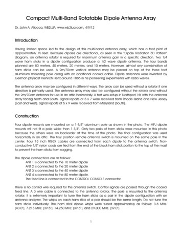
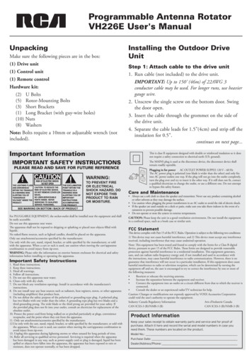
Programmable Antenna RotatorVH226E User's ManualUnpackingMake sure the following pieces are in the box:(1) Drive unit(1) Control unit(1) Remote controlHardware kit:(2) U Bolts(5) Rotor-Mounting Bolts(3) Short Brackets(1) Long Bracket (with guy-wire holes)(10) Nuts(8) WashersNote: Bolts require a 10mm or adjustable wrench (notincluded).Important InformationPLEASE READ AND SAVE FOR FUTURE REFERENCEWARNING:TO PREVENT FIREOR ELECTRICALSHOCK HAZARD, DONOT EXPOSE THISPRODUCT TO RAINOR MOISTURE.For PLUGGABLE EQUIPMENT, the socket-outlet shall be installed near the equipment and shallbe easily accessible.Do not use this apparatus near water.The apparatus shall not be exposed to dripping or splashing or placed near objects filled withliquids.No naked flame sources, such as lighted candles, should be placed on the apparatus.Only use attachments/accessories specified by the manufacturer.Use only with the cart, stand, tripod, bracket, or table specified by the manufacturer, or soldwith the apparatus. When a cart or rack is used, use caution when moving the cart/apparatuscombination to avoid injury from tip-over.WARNING: Please refer the information on exterior bottom enclosure for electrical and safetyinformation before installing or operating the apparatus.1.2.3.4.5.6.7.Step 1: Attach cable to the drive unit1. Run cable (not included) to the drive unit.IMPORTANT: Up to 150’ (46m) of 22AWG 3conductor cable may be used. For longer runs, use heaviergauge wire.2. Unscrew the single screw on the bottom door. Swingthe door open.3. Insert the cable through the grommet on the side ofthe drive unit.4. Separate the cable leads for 1.5”(4cm) and strip off theinsulation for 0.5”.continues on next page.This is class II equipment designed with double or reinforced insulation so it doesnot require a safety connection to electrical earth (US: ground).IMPORTANT SAFETY INSTRUCTIONSImportant Safety InstructionsInstalling the Outdoor DriveUnitRead these instructions.Keep these instructions.Heed all warnings.Follow all instructions.Do not use this apparatus near water.Clean only with dry cloth.Do not block any ventilation openings. Install in accordance with the manufacturer’sinstructions.8. Do not install near any heat sources such as radiators, heat registers, stoves, or other apparatus(including amplifiers) that produce heat.9. Do not defeat the safety purpose of the polarized or grounding-type plug. A polarized plughas two blades with one wider than the other. A grounding type plug has two blades and athird grounding prong. The wide blade or the third prong are provided for your safety. Ifthe provided plug does not fit into your outlet, consult an electrician for replacement of theobsolete outlet.10. Protect the power cord from being walked on or pinched particularly at plugs, conveniencereceptacles, and the point where they exit from the apparatus.11. Only use attachments/accessories specified by the manufacturer.12.Use only with the cart, stand, tripod, bracket, or table specified by the manufacturer, or sold withthe apparatus. When a cart is used, use caution when moving the cart/apparatus combination toavoid injury from tip-over.13. Unplug this apparatus during lightning storms or when unused for long periods of time.14. Refer all servicing to qualified service personnel. Servicing is required when the apparatushas been damaged in any way, such as power-supply cord or plug is damaged, liquid has beenspilled or objects have fallen into the apparatus, the apparatus has been exposed to rain ormoisture, does not operate normally, or has been dropped.The MAINS plug is used as the disconnect device, the disconnect device shallremain readily operable.Plugging in for power AC OUTLET POWER SUPPLY: 120 V 60 HzThe AC power plug is polarized (one blade is wider than the other) and only fitsinto AC power outlets one way. If the plug will not go into the outlet completely,turn the plug over and try to insert it the other way. If it still does not fit, contacta qualified electrician to change the outlet, or use a different one. Do not attemptto bypass this safety feature.Care and Maintenance Always use a soft cloth to clean the speaker and transmitter. Never use any product containing alcoholor other solvents as they may damage the surface. Use caution when plugging the power transformers in an AC outlet to avoid the risk of electric shock. If the speaker are used outside on a deck or patio, make sure you take them indoors in the event of arainstorm to prevent possible damage. Do not operate or store the system in extreme temperatures.CAUTION: Please keep the unit in a good ventilation environment. Do not install the equipmentin a confined space, such as a book case or similar unit.FCC StatementThis device complies with Part 15 of the FCC Rules. Operation is subject to the following two conditions:1) This device may not cause harmful interference, and 2) This device must accept any interferencereceived, including interference that may cause undesired operation.Note: This equipment has been tested and found to comply with the limits for a Class B digitaldevice, pursuant to part 15 of the FCC Rules. These limits are designed to provide reasonableprotection against harmful interference in a residential installation. This equipment generates,uses, and can radiate radio frequency energy and, if not installed and used in accordance withthe instructions, may cause harmful interference to radio communication. However, there is noguarantee that interference will not occur in a particular installation. If this equipment does causeharmful interference to radio or television reception, which can be determined by turning theequipment off and on, the user is encouraged to try to correct the interference by one or more ofthe following measures: Reorient or relocate the receiving antenna. Increase the separation between the equipment and receiver. Connect the equipment into an outlet on a circuit different from that to which the receiver isconnected. Consult the dealer or an experienced radio/TV technician for help.Caution: Changes or modifications not expressly approved by VOXX Accessories Corporationcould void the user’s authority to operate the equipment.Industry Canada Regulatory InformationAvis d’Industrie CanadaCAN ICES-3 (B)/NMB-3 (B)CAN ICES-3 (B)/NMB-3 (B)Product InformationKeep your sales receipt to obtain warranty parts and service and for proof ofpurchase. Attach it here and record the serial and model numbers in case youneed them. These numbers are located on the product.Model No.:Purchase Date:Dealer/Address/Phone:
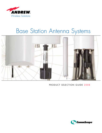
4. Position the brackets and nuts/washers so that theyleave just enough room for the support mast to gothrough.Bottom of the drive unitGrommetBottom door(3)(2)(1)Behind the doorSide of the drive unitTerminals:Silver (or wide) wire (red) to pin (1)Second wire (black) to pin (2)Third wire (green) to pin (3)WasherNutBoltIMPORTANT: To avoid moisture collecting in the cablemake sure the cable jacket passes thru the grommet.5. Find the silver- or wide-jacketed lead and connectit to pin (1). Connect the adjacent lead to pin (2).Connect the third lead to pin (3). If 4-wire cable isused, connect both wire 3 and 4 to pin (3).IMPORTANT: Make sure there are no loose strandswhich can short between terminals.6. Doublecheck the wiring order. Close the door andscrew it back into place.Short BracketLong Bracket5. Lower the drive unit onto the support mast until itstops on the mast nose of the drive housing. Tightenthe nuts. Moderate tightening with a 10mm oradjustable wrench will cause the teeth to grip the mastsecurely.Step 2: Mount the drive unitSide of the drive unitIf you’re not mounting the unit inside a tower, you’ll needto mount it to a separate mast (not included). This kitMast nosecomes with the necessary hardware for mounting.Support mastCAUTION: Select a mounting location where theantenna cannot come in contact with power lines while itis being installed, and where the installation will not fallacross power lines if a guy wire should fail.1. Screw four nuts onto four rotor-mounting bolts.Screw each nut all the way to the head of each bolt.Then put one washer on each of the bolts, next to thenut.2. Place a short bracket over two of the bolts, with theIMPORTANT: Do not overtighten to the point thatflat section of the bracket snug against the washerlessyou deform the mast, since this will reduce its strength.nuts. Place the long bracket over the other two boltsThe drive unit is designed for 1.25” diameters but willthe same way.accommodate up to 2” diameter support masts.3. Screw the short bracket/bolt assembly into the top6. (Optional) Attach guy wires (not included) to thetwo holes on the side of the drive unit base. Screw theholes in the bottom bracket.long bracket/bolt assembly into the bottom two holes.Screw each bolt as far as it will go into the drive unit.2
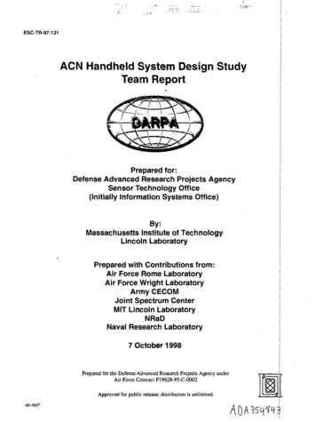
Step 3: Install the antenna/cable1. Insert the 2 U-bolts through the back of the rotorsection of the drive unit.2. Place the remaining 2 brackets over the ends of theU-bolts.3. Put a washer and nut on the very end of the U-boltsto keep the brackets in place.4. Position the brackets and nuts/washers so that theyleave just enough room for the antenna mast to gothrough.Note: Use no more than 3 feet of antenna mast betweenthe rotor and the antenna itself.5. Lower the antenna mast between the brackets and therotor. Tighten the nuts. Moderate tightening with a10mm or adjustable wrench will cause the teeth togrip the mast securely.WasherNutU-Bolt7. Attach the lead-in cable to the support mastwith cable tie/stand-off insulators (not included)approximately every four feet.8. Tape the rotator control cable directly to the supportmast.Installing and Programmingthe Indoor Control UnitStep 1: Set up to the control unit1. Determine the length of cable needed to run betweenthe outdoor and indoor units. Cut the cable to thatlength.2. Strip about 1/2” of the jacket off the end of each wire.1/2"3 wire (green) #3 to #32 wire (black) #2 to #21 wire (red) #1 to #1Side of the drive unitBracket3. Insert each bare wire into the connector plate on thecontrol unit’s back panel as shown below.1AntennaCable tie/stand-offLoop to allow fullturn of antennaDrive unitControl cableTape to mastSupport mast34. Release jacket to secure on connector.IMPORTANT: The unit must be wired correctly.Damage can result from improper wiring.5. Plug power cord of the control unit into an AC outlet.6. Turn on the unit by putting the switch on the rightside of the control unit in the on position.The MEMORY display on the front panel reads 0,and the DEGREE X 10 display reads 00.6. After connecting the antenna lead-in cable to theantenna, fasten it to the antenna mast using cable tie/stand-off insulators or electrical tape (not included) asshown. Provide a generous loop at the drive unit.Antenna mast(3 foot max)2Cable tie/stand-offAntenna lead-in cable3
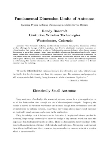
Step 2: Initialize the control unit1. Make sure the control unit is on (if it isn’t, putthe switch on the right side of the unit in the onposition).2. Press the INITIAL button on the control unit’s frontpanel. The control unit and rotator are initializingto prepare for initial setup. The MEMORY andDEGREE X10 indicators blink during this process,which takes about a minute and a half.Step 3: Program the control unit1. Tune your TV to the station that you want to receive.2. While watching your TV screen, press the and buttons on the control unit’s front panel to move theantenna clockwise ( ) and counter-clockwise ( ) untilyou find the position that gives you the best receptionfor this channel.3. When you’ve found the best antenna position for thischannel, press the MEMORY button on the controlunit’s front panel. The MEMORY and DEGREE X10indicators blink.When the MEMORY and DEGREE X10 indicatorsstop blinking, the control unit and rotator are readyfor setup.4. Press one of the letter buttons on the control unit’sfront panel to store the antenna position for thisstation to that button. The DEGREE X10 indicatorshows the degree of the antenna’s position.Note: Using a letter button that already has a positionstored to it in this step erases the old position stored andstores the new one.5. Use the Memory Location Chart that comes withthis product for recording the channel and antennaposition corresponding to each letter button. Writedown this information on this chart.6. Repeat steps 3-7 for the next TV station. Choose adifferent letter button to store its location.You can store up to 12 antenna positions so thatyou can easily find the best reception for each TVstation.3. Check to make sure the control and drive units areproperly calibrated by looking at the position of thedrive unit and antenna at different DEGREE X10readings. Use the and buttons on the control unitto go to the following DEGREE X 10 readings, thencheck the drive unit/antenna position.DEGREE X10reads.Drive unit/antennaposition0009182736Starting position90º clockwise from start180º from start270º clockwise from startStarting positionIf the DEGREE X10 reading and the drive unit/antenna position don’t match, go to the Recalibratingthe Rotator section on the next page.NOTE: A strong storm or power failure may cause therotator to change position. Use the INITIAL button tore-synchronize the system. If this reset procedure doesn’t getthe desired results, the antenna of driver motor may bemisaligned on the antenna mast. You can either go to theantenna and re-orient it or program the control unit tocorrespond to the new antenna orientation.4
Re-Calibrating the RotatorStep 4: Install batteries in the remoteThis antenna rotator comes from the factory calibratedand ready to set up. However, if you notice that thecontrol unit’s display and the drive unit’s position donot match (for example, if the display reads 30 but theantenna has done a complete 360-degree rotation), youcan recalibrate the rotator to make them match again.1. Press the INITIAL button to return the drive unit toits starting position—the line on the rotator section ofthe drive unit should line up with the line on the baseonce this is finished.2. Press the INITIAL button a second time tocompletely reset the control and drive units.3. Press and hold the INITIAL and buttons on thecontrol unit’s front panel—make sure you press theINITIAL button slightly before the button. Keepholding these buttons down as the display startscounting up in seconds.If the display starts counting down from 36, thecontrol unit is in initialization mode, not calibrationmode. Let the rotator finish initialization, then trystep 2 again, this time pressing the button morequickly after the INITIAL button.4. Watch the antenna and drive unit—when it completesa full 360-degree turn, release the INITIAL and buttons on the control unit. This typically takes about57 seconds.The DEGREE X10 indicator displays the rotatorcycle time. The control unit uses this information tokeep the antenna positions and program locationssynchronized.1. Press and push thebattery compartmentcover to remove it.2. Insert the batteries,matching the batteriesto the ( ) and (–)marks inside thebattery compartment.3. Push the battery coverback into place.Battery Precautions: Do not mix old and new batteries. Do not mix alkaline, standard (carbon-zinc) orrechargeable (nickel cadmium) batteries. Always remove old, weak or worn-out batteries promptlyand recycle or dispose of them in accordance with Localand National Regulations.Using the ProgrammableAntenna RotatorTo go to a programmed antenna position: Press theletter button for that position on the remote or on thecontrol unit’s front panel.The drive unit turns the antenna to that position, andthe control unit displays the position of the antenna indegrees.To stop the rotator while it’s going to a programmedposition: Turn the control unit off, then turn it back on.Press the INITIAL button to resynchronize the unit.To fine-tune the antenna position (or positionmanually): Press the or buttons on the remotecontrol or control unit’s front panel to move the antennaclockwise ( ) or counter-clockwise ( ).Resetting the Memory ButtonsResetting the control unit’s memory buttons erases allprogrammed antenna positions.1. Turn off the control unit.2. Press and hold the D button on the control unit’sfront panel.3. While holding the D button, turn the control unitback on. The CCW and CW indicators light up.4. Release the D button and turn the unit back off.5. Turn the unit back on a second time. The unit willperform the initialization procedure.The MEMORY on the front panel reads 0, and theDEGREE X10 display reads 00. The unit is resettingits memory.5
12 Month Limited WarrantyVoxx Accessories Corporation (the “Company”) warrants to the original retailpurchaser of this product that should this product or any part thereof, undernormal use and conditions, be proven defective in material or workmanshipwithin 12 months from the date of original purchase, such defect(s) will berepaired or replaced with new or reconditioned product (at the Company’soption) without charge for parts and repair labor.To obtain repair or replacement within the terms of the warranty, the productis to be delivered with proof of warranty coverage (e.g. dated bill of sale),specification of defect(s), transportation prepaid, to an approved warrantystation. For the location of the nearest warranty station to you, call toll-free toour control office: 1-800-645-4994.This Warranty is not transferable and does not cover product purchased,serviced or used outside the United States or Canada. The Warranty does notextend to the elimination of externally generated static or noise. This Warrantydoes not apply to costs incurred for installation, removal or reinstallation ofthe product, or, if in the Company’s opinion, the product has been damagedthrough acts of nature, alteration, improper installation, mishandling, misuse,neglect, or accident. This Warranty does not cover damage caused by an ACadapter not provided with the product.THE EXTENT OF THE COMPANY’S LIABILITY UNDER THISWARRANTY IS LIMITED TO THE REPAIR OR REPLACEMENTPROVIDED ABOVE AND, IN NO EVENT, SHALL THE COMPANY’SLIABILITY EXCEED THE PURCHASE PRICE PAID BY PURCHASERFOR THE PRODUCT.This Warranty is in lieu of all other express warranties or liabilities. ANYIMPLIED WARRANTIES, INCLUDING ANY IMPLIED WARRANTYOF MERCHANTABILITY OR FITNESS FOR A PARTICULARPURPOSE, SHALL BE LIMITED TO DURATION OF THISWARRANTY. ANY ACTION FOR BREACH OF ANY WARRANTYHEREUNDER, INCLUDING ANY IMPLIED WARRANTY, MUST BEBROUGHT WITHIN A PERIOD OF 24 MONTHS FROM THE DATEOF ORIGINAL PURCHASE. IN NO CASE SHALL THE COMPANY BELIABLE FOR ANY CONSEQUENTIAL OR INCIDENTAL DAMAGESWHATSOEVER. No person or representative is authorized to assume for theCompany any liability other than expressed herein in connection with the saleof this product.Some states/provinces do not allow limitations on how long an impliedwarranty lasts or the exclusion or limitation of incidental or consequentialdamage so the above limitations or exclusions may not apply to you. ThisWarranty gives you specific legal rights and you may also have other rightswhich vary from state/province to state/province. 2019 VOXX Accessories Corporation3502 Woodview Trace, Suite 200 Indianapolis, IN 46268Trademark(s) RegisteredMade in ChinaVH226E US IB 00
Manual del Usuario del Rotadorde Antena Programable VH226EDesempaqueAsegúrese que la caja contenga las siguientes piezas:(1) Unidad de mando(1) Unidad de control(1) Control remotoJuego de herrajes:(2) Pernos en U(5) Pernos de montaje del rotor(3) Soportes cortos(1) Soporte largo (con orificios para cables de sujeción)(10) Tuercas(8) ArandelasAviso: Los pernos requieren una llave ajustable o de 10mm (no incluidas).Instalación de la unidad demando para exterioresPaso 1: Conecte el cable en la unidad demando.1. Tienda el cable (no incluido) hacia la unidad de mando.IMPORTANTE: Puede utilizarse hasta 150 pies (46m) de cable de 3 conductores 22AWG. Para mayoresdistancias de cable, utilice un cable de mayor calibre.2. Desenrosque el tornillo de la puerta inferior. Abra la puerta.3. Inserte el cable a través del ojal que se encuentra en unlado de la unidad de mando.4. Separe los conductores del cable hasta una longitud de1.5 pulgadas (4 cm) y desforre el aislamiento hasta unalongitud de 0.5 pulgadas (1.27 cm).continúa en la siguiente página Información ImportanteEste es un equipo clase II diseñado con doble aislamiento o refuerzo de maneraque no requiera una conexión de seguridad a tierra eléctrica (EE.UU.: tierra).IMPORTANTE INSTRUCCIONES DE SEGURIDADEl enchufe de la red eléctrica (MAINS) se utiliza como el dispositivo dedesconexión, éste deberá estar siempre listo para funcionar.FAVOR DE GUARDAR ESTO PARA UNA REFERENCIA FUTURAADVERTENCIA:PARA EVITARPELIGRO DECHOQUE ELÉCTRICOO INCENDIO, NOEXPONGA ESTE PRODUCTO ALA LLUVIA O LAHUMEDAD.Para EQUIPO ENCHUFABLE, el conector-tomacorriente debe instalarse cerca del equipo y ser defácil acceso.No use este aparato cerca del agua.El aparato no deberá exponerse a goteos o salpicadura,ni colocarse cerca de objetos que contengan líquidos.Ninguna fuente de fl ama abierta, tal como velas encendidas, deberá colocarse sobre el aparato.Use solamente accesorios/aditamentos especificados por el fabricante.Use solamente con el carro, soporte, trípode, consola, o mesa especificados por el fabricante, ovendidos con el aparato. Cuando se utiliza un carro, tenga precaución al mover la combinación decarro/aparato para evitar lesión ocasionada por volcadura.ADVERTENCIA: Por favor, consulte la información en el cierre inferior exterior sobre seguridadeléctrica y seguridad antes de instalar o manejar el aparato.Importantes Instrucciones de Seguridad1. Lea estas instrucciones.2. Guarde estas instrucciones.3. Preste atención a todas las advertencias.4. Acate todas las instrucciones.5. No use este aparato cerca del agua.6. Limpie sólo con un trapo seco.7. No obstruya ningún orificio de ventilación. Instale en conformidad con las instrucciones del fabricante.8. No instale cerca de fuentes térmicas, como radiadores, reguladores de calefacción, cocinas y otrosaparatos que generen calor (incluidos los amplificadores).9. No anule el propósito de seguridad que tiene el enchufe polarizado o puesto a tierra. Un enchufepolarizado tiene dos paletas, una más ancha que la otra. Un enchufe puesto a tierra tiene dospaletas y una espiga de conexión a tierra. La paleta más ancha, o la tercera espiga se incluyen porsu seguridad. Si el enchufe provisto no encaja en su tomacorriente, solicítele a un electricista quereemplace ese tomacorriente obsoleto.10. Proteja el cable de alimentación de modo que no resulte pisado ni aprisionado, especialmente enel enchufe, la caja de contacto y el punto por donde sale del aparato.11. Use sólo accesorios especificados por el fabricante.12.Use sólo con el carrito, base, trípode, soporte o mesa que especifica el fabricante o que se vendecon el aparato. Si usa un carrito, tenga cuidado al moverlo junto con el aparato para evitar que sevoltee y haga daño.13. Desenchufe este aparato en caso de tormentas o de lapsos prolongados de inactividad.14. Solicite al personal técnico calificado todo tipo de mantenimiento del producto. Es necesariodarle mantenimiento al aparato si ha sido averiado de alguna forma, por ejemplo, si se ha dañadoel cable de alimentación o el enchufe, si se le ha derramado algún líquido encima, si han caídoobjetos en su interior, si ha sido expuesto a la lluvia o la humedad, si no funciona correctamenteo si se ha dejado caer.Conexión a la red FUENTE DE ALIMENTACIÓN CA: 120 V 60 HzLa toma de alimentación CA está polarizada (una de las clavijas es más ancha que laotra) y solo encaja en la toma de alimentación CA en un sentido. Si la clavija no encajacompletamente en el enchufe, dé la vuelta a la clavija e insértela de la otra forma. Si siguesin encajar, póngase en contacto con un electricista calificado para que cambia el enchufeo utilice uno distinto. No intente puentear este dispositivo de seguridad.Cuidado y Mantenimiento Siempre utilice un paño suave para limpiar el altavoz y el transmisor. Nunca utilice productosque contengan alcohol u otros solventes ya que estos podrían ocasionar daños a la superficie. Tenga precaución al enchufar los transformadores de potencia en un tomacorriente de CA paraevitar el riesgo de choque eléctrico. Si se utiliza el altavoz en una terraza o patio, asegúrese de almacenarlo en el interior en caso detormentas para evitar posibles daños. No utilice ni almacene el sistema en condiciones de temperaturas extremas.ATENCIÓN: Por favor mantenga la unidad en un entorno con buena ventilación. No instale el equipo enun espacio cerrado, tal como en una estantería de libros o una unidad similar.Declaración de la Comisión Federal de Comunicacionesde los Estados UnidosEste dispositivo cumple con la Parte 15 de las Reglas de la FCC. Su funcionamiento está sujeto alas siguientes dos condiciones:1) Este dispositivo no debe causar interferencia y 2) Este dispositivo debe aceptar toda interferenciarecibida, incluida aquélla que puede causar un funcionamiento no deseado.Aviso: Este equipo ha sido probado, y se consideró que cumple con los límites de los aparatosdigitales de Clase B, de acuerdo con las especificaciones de la Parte 15 de las Reglas de la FCC. Elobjetivo de estos límites es ofrecer una protección razonable contra interferencias nocivas en unainstalación residencial. Este equipo genera, utiliza y puede radiar energía de radiofrecuencia y, si nose instala y utiliza de acuerdo con estas instrucciones, puede generar interferencia perjudicial paralas radiocomunicaciones. Sin embargo, no se garantiza que no se producirá interferencia en unainstalación en particular.Si su equipo causa interferencia perjudicial para la recepción de radio o televisión, que se puedeaveriguar apagando y encendiendo el equipo, intente corregirla mediante uno o varios de lossiguientes procedimientos: Vuelva a orientar o cambie de lugar la antena receptora. Aumente la separación entre el equipo y el receptor. Conecte este equipo a un tomacorriente en un circuito diferente al que esté conectado el receptor. Consulte al distribuidor o a un técnico experimentado de radio y televisión para solicitar asistencia.Atención: Los cambios o modificaciones no aprobados expresamente por VOXX AccessoriesCorporation podrían anular la autoridad del usuario conferida para utilizar este equipo.Información Regulatoria de la Industria CanadienseCAN ICES-3 (B)/NMB-3 (B)Información sobre el ProductoGuarde el recibo como prueba de su compra y preséntelo para obtener repuestoso solicitar servicio bajo garantía. Anéxelo aquí y anote los números de serie y demodelo para referencia en caso necesario. Estos números se encuentranen el producto.Número de modelo:Fecha de Compra:Distribuidor/Dirección/Teléfono:
Detrás de la puerta.4. Coloque los soportes y las tuercas/arandelas de formaque dejen espacio suficiente para que el mástil desoporte pueda atravesar.Parte inferior de la unidad de mandoPuerta inferior(3)(2)(1)OjalLado de la unidadde mandoTerminales:Conductor plateado (o ancho) (rojo) a la clavija (1)Segundo conductor (negro) a la clavija (2)Tercer conductor (verde) a la clavija (3)ArandelaTuercaIMPORTANTE: Para evitar la acumulación dehumedad en el cable, asegúrese que la cubierta del cablepase a través del ojal.PernoSoporte cortoSoporte largo5. Encuentre el conductor con cubierta plateada o anchay conéctelo a (1). Conecte el conductor adyacente a(2). Conecte el tercer conductor a (3). Si se utiliza uncable con 4 conductores, conecte los conductores 3 y4 a (3).5. Descienda la unidad de mando sobre el mástil deIMPORTANTE: Asegúrese que no haya hilos sueltos quesoporte hasta que tope en el saliente del mástil delpuedan ocasionar un cortocircuito entre las terminales.alojamiento de la unidad de mando. Apriete lastuercas. Un apriete moderado con una llave ajustable o6. Verifique nuevamente el orden del cableado. Cierre lade 10 mm causará que los dientes sujeten firmementepuerta y fíjela con el tornillo.el mástil.Paso 2: Monte la unidad de mando.Lado de la unidad de mandoSi no va a montar la unidad dentro de una torre, tendráSaliente del mástilque montarla en un mástil separado (no suministrado).Este juego incluye el herraje de montaje necesario.Mástil de soporteATENCIÓN: Seleccione una ubicación de montajedonde la antena no pueda entrar en contacto con líneas dealimentación eléctrica mientras se esté llevando a cabo lainstalación, y donde la instalación no caiga sobre líneas dealimentación eléctrica si fallara algún cable de sujeción.1. Enrosque cuatro tuercas en los cuatro pernos demontaje del rotor. Enrosque completamente cadatuerca hasta la cabeza de cada perno. Luego coloqueIMPORTANTE: No apriete demasiado hasta eluna arandela en cada uno de los pernos, al lado de lapunto que se deforme el mástil, ya que esto reducirá sutuerca.resistencia. La unidad de mando está diseñada para2. Coloque un soporte corto sobre dos de los pernos,diámetros de 1.25 pulgadas (3.2 cm), pero acomodarácon la sección plana del soporte bien ceñida contra lasmástiles de soporte de hasta 2 pulgadas (5.1 cm) detuercas sin arandela. Coloque el soporte largo sobre losdiámetro.otros dos pernos de la misma manera.6. (Opcional) Instale cuatro cables de sujeción (no3. Enrosque el conjunto de soporte corto y pernos enincluidos) en los orificios del soporte inferior.los dos orificios superiores ubicados en el lado de labase de la unidad de mando. Enrosque el conjunto desoporte largo y pernos en los dos orificios inferiores.Enrosque cada perno tanto como pueda en la unidadde mando.2
Paso 3: Instale la antena/cable1. Inserte los 2 pernos en U a través de la parte posteriorde la sección del rotor de la unidad de mando.2. Coloque los 2 soportes restantes sobre los extremo
2. Keep these instructions. 3. Heed all warnings. 4. Follow all instructions. 5. Do not use this apparatus near water. 6. Clean only with dry cloth. 7. Do not block any ventilation openings. Install in accordance with the manufacturer’s instructions. 8. Do not install near any heat source