Transcription
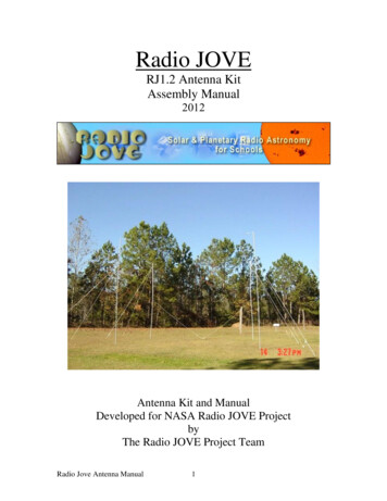
Radio JOVERJ1.2 Antenna KitAssembly Manual2012Antenna Kit and ManualDeveloped for NASA Radio JOVE ProjectbyThe Radio JOVE Project TeamRadio Jove Antenna Manual1
Table of ContentsPage31. Introduction1.1 Locating Jupiter and the Sun in the Sky31.2 Declination, Latitude, and Elevation Angle31.3 Declination and Elevation of the Sun31.4 Declination and Elevation of Jupiter452. Basic Antenna Theory2.1 Gain and Beaming Pattern52.2 Frequency and Wavelength563. Antennas for JOVE3.1 The Dipole Antenna63.2 Beaming Pattern of a Dipole above Ground93.3 Jove Dual Dipole Array103.4 The Principle of Antenna Beam Steering113.5 Radio Jupiter Pro (RJP)183.6 Some examples193.7 Antenna Configuration Summary19204. Antenna Pre-Assembly4.1 Site Requirements and Considerations204.2 Construction Time Estimate214.3 Antenna Components224.4 Radio JOVE Antenna Kit Parts List224.5 Items Supplied in Kit224.6 Additional Materials244.7 Tools24255. Preparing the Dipoles and Coaxial Cable5.1 Cutting the Wire and Coax255.2 Wrapping the Insulators25265.3 Preparing and Soldering the 1 Coax Lines5.4 Installing the Toroids and Connectors27296. Antenna Mast Assembly6.1 PVC Masts296.2 PVC Mast Assembly (Refer to Figures 6.1, 6.2, and 6.3) 296.3 Metal Masts336.4 Metal Mast Assembly (Refer to Figures 6.4 and 6.5)33367. Field Setup, Safety and Testing7.1 Weatherproofing the Antenna367.2 Field Setup367.3 Connecting Cables to the Antenna and Receiver407.4 Safety Precautions417.5 Testing the Antenna417.6 Troubleshooting your Antenna41Radio Jove Antenna Manual2
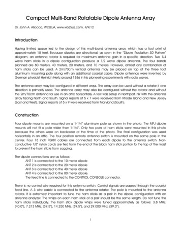
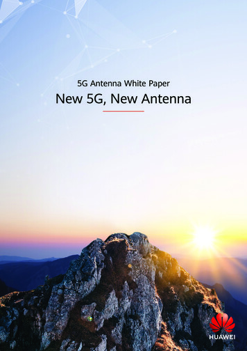
1. IntroductionWelcome to the third edition of the Jove antenna manual. This manual has been expandedover previous editions to include information for southern hemisphere observers as wellas those using the Jove radio telescope for solar observations. The antenna configurationyou use will be guided by the latitude of your observatory and the position of Jupiter andthe Sun in your sky.1.1 Locating Jupiter and the Sun in the Sky1.2 Declination, Latitude, and Elevation AngleWe use a system of latitude and longitude to describe locations on Earth, where latitude ismeasured north or south of the equator. Imagine that the earth’s equator is projectedoutward onto the celestial sphere (sphere of fixed stars). The angular position of acelestial object north or south of the celestial equator is known as declination. The anglemeasured upward from an observer’s horizon to a celestial object is called the elevationangle or altitude.1.3 Declination and Elevation of the SunDue to the tilt of the Earth’s axis, the Sun’s declination varies between 23.5 north (at theJune solstice) and 23.5 south (at the December solstice) of the celestial equator. Forobservers between 23.5 north and south latitude the Sun will be directly overhead atsome time during the year. Folks living at higher northern or southern latitudes never getto view the Sun directly overhead. The further you live from the equator, the lower theSun appears in the sky. The maximum elevation of the Sun (measured at local noon)varies throughout the year as seen in Figure 1.1 below.Figure 1.1. Shown is the maximum elevation angle of the Sun throughout the year for observers at differentlatitudes. Solid curves are for northern hemisphere observers (at 30 N, 40 N, and 50 N) and dashed curvesare for southern hemisphere observers (at 30 S, 40 S, and 50 S).Radio Jove Antenna Manual3
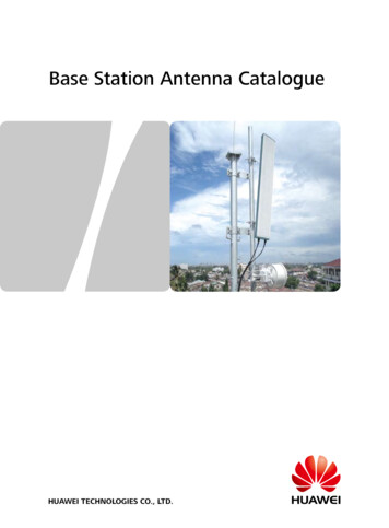
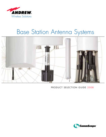
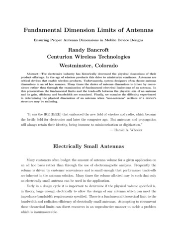
1.4 Declination and Elevation of JupiterJupiter’s declination also varies between 23.5 S and 23.5 N, with the complete cycletaking approximately 12 years (Figure 1.2). Northern declinations ( ) between 2011through 2016 favor northern hemisphere observers, while southern declinations (-) from2017 through 2023 favor the southern hemisphere.Figure 1.2. Jupiter’s declination varies between 23.5 N and 23.5 S.Jupiter can be observed from the northern hemisphere when it is at southern declinationsand from the southern hemisphere while at northern declinations. The Jove antenna beamcan be steered north, south, or overhead.The following two plots show Jupiter’s maximum elevation for northern hemisphere(Figure 1.3) and southern hemisphere (Figure 1.4) observing sites for the coming years.When Jupiter is at maximum northern declination in 2013 it will appear lowest forsouthern hemisphere observers. Six years later the situation is reversed with Jupiter’smaximum southern declination favoring southern hemisphere observers.Figure 1.3. In 2013 an observer at 30 N will see Jupiter’s elevation peak at 83 , while Jupiter will onlyreach 63 for an observer at 50 N. Each year is labeled at the January location.Radio Jove Antenna Manual4
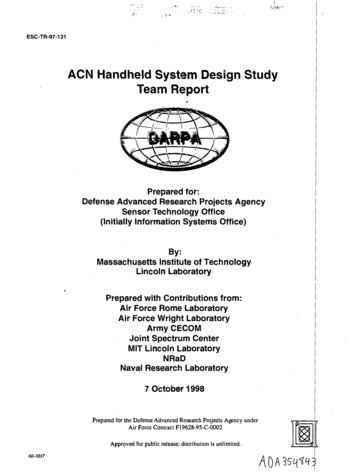
Figure 1.4. These curves show the maximum elevation angle for Jupiter for southern hemisphere observersat three different latitudes.When installing the Jove antenna it is important to understand where Jupiter (and theSun) will reside in the sky. You will configure the antenna differently depending on yourlatitude and the maximum elevation angle of Jupiter (or the Sun) during the plannedobserving campaign. For the case of Jupiter, the antenna configuration will only changeevery few years. To control where the antenna beam is steered you can (1) insert aphasing (delay) cable, and/or (2) change the height of the Jove antenna above ground.2. Basic Antenna TheoryA radio antenna intercepts energy from electromagnetic waves and converts that energyinto an electrical signal (current and voltage) at the antenna terminals. This weak radiofrequency signal is fed from the antenna through a transmission line (coaxial cable) to theradio receiver.2.1 Gain and Beaming PatternIf you held the small end of a cheerleader’s megaphone to your ear you would find that itamplifies sounds from certain directions while making it harder to hear sounds from otherdirections. Antennas have these same properties – the antenna has gain (it amplifiessignals) because it has a beaming pattern; it amplifies signals best coming from somedirections and attenuates (reduces) signals from other directions. The Jove antenna beamis tens of degrees wide so when it is aimed properly Jupiter takes several hours to passthrough the beam as the Earth rotates.2.2 Frequency and WavelengthA radio wave is an electromagnetic wave which travels through the vacuum of space atthe speed of light. Two important characteristics of the wave are its frequency and itswavelength. The frequency of the wave is the number of cycles that occur each second,and the wavelength is the distance that the wave travels during one cycle (Figure 2.1).Radio Jove Antenna Manual5
Figure 2.1. Wavelength is the distance between identicalpoints on a repeating waveformThe frequency (f), wavelength ( – Greek symbol lambda), and speed of light (c) arerelated by a simple equation:cfcfor[1]If the speed of light is given in meters per second (c 3x10⁸ m/s), and the frequency inhertz (Hz, which has units of “per second”), then the unit for wavelength is meters. TheJove antenna operates at a center frequency of 20.1 megahertz (MHz). The free-spacewavelength is therefore:3 108 m/s14.925 meters20.1 106 HzSince there are 3.28 feet per meter the wavelength at the Jove frequency is 48.955 feet.The formula relating free-space wavelength in feet (meters) to frequency (in MHz), andthe speed of light is:ft984f MHzorm300f MHz[2]3. Antennas for JOVE3.1 The Dipole AntennaOne of the simplest antennas is the dipole which can be made from two pieces of wireand three insulators (Figure 3.1). The length of a dipole antenna using infinitely thinwires is exactly half a wavelength ( /2). Much like an organ pipe is cut to a specificRadio Jove Antenna Manual6
length to make it resonant for a particular frequency of sound, our dipole antenna is cut toa length of half a wavelength to make it resonant at the frequency of 20.1 MHz. Since weare using real wire that is not infinitely thin we have to take into account some real worldeffects that shorten the actual antenna (these are called capacitive end effects).The formula for the length of a real world half-wavelength dipole antenna in feet(meters) is:2ft468f MHzor2m142.65f MHz[3]A dipole cut for 20.1 MHz has a length of 23.28 ft (23’ 3” or 7.09 m) as measured fromtip to tip of the wire.23.28 ft (7.09 m)Figure 3.1. The dipole antenna cut to resonance at the Jove frequency of 20.1 MHz.3.1.1 Dipole Antenna TerminalsAntenna terminals (also called the antenna feed point) are where you connect atransmission line to deliver signals from the antenna to the receiver. In the case of adipole, the feed point is located at either side of the central insulator – its where the twowires making up the transmission line connect to the two dipole wires.3.1.2 Transmission LineThe transmission line used in the Radio Jove project is called coaxial cable (Figure 3.2).It’s the same type of cable that you probably have connected to your TV set – about asbig around as a pencil with a central wire surrounded by a white insulating material(dielectric) inside of a braid covered with an outer layer of insulation.Radio Jove Antenna Manual7
CenterConductorBraid(Shield)Outer InsulationDielectricFig.3.2 Coaxial transmission line (coax), showing the layers of wire and insulation.Coaxial cable has two wires – the center conductor and the shield, which is either braidedcopper wire or a thin metallic sheath. Signals are conducted along the center conductorand on the inside of the braid. Several characteristics are important in describing coaxialcable. These include:Impedance – measured in ohms and determined by the internal dimensions and geometryof the cable. The coax used in the Jove antenna has an impedance of 75 ohms.Attenuation – a measure of how much signal is lost due to wire resistance and dielectriclosses in the transmission line. Less loss is better. Attenuation increases with frequencyand is typically measured in decibels (dB) per hundred feet of cable. A loss of 3 dBmeans half the power that enters the cable is lost before reaching the other end. For aRadio Jove installation, the maximum acceptable loss is 6 dB. The coax cable providedwith the Jove kit is manufactured by Belden Company (their type 8241) and is designatedas RG-59/U. At 20.1 MHz it has a loss of 1.5 dB per 100 ft, which means that when usingthis cable the recommended separation between the antenna and the receiver is less than200 feet (i.e., less than a 3dB loss; see Table 4.1).Velocity Factor (Vf)– a measure of the speed of an electrical signal moving through thecable. The velocity factor is given as a percent of the speed of light in vacuum. RG-59/Uhas a velocity factor of 0.66, meaning that signal velocity is 66% of the speed of light.Several cables in the Jove antenna system are described in terms of wavelength, so weneed to know the wavelength of a 20.1 MHz signal traveling through RG-59/U. Thewavelength of a 20.1 MHz wave in free-space is 48.955 feet. The wavelength in RG59/U equals the free-space wavelength times the velocity factor (48.955 x 0.66) 32.31feet. [The equation reads: cable Vffreespace ]Radio Jove Antenna Manual8
3.2 Beaming Pattern of a Dipole above GroundThe beaming pattern of a dipole mounted at a height of 10 feet above ground is seen inFigure 3.3. This view depicts the dipole wires running E–W at the center of the plot withthe antenna beam directed up into the sky. The projection is similar to a star map – whichyou orient toward north while holding it up over your head and looking straight up. Thismap is one of many available in Radio Jupiter Pro – the Jupiter radio noise stormprediction program that every Jove observer should become familiar with. The antennabeam is represented by the green ellipse, depicting the so-called half-power beamwidth ofthe antenna. Signals from a celestial source would be strongest straight overhead andwould be half as strong at the edges of the beam. Outside of the ellipse signals could stillbe received but they would be weaker as the source got further from the center of themain beam. Notice that the beam is not omnidirectional, but favors directions broadsideto the wire. The dipole is much less responsive off the ends of the wires.Figure 3.3. The beaming pattern for a single dipole antennamounted at a height of 10 ft at a station at 30 N. The trackof the Sun is for December when it is furthest south.At this time the Sun is in the beam for only 2 hours butthroughout the rest of the year when the Sun is further northobserving time is longer.The antenna pattern may also be depicted as a 2-dimensional plot of gain vs. elevationangle (Figure 3.4). This view represents a north-south slice through the center of thebeam shown above in Figure 3.3. Maximum gain (the 0 dB arc) is straight overhead.Interior semicircles (-5, -10, etc) represent lower gain. Without going into too muchdetail, the units (-5, -10, etc) are in decibels relative to the maximum gain.Radio Jove Antenna Manual9
Figure 3.4. An elevation angle cut through the antenna pattern of a single Jove dipole with wires runningeast-west, mounted 10 ft above ground. The north-south half-power (-3dB) beamwidth (the enclosed anglebetween the red lines) is about 120 . Maximum gain is 5.8 dBi (dB referenced to an isotropic antenna)3.3 Jove Dual Dipole ArrayThe Jove dual dipole antenna array uses two dipole antennas (Figure 3.5) to achievealmost twice the gain of a single dipole. With no phasing cable it produces an overheadbeam (Figure 3.6), somewhat narrower than that of a single dipole alone. (It is animportant principle of antennas that the higher the gain the narrower will be the antennabeam).north DipoleInsulatorsouth DipolePowerCombinerCoaxCableCoax toReceiverMastWestEastFigure 3.5. The Jove dual dipole antenna, shown with equal lengths of transmission line connecting eachdipole to the power combiner.Radio Jove Antenna Manual10
Figure 3.6. The dual dipole array produces a narrower beam with more gain than a single dipole. The halfpower (-3dB) beamwidth (the enclosed angle between the red lines) is about 60 and the gain is 7.8 dBi.3.4 The Principle of Antenna Beam Steering3.4.1 Overhead BeamIt’s easy to understand why the Jove antenna beam is overhead and how the antenna gainis increased over that of a single dipole. Consider a signal arriving from a point directlyoverhead (Figure 3.7A). In this figure the antenna wires run east-west and the black dots(labeled N and S, for north and south) represent the ends of the wires (viewing thedipoles from the west). The wavefront has traveled the same distance from the source toeach dipole so the voltages induced in each antenna are in-phase with one another. Thesignals then travel through equal lengths of transmission line to the power combiner (C).The power combiner adds the two signals together and since they are in-phase with oneanother the resulting signal sent to the receiver is twice that of a single dipole alone.To SourceTo SourceDSNNCombinerCombinerCCSideviewASdTo ReceiverTo ReceiverSideviewBFigure 3.7. Beam steering relies on combining signals from two or more antennas so that waves froma given direction in space are combined in-phase with one another.Radio Jove Antenna Manual11
3.4.2 Steering the Antenna BeamNow suppose the source (Jupiter or the Sun) were in the southern sky (Figure 3.7B). Thewavefront (dashed line) would strike the south dipole first and then, after travelingdistance (D), reach the north dipole. Because the waves have traveled different distances,the voltages induced in the two dipoles are out of phase with one another. If the twoantennas were connected to the combiner through equal lengths of transmission line, thesignals would arrive at the combiner (C) out-of-phase. When two out-of-phase signals arecombined, the resulting signal is weaker than if the two waves were in-phase. Bydelaying the signal from the south dipole by the proper amount of time, the waves fromeach antenna will arrive in-phase at the combiner. This extra length of cable (d) delaysthe signal from the south antenna exactly the same amount as the signal to the northantenna was delayed by traveling extra distance (D). The extra length of cable is called aphasing cable (Figure 3.8). The delay required in the phasing cable depends on theelevation of the source. The effect of a 90 phasing cable in the south antenna is seen inFigure 3.9. If the observer were in the southern hemisphere and the source were atnorthern declinations then the beam should be steered north by using a phasing cable inthe northern antenna. Fortunately the beam is quite wide so it is only necessary to changethe phasing cable length every few years for Jupiter observations.north DipoleInsulatorsouth ax toReceiverEastFigure 3.8. This shows the Jove dual dipole array with a phasing cable inserted in the transmission lineleading from the south dipole to the power combiner. This is a configuration for northern hemisphereobservers. For an observer in the southern hemisphere the phasing cable would be installed in the lineleading from the north dipole to the power combiner.Radio Jove Antenna Manual12
Figure 3.9. A 90 phasing cable added to the south dipole coax steers the antenna beam south. In thisexample the dipole array is 10ft high and the beam center is approximately 60 above the southern horizon.3.4.3 Height of the AntennaAs we have seen, the direction of the antenna beam can be changed by using a phasingcable. Another controlling factor is the height of the antenna. The beaming pattern can bebrought closer to the horizon by raising the dipoles. This is particularly important forobservers at high latitudes.3.4.4 Jove Beaming PatternsThe Jove antenna beam can be steered north and south by adjusting the length of thephasing cable and the height of the antenna. The optimum beam elevation depends uponthe latitude of the observer and the declination of Jupiter (or the Sun).To obtain the strongest signals, antenna phasing and height should be set so that the beamcenter (maximum gain) is directed toward the celestial object of interest. However, it’snot critical to be absolutely on target, as a variation of a dB or so in gain will hardly benoticed. Beaming patterns for several different configurations are seen on the followingpages. Remember that these beaming patterns are viewed from the tips of the dipolewires. With the dipole wires running east–west, they represent a north-south cut throughthe antenna beaming pattern. The following patterns are presented:1. Single dipole at 10, 15, and 20 feet (Figure 3.10).2. Dual dipole at 10, 15, and 20 feet with no phasing, as well as 90 and 135 phasing(Figures 3.11, 3.12, and 3.13).The observer should use Figures 1.3 or 1.4 to determine the maximum elevation angle ofJupiter during their upcoming observing years. Determine an average elevation angle andthen use the beaming patterns to decide on how to configure your Jove antenna. If youlive in the southern hemisphere and Jupiter is at northern declinations then you willinstall the phasing line in the northern dipole feedline. If you live in the northernhemisphere and Jupiter is at southern declinations you will install the phasing line in thesouthern dipole feedline. Choose the antenna height and phasing cable length that bestsuits your observing latitude.Radio Jove Antenna Manual13
Figure 3.10. Elevation beaming patterns of a single dipole mounted at different heights above averageground.Radio Jove Antenna Manual14
Figure 3.11. Elevation beaming patterns of a Jove dual dipole array mounted 10 ft above ground withdifferent phasing cable lengths.Radio Jove Antenna Manual15
Figure 3.12. Elevation beaming patterns of a Jove dual dipole array mounted 15 ft above ground withdifferent phasing cable lengths.Radio Jove Antenna Manual16
Figure 3.13. Elevation beaming patterns of a Jove dual dipole array mounted 20 ft above ground withdifferent phasing cable lengths.Radio Jove Antenna Manual17
3.5 Radio Jupiter Pro (RJP)Radio Jupiter Pro is used to predict when Jupiter emissions are likely to occur, allows usto see the track of Jupiter (or the Sun) across the sky, and to visualize the antenna beampattern on the sky (use the Sky Map display in RJP). Figure 3.14 depicts the sky above anobserver station using a Jove dual dipole antenna with the wires running east-west (thetwo parallel lines near the center of the plot represent the dipoles). The antenna at 10 ftwith zero phasing produces an overhead beam. The track shows Jupiter entering theantenna beam at 0730 UTC and leaving the beam at 11 UTC. Figure 3.15 shows a trackfor the Sun and the pattern for a single N-S dipole.Figure 3.14. RJP plot showing the overheadantenna beam and the track of Jupiter across thesky in July 2011 for a station located at 30 N.Figure 3.15. RJP plot showing the pattern of asingle N-S dipole and the track of the Sun for astation at 20 N latitude in early April.3.6 Some examplesA. An observer living at 30 N latitude wants to observe Jupiter starting in October of2012. Figure 3 shows that Jupiter’s peak elevation at that time is 80 , and it will stayclose to this value for the next two years. The best choice is to use the dual dipoleconfiguration at 10 feet with no phasing cable (Fig. 3.11 top).B. An observer living at 35 S latitude wants to observe Jupiter starting in January of2016. Figure 4 shows that Jupiter’s peak elevation at that time is about 50 and will beincreasing to 70 over the next two years. The dual dipole at a height of 10 ft with a 90 phasing cable in the north dipole feedline is the best configuration (Fig. 3.11 middle).C. An observer at 50 N latitude wants to observe Jupiter in 2017. Figure 1.3 shows thatJupiter’s peak elevation is near 35 degrees and will be decreasing during the followingyears. The dual dipole at a height of 20 ft with a 135 phasing cable in the south dipolefeedline is the best configuration (Figure 3.13 bottom).Radio Jove Antenna Manual18
D. For solar observations a single dipole is sufficient since radio noise bursts from theSun can be much stronger than Jupiter. The single dipole takes less space and is simplerto construct and this may be an advantage for some observers. Signals will be weakerthan if using the dual dipole array but should be plenty strong for easy detection of manysolar bursts. A single dipole oriented east-west at a height of 15 feet will provide goodcoverage for a few hours of solar observations around local noon throughout the wholeyear for stations located between about 35 north and south latitude (Fig. 3.10). A singledipole oriented north-south will provide a wide east-west beam and may be preferable forsome stations at some times of the year (Figure 3.15).3.7 Antenna Configuration SummaryBefore beginning construction of your Jove antenna you should decide on theconfiguration, based on your latitude and where Jupiter (and /or the Sun) will be in thesky.Observers LatitudeIf you are going to observe just the Sun then a single dipole is adequate. Determine theelevation angle using Figure 1.1 and the dipole height and orientation using Figures 3.3,3.10, and 3.15. You can also run RJP and study the antenna pattern and tracks across thesky for the Sun.Dipole HeightJupiter observations should be made using the dual dipole configuration. Select theelevation of Jupiter from Figures 1.3 or 1.4 and select your antenna configuration basedon the antenna patterns in Figures 3.11, 3.12, and 3.13.Antenna Height Phasing CableRadio Jove Antenna Manual19
4. Antenna Pre-Assembly4.1 Site Requirements and ConsiderationsThe area required for a single Jove dipole is approximately 15 x 45 ft. The Jove dualdipole array requires a reasonably flat area 30 ft N-S by 45 ft. E-W. The soil should besuitable for putting stakes into the ground. Since the antenna is sensitive to electricalnoise it is best not to set it up near power lines or close to buildings. For safety reasons,keep the antenna away from power lines during construction and operation. Thebest location may be a sports field or a rural setting. Since Jupiter observations occur atnight it is wise to practice setting up the antenna during the day to make sure the site issafe and easily accessible.The Jove antenna kit is supplied with 95 ft. (29 m) of RG-59U coaxial cable (Belden8241). If you are installing a single dipole then this cable will run directly from thedipole feedpoint to the receiver.If you are installing the dual dipole array then this cable will be cut to provide a 1 runfrom each dipole feedpoint to the power combiner (32.31 ft each), the phasing cable(either 135 degree [12.12 ft], or 90 degree [8.33 ft]), and a 0.5 (16.16 ft) cable to runfrom the power combiner to the receiver.The cable run from the power combiner to the receiver using the provided cable is quiteshort, just long enough to situate the receiver outside of the antenna array. You may wishto use a longer cable, allowing a greater separation between antenna and receiver.The cable running from the power combiner to the receiver should be a multiple halfwavelength long. Additional cable can be purchased from Radio Shack or an electronicsdistributor or hardware store. These stores do not generally carry RG-59/U, but they dohave RG-6 and the higher grade RG-6QS (quad shield), which is also 75-ohm cable. TheRG-6 type cables are low loss and have a velocity factor of 78%. One wavelength at 20.1MHz in RG-6 cable is 38.18 ft (11.64 m). If you are going to put in a longer feedline werecommend that you completely replace the existing 0.5 piece of RG-59/U- rather thancoupling another length of cable onto the end.Type F-male cable connectors are not interchangeable between RG-59 and RG-6(because the diameter of the cables is slightly different). Be sure to buy F connectors forthe RG-6 type cable if you use that cable. The F-male connectors for both cable types areidentical as far as far as mating to the power combiner and receiver F-female connectors.For RG-6 cable use Radio Shack 278-0228 connectors (or 278-0236).An important factor related to the distance between the antenna and receiver isattenuation (signal loss) in the connecting cable. Ranging up to a maximum loss of 3 dB(half power) the following table shows that the antenna and receiver can be separated byover 350 ft if you are using RG-6 type cable. In fact, double that attenuation should beacceptable, but less is always better.Radio Jove Antenna Manual20
Table 4.1 Cable lengths for RG-59/U and RG-6 accounting for the velocity factor(RG59/U velocity factor 0.66; RG-6 or RG-6 QS (quad shield) velocity factor 0.78)Cable lengthRG59/URG59/URG-6 or QSRG-6 or QSin wavelengthsFeet (m)AttenuationFeet (m)Attenuation(dB)(dB)0.516.16 (4.93)0.2519.09 (5.82)0.16132.32 (9.85)0.538.19 (11.64)0.321.548.48 (14.78)0.7557.29 (17.46)0.48264.64 (19.70)1.076.39 (23.28)0.642.580.80 (24.63)1.2595.48 (29.10)0.80396.96 (29.55)1.5114.58 (34.93)0.963.5113.12 (34.48)1.75133.68 (40.75)1.124129.27 (39.40)2.0152.78 (46.57)1.284.5145.43 (44.33)2.25171.88 (52.39)1.445161.59 (49.25)2.5190.97 (58.21)1.65.5177.75 (54.18 )2.75210.07 (64.03)1.766193.91 (59.18)3.0229.17 (69.85)1.926.5248.27 (75.67)2.087267.36 (81.49)2.247.5286.46 (87.31)2.48305.56 (93.13)2.568.5324.66 (98.96)2.729343.75 (104.78)2.889.5362.85 (110.60)3.04If you have no clear open space on the ground to erect the antenna then it may be worthtrying it on a flat rooftop. Buckets full of concrete can be used to anchor the guy ropesand antenna masts. However, we offer a fair warning that the antenna pattern may beseriously affected by the lack of a good ground plane, and nearby air conditioning unitsand other motors may generate undesirable electrical noise. A rooftop antenna may alsobe more susceptible to lightning and should always be disconnected when not in use.Disconnect the Jove antenna when not in use - particularly during lightning season.4.2 Construction Time EstimateTable 4.2 Construction Time EstimatesWire and Coaxial Cable ConstructionAntenna Mast FabricationAntenna site layoutField Setup and Testing (first time)Approximate Total TimeRadio Jove Antenna Manual212 hours1 hour1 hour1.5 hours5.5 hrs.
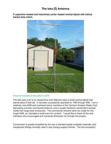
4.3 Antenna ComponentsThe dual dipole antenna is composed of copper wire, coaxial cable, connectors,insulators, toroid cores, a power combiner, rope, support masts, and hardware. Figure4.1a shows the antenna parts provided in the Jove antenna kit while Figure 4.1b showsthe additional hardware required for the dipole support masts. Parts required to build thesupport masts are not provided in the kit. These support structure parts depend upon theheight of the antenna and the type of mast to be assembled. Parts lists are included inmanual sections (4.1-4.2). The estimated PVC antenna mast costs 75; the estimatedmetal antenna mast costs 100.Figure 4.1A shows parts included in the Jove kit. Figure 4.1 B shows additional materials needed tofabricate the support masts.4.4 Radio JOVE Antenna Kit Parts ListTable 4.3 Antenna Parts ListParts included in the Radio JOVE Antenna Kit# Description1 50 ft. (15.24 m) #14 Gauge Bare Copper Wire (7-stranded)1 95 ft. (29 m) RG59U Coaxial Cable (Belden 8241)6 Insulators6 Twist-on F-connectors1 Coaxial cable coupler1 Power combiner / splitter (2-to-1)6 Ferrite toroid cores4 Black plastic tie-wrapsPartsChecklist4.5 Items Supplied in KitCopper Wire is used for the dipole elements. You will build two identical half-wavedipole antennas. The tip-to-tip length (Figure 3.1) of the dipole wires is 23.28 ft.Radio Jove Antenna Manual22
Coaxial Cable (coax) is used to feed the signal from the dipoles to the receiver. The kitis supplied with RG-59/U coax with a velocity factor of 0.66. The lengths of cables usedin the Jove antenna system are tabulated below (Table 4.4).Table 4.4 Coax cable lengths for RG-59/U cable (velocity factor 0.66)AntennaNumber ofCable length inCable lengthPartcables neededwavelengthsC
6. Antenna Mast Assembly 29 6.1 PVC Masts 29 6.2 PVC Mast Assembly (Refer to Figures 6.1, 6.2, and 6.3) 29 6.3 Metal Masts 33 6.4 Metal Mast Assembly (Refer to Figures 6.4 and 6.5) 33 7. Field Setup, Safety and Testing 36 7.1 Weatherproofing the Antenna 36 7.2 Field Setu