Transcription
Machining the AR15Lower Receiver ForgingbyRay BrandesAR Lower Receiver Step-by-Step1
Copyright 2003 Ray-Vin Publishing Co.All rights reserved.First EditionRay-Vin Publishing Co.1844 Mt Cello RdMarianna, Florida USA32448-5365www.ray-vin.com2AR Lower Receiver Step-by-Step
This book is dedicated to my best friend and loving wifeVincentine “Ruby” BrandesAR Lower Receiver Step-by-Step3
I would like to thank the following people for the help they provided inmaking this book possible:Frank White - Compass Lake EngineeringBruce Funkand all the members of AR15.COM4AR Lower Receiver Step-by-Step
ContentsChapter 1 What you need to knowChapter 2 The First SetupChapter 3 HolesChapter 4 The Passenger SideChapter 5 The Buffer EndChapter 6 Pivot Pin DetailsChapter 7 Finishing the Pistol Grip MountChapter 8 Buffer Retainer HoleChapter 9 The Magazine WellChapter 10 The Hammer & Trigger WellChapter 11 Safety Detent & Trigger GuardChapter 12 Finishing UpAppendix: Tools list and alternate setupsAR Lower Receiver Step-by-Step5
Chapter 1What you need to knowIn this book I will explain in simple terms just how I go aboutmachining an AR15 lower receiver from a forging. When I first lookedat the blue print for the Colt lower I was overwhelmed by the complexity of it all. Now, after successfully machining several, it is nothingmore than the combination of many small, simple operations.First of all cutting metal is the easy part of being a machinist. Thedifficult part is holding the work and locating the cutting tool relativeto the work. These two things together are called the setup. We will use10 setups to finish our lower.I use a Bridgport style milling machine with a digital read-out(DRO). With the DRO it is very easy to work using Cartesian coordinates. If you don’t have a DRO, you can still do it, but it will take youa little longer and you must guard against positioning errors. Each fullturn of the handle is usually 0.200” and the usual method for movingto a position is to count turns. You won’t make an error of a fewthousands, it will be .200” or one full turn of the handle. Always touchoff your drill and then check with your scale before putting in the hole.When setting your position always come to the mark by turning thehandle clock wise to eliminate backlash errors. -X, YX AXIS-X,-YY AXIS- X, Y X,-Y 0,0-Throughout this book I will maintain certain conventions. When aposition is noted it will always be the X axis first followed by the Yaxis. The X axis runs left to right and is the long axis on your millingtable. For example, if 0,0 is the pivot pin hole location, then the takedown pin hole will be at 6.375 0.00.There are some special tools you will need to follow my methodof doing this project. A 1-3/16 x 16 tap for the buffer tube is a must.Also a long 3/32 drill and a long 1/8 drill. Also a long 1/4” center drillfor spotting the buffer retainer hole.6AR Lower Receiver Step-by-Step Chapter 1
It is also recommended that you have all the parts for your loweron hand to check for fit and function as the project progresses.There are some key surfaces on the lower that will be called byButt FaceDeckRight CheekLeft CheekNamed Facesname because we will be referring to them often in the text. The deckis the main flat surface that mates with the upper. The butt face (don’tlaugh) is the face that the buttstock mates against. The left cheek is onthe driver’s side and is the face where the trigger & hammer pin holeswill be. The right cheek is on the opposite side. All forgings are not thesame. Measure across the cheeks and record this dimension. You maywant to take several readings and use the average. I will refer to this asdimension Alpha.Dimension ALPHAAR Lower Receiver Step-by-Step Chapter 17
DimensionBravoHelpful fixturesBefore you start cutting on your forging, there are a some fixturesyou will need to make. One is a pair of clamping pads to support andhold the forging for several setups. The other is a little drill guide thattakes the heart-burn out of putting in the bolt release pivot pin hole.Drawings for all of these items may be found in the back of the book,figures 1, 2 and 3. Take the time to make them now. You will regret itif you don’t. After you finish the passenger side clamping pad, measureand record dimension Bravo.Another thing to keep in mind is your serial number. If you aregoing to stamp the number in it is best done while the forging is solidrather than when it is all hollowed out for triggers and magazines. TheBATF does not require a serial number, but they recommend you markthe receiver in such a way that it can be returned to you if lost orstolen. It is better to have a number on the receiver than to try toexplain to the arresting officer that it is legal for you to have a weaponwithout a serial number! The alternative is to take your finished receiver to a trophy shop and have them engrave it to your specifications.This book is offered for educational use only. It is the usersresponsibility to determine if finishing an AR-15 lower receiver isallowed by law in their state and municipality. The author and publisher assume no liability whatsoever.8AR Lower Receiver Step-by-Step Chapter 1
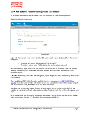
Chapter 2The First SetupWith forgings (as well as castings and weldments) that require finalprecision machining, the big problem is where to start. If you cut too muchoff of one side, there may not be enough material on the other side to cleanup and now you have one expensive piece of scrap. It is like cutting adiamond. You must make the first cut just exactly right in order for everything else to fall in place.(BUTTFACE)This chapter takes you5SURFACES FINISHEDthrough the first setup and the first,IN THIS CHAPTERand most important, cuts. Whenyou complete this chapter, you will 4have five finished surfaces on yourforging.231(DECK)Begin by clamping the forging to your milling machine table using thepassenger side clamping pad. Then indicate the forging true to the x axis.Here is the top view of the setup.AR Lower Receiver Step-by-Step Chapter 29
Now the forging is parallel and aligned to the table in the x axis.We will now cut the five surfaces. But, first we have to locate the piecein order for our machining to line up with the various features on theforging.I like to pick up the round boss where the magazine catch will go.This is a good feature to locate on as it will give both x and y. Use acenter and center it on the boss. You can easily get within .005” byeye. Zero you digital read out. For those without DRO’s, it will takeyou longer and you will have to be more careful, but those are youronly handicaps. Move the spindle to the pivot pin hole location andcheck the alignment with the forging. If it looks good make thisposition your absolute zero.5632.10910Thisis0,0AR Lower Receiver Step-by-Step Chapter 2
.250.750 R1.5757.0007.500Leave this corner sharp!Above are the five surfaces to finish in the first set-up or hold. Iuse a 1” endmill because it makes for easy math. For the 3/4” radius Ix-y it with the 1” endmill in 18 steps (5 degrees each) and it comes outvery smooth.Nothing more needs be said for experienced machinests. However, I will add somethings for the benifit of the beginners. Since youwill be working close to the table, set your spindle stop to keep thecutter from hitting the table. Don’t try to take off all the metal in onecut. Take rough cuts and leave about .010 for the final cut. A light finalcut will deflect the cutter less and give you a better finish. When youthink you are finished cutting, clean all the chips away and take a lookat your work.0.0000.7500.0006.5008.0002.075Above is the tool path for a 1” dia cutter. Onthe right is the table of the 18 steps around the 3/4”radius. The first and last coordinates are the endsof the straight tool 486-6.492-6.496-6.499-6.500AR Lower Receiver Step-by-Step Chapter .938-0.958-0.979-1.00011
3/4RADIUSBUTTFACEDECKTOPFLATMake sure you have done all the cuts scheduled for this setupbefore you break it down.Now that we have established our initial finished surfaces we canhold the forging for the placement of pin holes etc. But before we do,we need to cut a small flat in the bottom of the magazine well to aid inclamping.Put the lower on a couple of 1-2-3 blocks and clamp as showabove. Using a 1/2” cutter make a flat in the middle of the magazinewell, centered and about 3/4” long. Cut this flat in the material thatwill be removed when we cut the magazine well.12AR Lower Receiver Step-by-Step Chapter 2
Here is an alternate method for cutting the clamp flat. Support thelower on a 1-2-3 blocks and using the passenger side clamp pad, clampit to an angle plate. You can also hold the lower in a vise using thedriver side and passenger side pads.If you prefer to work in a vise, take the optional cut shown belowacross the bottom of the trigger guard bosses. When claming on thesebosses, be careful not to overtighten and crush your forging.2.593AR Lower Receiver Step-by-Step Chapter 213
Chapter 3HolesIn this setup you will be putting in the pivot pin hole, take-downpin hole, trigger and hammer holes, safety hole, magazine release hole,bolt release hole and rear trigger guard hole. Also, the safety stops willbe milled along with the magazine release pocket, the bolt releasepocket and one side of the pistol grip mount.0.250Workholding: Put a sturdy angle plate on the mill table andindicate it true to the x axis. To the plate you will clamp the forging fordrilling pin holes etc. Make sure the surface with the two safety stopbumps is about 1/32 above the top of the angle plate. Using the quill,indicate the machined surface on the end of the forging as show belowand clamp tightly.7.500MAKE THIS POINT 0,0EDGE FINDERLocation: Pick up the surface just indicated (butt face) with anedge finder and then the face of the forging that is against the angleplate (deck). Move to the location of the pivot pin (7.500X -.250Y)and zero your DRO. Refer to the drawing “DRIVER SIDE” in theappendix for dimensions for this setup.14AR Lower Receiver Step-by-Step Chapter 3
6.3750.00.0Drill and ream .251 dia. the pivot pin hole through at 0.000-0.000.Now do the same for the take-down pin hole at 6.375-0.000.0.00.4645.5720.0When doing this kind of work it is a wise move to just touch thework with the center drill and then lay your scale on it just to makesure you are in the right place.Next is the hole for the safetyselector. Drill and ream 0.376 diathrough at 5.572-0.464.AR Lower Receiver Step-by-Step Chapter 315
3.6044.4470.00.00.02.188The next hole does not go through. It isfor the spring that keeps the bolt release0.0down. You will probably have to spot face 0.194here to get a flat spot for the drill to start.Drill 5/32 dia. at 3.079-0.194 to 1/32 past thecenterline.Bolt ReleaseHammer0.00.00.5633.079Next is the magazine releasehole. Move to 3.079-0.563. Drillthrough with a #5 drill (0.205”diameter).3.0790.0Next, drill the rear trigger guardhole. It is .125 dia. through at 4.8752.188. Do not drill the forward triggerguard hole from this side. It is only onthe other side.4.875Drill and ream the trigger hole 5/32(0.156) dia. through at 4.447-0.689. Do thesame for the hammer hole at 3.604-0.375.0.00.3750.689TriggerTake-down PinPivot PinMagazine ReleaseSafety SelectorRear Trigger GuardThat concludes the drilling portion for this setup. Check yourwork against the drawing above and be sure you have all eight holes.16AR Lower Receiver Step-by-Step Chapter 3
0.00.2793.0790.0Now we will do a little milling. Since we are in the neighborhoodof the bolt release we will mill the side portion of that groove first.Mount up a 5/32 end mill and set it to stop on the safety bump surfaceas show below. This is as far down as you need to cut the groove.Crank the table down, locate thespindle at 3.079 and mill the bolt releasegrove to 0.279 to the depth set above.This is why that surface needs to be about 1/32 above the top ofthe angle plate.AR Lower Receiver Step-by-Step Chapter 317
0.0Now we will do the safety stops. Chuck a 1/4 dia. cutter and putthe spindle on the Y axis of the safety hole, 0.464. Using a piece ofplain paper, about .004” thick, for feeler gauge, set the depth of yourcutter to be 0.004” above the surface. On this setting mill off the lowerhalf of the safety bumps.0.00.464When you have this done, go ahead and drop the safety in andcheck the fit. You have two minutes to stop smiling and get on to thenext step.18AR Lower Receiver Step-by-Step Chapter 3
5/32 down from this surface3.1971.9380.0The magazine release lays in a slot you will mill using the same1/4 inch cutter. The depth of this cut is 5/32 from the surface. Thecoordinates are 1.938-0.563 to 3.197-0.563.0.00.563Go ahead, drop the magazine release in place. It should be closeto flush with the reference surface. When you stop smiling, we can getgoing with the pistol-grip pocket.AR Lower Receiver Step-by-Step Chapter 319
Reference surface5.2035.4530.0Chuck a 1/2” dia. cutter and touch off on the reference surface.My forging is 0.864 thick at this point so it will be 0.432 to thecenterline. The face of the grip pad is 3/16 up from the centerline sowe need to subtract .1875 from .432 which gives .244 inches downfrom the reference surface to the bottom of the cut. You will need tomake your own calculations based on the thickness of your particularforging.0.01.0661.316You can set your incremental zero at 5.453-1.316 which is thecorner of the pocket. Stay away by five or ten thousandths as yourough down to within 0.005” of the finished depth. Then set yourfinished depth and mill the sides and bottom finished in one pass. Becareful not to run into your clamp!20AR Lower Receiver Step-by-Step Chapter 3
Check ListBefore breaking the setup, double check that all the opperationsfor this setup have been ETYSTOPSTAKE-DOWNPINA good habit to get into is this. When you think you are finished,clean off the machine of chips and tools etc. instead of rushing toremove your work-piece. This gives you some time to think about it.Nothing is as frustrating as having to re-setup something because youmissed a hole.AR Lower Receiver Step-by-Step Chapter 321
Chapter 4The Passenger SideThis setup is basically the same as the previous one, except that wewill be putting the passenger side of the reciever up. This chapter deals withspot facing the take down pin hole, milling off the front of the pivot pindetent channel, drilling the vent hole for the pivot pin detent, finishing themagazine release, drilling the front trigger guard hole and milling the otherside of the pistol grip mount.The SetupWorkholding: As in chapter 3, clamp the forging to the angle plate(passenger side up) and indicate true the butt face using the quill.Location: Edge find the buttface and the deck. Move 7.500-X and.250-Y (to the pivot pin location) and set this to zero-zero. Refer to drawing “PASSENGER SIDE” in the appendix for this setup.22AR Lower Receiver Step-by-Step Chapter 4
0.0000.0006.375First operation is to spot face the take-down pin hole. Chuck a 7/16”dia. endmill and move over the right cheek. Set your elevation wheel at zeroand bottom the cutter on the right cheek for the Z reference. Move to6.375-0.000 and spot face to 0.411” from the centerline.You can check the fit, but there isn’t much to check for. Just see thatthe spot face is big enough for the pin head.AR Lower Receiver Step-by-Step Chapter 423
0.0430.0000.1451.055Now use a 3/8” cutter and move to 0.043 x (to the right of the pivotpin hole and mill off the face at a setting of 0.522 from the centerline. Checkthat the pivot pin fits nicely before moving on.0.52224AR Lower Receiver Step-by-Step Chapter 4
000.00.4630.6630.0003.079Chuck a 5/16 endmill and prepare to mill the pocket for the magazinerelease button. The drawing calls for this to be 0.318 wide by 0.515 long,centered on the hole at 3.079-0.563. You will mill from roughly 0.663-Y to0.463-Y to a depth of 0.069 past the centerline. Before moving on, checkthe fit with the mag release button. You don’t want this to be tight.AR Lower Receiver Step-by-Step Chapter 425
The magazine release hole needs to be relieved for the spring. Youmay be intimidated by cutting the mag well, but this operation is what scaresme the most!You have to cut to within 0.054” of the bar slot on the other side andhere is how to do it.Hold the mag release in the bar slot the wrong way around, measuredown to it from the button surface and record your measurement. It shouldbe close to 15/16” (0.937”). From this value subtract 0.054” and recordthe result.Now chuck a 5/16” end mill and bring the quill down to the stop.Raise the table until the end mill touches off on the button surface. Set yourelevation dial at zero. Raise the quill and then bring the table up by the resultyou recorded earlier. Position the spindle at 3.079-0.563 and with thespindle off, bring the cutter down until it bottoms on the metal to be cut.Check your quill stop, you should have about 1/4” to go. If you have more,recheck all your measurements!Button surface0.0000.563OOPS!CHECKAGAIN26AR Lower Receiver Step-by-Step Chapter 40.0003.079GOOD!
The next item in this setup is the forward trigger guard hole. Locate thespindle at 3.031 x 2.188 and drill a 1/8” hole about 1/4” deep. Don’t drill itthrough.0.0002.1880.0003.031Here is the lower being held by the alternate method in a vise. Afteryou drill this hole, go back in with a #2 center drill and cut a nice chamferon the edge.0.0001.055One little hole that is easy to overlook is the breather for the takedown pin detent. Locate your spindle at 1.055-0.000 and drill a 5/64(0.078) diameter hole about 1/8” deep. The hole it will be venting isn’t thereyet so don’t go too deep.1.125AR Lower Receiver Step-by-Step Chapter 427
5.4530.0001.0661.3160.0005.203As in chapter three to cut the passenger side of the pistol grip mountchuck a 1/2” dia. cutter. No need to touch off, just take a light cut thenmeasure the thickness and adjust from there for a finished size of 0.375”.You can set your incremental zero at 5.453-1.316 which is the cornerof the pocket. Stay away by five or ten thousandths as you rough down towithin 0.005” of the finished depth. Then set your finished depth and mill thesides and bottom finished in one pass. Be careful not to run into your clamp!If you use the alternate holding method using a vise, be sure to leavethe area to be milled clear of the jaws as shown above, not like on theopposite page.28AR Lower Receiver Step-by-Step Chapter 4
Spot facetake-down pinholeMill pistolgrip pocketDrillpivot pin ventDrill and millmagazine releaseMill front of pivot pindetent channelDrill fronttrigger guardholeBefore you break your setup, check your work!AR Lower Receiver Step-by-Step Chapter 429
Chapter 5The Buffer EndIn this setup we will put in the hole for the bolt release pivot,take-down pin detent hole, the buttstock key hole and bore and threadthe hole for the buffer tube. Also, two more surfaces on the pistol gripmount will get finished.0.000Work Holding: Once again,clamp the top face of the receiverto the angle plate in the orientation show at the right with thebuffer end of the receiver up.Indicate it true and tighten theclamps.Locating the spindle: Withyou edge finder, locate the centerof the .375 pistol grip mount. Ifyou prefer, find the center usingthe left and right cheeks. This willbe zero on the X axis. Edge findthe face of the angle plate andmake this surface zero. This willbe your zero on the Y axis.0.00030AR Lower Receiver Step-by-Step Chapter 5
0.6180.000Locate the spindle at 0.618-.188 and chuckthat long 3/32 drill. Here is where you will usethat little block I told you to make in chapter one.Hold the block tightly against the angle plate andthe forging. The drill should line up exactly withthe hole in the block. Holding the block tightly,drill the hole through the lug on the forging.Drilling this hole any other way will drive younuts!0.0000.188AR Lower Receiver Step-by-Step Chapter 531
320.0000.331Next is the hole for the take down pin detent.Locate your spindle at 0.331-0.250 and drill a 3/32”hole down to the take down pin hole.When drilling deep holes, a poor start will getthe drill walking off right away. Start the hole withthe drill choked up close in the chuck. Once thehole is started, chuck the bit normally and finish thehole.0.0000.250AR Lower Receiver Step-by-Step Chapter 5
0.000Now for the buffer tube hole.Locate your spindle at 0.000-0.625 andbore a 1.125” hole through the tang.0.6250.000You can put a tool in your boringhead or flycutter to put a nice 45 degreechamfer on the corner.AR Lower Receiver Step-by-Step Chapter 533
If you have the 1-3/16 - 16 tap go ahead and tap the hole. Put acenter in the spindle to keep the tap aligned and with a light pressureon the down handle turn the tap with a wrench. If you don’t have a tap,you can single-point the thread in a lathe, see the appendix.34AR Lower Receiver Step-by-Step Chapter 5
0.000At 0.000-0.375 spot and bore the buttstock anti-rotation hole. Thesize of this hole is 0.499 plus .004 minus nothing. If you drill a pilothole first, your 1/2” drill should not cut oversize. It is important not todrill this hole too deep since the buffer retainer hole will go just on theother side. I like to drill a 1/4” hole 1/4” deep and then go in with a0.500” diameter end mill about .225”.BUFFERRETAININGHOLE(CHAP 8)0.3750.200AR Lower Receiver Step-by-Step Chapter 535
Chuck up a cutter and touch off on the butt face. I use printerpaper that is 0.004” thick and set my dial that amount before the zero.36AR Lower Receiver Step-by-Step Chapter 5
Mill flush with thissurfaceThe first surface to mill is 1.050” down from the butt face. Milluntil you are flush with the side faces of the pistol grip mount.The next surface should be 1.250” further down and 0.930 awayfrom the surface just milled. Move to your depth slowly and make yourcut flush with the existing surfaces.0.0001.3162.246Mill flush to thissurface0.000(0.930)1.050(1.250)2.300AR Lower Receiver Step-by-Step Chapter 537
Once again, before moving on, check that all operations arecomplete before breaking this setup.Bore &thread buffertube holeDrill take-downpin detent holeDrill stock antirotation holeMill first pistolgrip flatDrill boltreleasepivot holeMill secondpistol grip flat0.3310.6251-3/16 - 16 TAP THRU0.6250.1880.250DECK0.3753/32 DRILL THRU383/32 DRILL THRU TOTAKE-DOWN HOLE.500 DIA. BORE X.200 DEEPAR Lower Receiver Step-by-Step Chapter 5
Chapter 6Pivot Pin DetailsIn this chapter we will put in the pivot pin detent hole and millout the pivot pin boss where the upper receiver goes in.Once again we will use our passenger side plate to hold the work.You need to know the exact thickness of the side plate where it contacts the cheek of the receiver so if you havn’t miked it yet, do it nowand write the dimension down on the passenger side plate drawing.Workholding: Clamp the forging to the angle plate using thepassenger side plate. Put the butt face against the table. Indicate thedeck true to the quill.Location: Edge find the deck and move in 0.250 and set X zero.Edge find the face of the angle plate and move out the thickness of theside plate (that you just recorded) plus half the width of your forging(dim. alpha / 2) and set Y zero.AR Lower Receiver Step-by-Step Chapter 639
0.000First in will be the pivot pin detent hole. Position your spindle at0.000-0.583 and center drill with a #0 center drill. Choke a 3/32 drilland start the hole. Chuck the bit normally and finish the hole to 1.125”deep from the surface.0.5831.12540AR Lower Receiver Step-by-Step Chapter 6
For the slot where the upper and lower meet, chuck a 3/8” endmill. Put a pin in the take-down hole and touch off on the top of thepin. From here you will go down 0.385” to the finished surface.Mill down along the center-line 3/8” past the pin hole until youare within 0.010” of the finished depth. Then widen the slot equally onboth sides to 0.500 .004 -.000.To check if you are deep enough, put the pivot pin in the hole andsee that a 1/8” dowl pin fits freely between the pivot-pin and thereceiver. An even better check is to see if your upper fits.0.3750.5830.500AR Lower Receiver Step-by-Step Chapter 641
Chapter 6 check list. Check that all operations are complete beforemoving on.Drill pivot-pindetent hole42Mill pivot recessAR Lower Receiver Step-by-Step Chapter 6
Chapter 7Finishing the Pistol Grip MountWe will now finish up the pistol grip mount. First we will mill the30 degree face and then drill and tap 1/4-28 for the pistol grip screw.Workholding: This is an easy setup (if your milling machine islevel!). Set your combination protractor to 60 degrees and using thenest plate, clamp the forging to the angle plate with the butt face at 60degrees. Tap until the bubble is centered and then add a second clamp.Re-check the angle after tightening the second clamp.Location: Find the center lineas usual and then put a .250 pin inthe take down hole. Edge find thepin then move to its center and setzero. Chuck a 1/2” endmill and setthe spindle stop and bring thespindle down and lock it against thestop. Raise the table until the cuttertouches the pin and zero the elevation dial.AR Lower Receiver Step-by-Step Chapter 743
From the pin center-line to the surface to be milled is 1.228”.Since we touched off on the top of the pin we will subtract the raidus,.125” from the 1.400” giving us 1.103” . Lower the table by thisamount and mill the angle face of the pistol grip mount.Locate the spindle at 1.400-0.000. Then drill with a #3 drill about1-1/4” deep. Counter sink to 5/16” diameter (this helps getting thescrew started) and then tap 1/4-28. That’s it for this setup. Clean themachine and then go to the checklist on the next page before breakingdown.44AR Lower Receiver Step-by-Step Chapter 7
Chapter 7 check list. Check that allthe features are compleated beforebreaking your set-up.Mill pistol gripbottom faceDrill and tap 1/4-28pistol grip mountinghole1.4001.1031.22860 AR Lower Receiver Step-by-Step Chapter 745
Chapter 8Buffer Retainer HoleIn this chapter we will drill the buffer tube retainer hole and in asimilar and closely related setup put a small chamfer on the back of thereceiver. The buffer retainer needs to be in just the right spot. Thebuffer tube itself keeps the retainer in place, but must allow the tip ofthe retainer to extend up to stop the buffer. Thanks again to moderncomputer graphics for helping us locate this hole easily.Workholding: Set your protractor for 6 degrees and clamp theforging against the angle plate using the clamping pad. Tap the forginguntil the buble is level and add a second clamp. Re-check the angleafter tightening the second clamp.Locating: Edgefind thecorner at the top of the buttface.Alternatly, you can pick up thecenter of the take-down pin, butsince the detent hold is relativeto the buffer tube, it is best topick up from the surface thebuffer tube shoulders against.46AR Lower Receiver Step-by-Step Chapter 8
Since you will be drilling intothe buffer tube threads, the investment in a long #3 center drill iswell worth it. Move to the locationand spot the hole to the full diameter (.250) of the center drill.Put a 0.250 dowel pin in thetake down hole and move thespindle over it with your drill inplace. Bring the quill down to thestop and then bring the table upuntil the drill touches the pin. Apaper shim is always handy andmakes a good feeler. Set yourelevation dial to zero and thencome up 0.639”.You don’t want to make amistake here by drilling through byaccident. Double check your depthsetting by moving to X-zero andbring the drill down to the stop andlook in to see; first-that the drill tipwill not break out of the forging atthe bottom and second-that yourdrill chuck will not run into the topof the buffer tube ring.AR Lower Receiver Step-by-Step Chapter 847
Always check for fit with the part before breaking the setup. I hada 1/4” drill that drilled just a half thousandth small and the plungerwouldn’t go in. This is the best time to find out if the hole is tight. Iopened it up with a .251” reamer and the fit was perfect!0.6910.5956 (THREADSSIMPLIFIEDFORCLAIRITY)0.63948AR Lower Receiver Step-by-Step Chapter 8
Chapter 8-1/2Charging Handle ReliefThis was originally another chapter, but I combined it here because the setup is so similar and the location and cut are simple.Workholding: Clamp the lower at 15 degrees. Use your protractor and clamp it up and tap until the bubble is centered. Then add asecond clamp.Location: No location required for this setup. Just come downwith your cutter until you touch the corner and then come down another .035”. If you scheduled your work right, it might be a good timeto go have a beer!0.13615 0.035AR Lower Receiver Step-by-Step Chapter 849
50liefle ReHandgingCharBuffer RetainerHoleClean your machine and then check your work!AR Lower Receiver Step-by-Step Chapter 8
Chapter 9The Magazine WellThis chapter deals exclusively with the magazine well. I havedone some very minor re-design of the profile here to make it easier tomachine in the home shop. This profile works just fine and saves timeand heartburn as well! Don’t let cutting the mag well freighten you, itis easier than you think! The process is only five steps:One: Drill 1/8” diameter holes in all the corners. These will createthe corner fillets.Two: Then we will drill rough holes to remove most of the stockthat is co
Begin by clamping the forging to your milling machine table using the passenger side clamping pad. Then indicate the forging true to the x axis. Chapter 2 The First Setup With forgings (as well as castings and weldments) that require final precision machinin