Transcription
CHAPTER 2LAN RedundancyObjectivesUpon completion of this chapter, you will be able to answer the following questions:nnnnnnWhat are the issues that you should be concerned with when implementing a redundantnetwork?nnHow does IEEE 802.1D STP operate?What are the different varieties of spanningtree?How does PVST operate in a switched LANenvironment?How does Rapid PVST operate in aswitched LAN environment?nnnWhat are the commands to configure RapidPVST in a switched LAN environment?What are the common STP configurationissues?What are the purpose and operation of FirstHop Redundancy Protocols?What are the different varieties of First HopRedundancy Protocols?What are the commands to verify HSRP andGLBP implementations?What are the commands to configure PVST in a switched LAN environment?Key TermsThis chapter uses the following key terms. You can find the definitions in the Glossary.First Hop Redundancy Protocols(FHRP) page 51broadcast storm page 54time to live (TTL) page 54root bridge page 59bridge protocol data unit (BPDU) page 59blocking state page 60Rapid Spanning Tree Protocol (RSTP)page 61Multiple Spanning Tree Protocol(MSTP) page 6102 SNCG 3282 r2a.indd 49IEEE-802.1D-2004 page 61bridge ID (BID) page 61extended system ID page 62root port page 62designated port page 63alternate and backup port page 63disabled port page 63default port cost page 64bridge priority page 74Common Spanning Tree (CST) page 782/12/14 3:16 PM
50Routing and Switching Essentials Companion GuidePVST page 78point-to-point link page 89PortFast page 78shared link page 89BPDU guard page 78Hot Standby Router Protocol (HSRP)page 109IEEE 802.1w (RSTP) page 78Rapid PVST page 78listening state page 82learning state page 82forwarding state page 82disabled state page 82Virtual Router Redundancy Protocol(VRRP) page 110Gateway Load Balancing Protocol(GLBP) page 110ICMP Router Discovery Protocol (IRDP)page 110edge port page 8702 SNCG 3282 r2a.indd 502/12/14 3:16 PM
Chapter 2: LAN Redundancy51Introduction (2.0.1.1)Network redundancy is a key to maintaining network reliability. Multiple physicallinks between devices provide redundant paths. The network can then continue tooperate when a single link or port has failed. Redundant links can also share the traffic load and increase capacity.Multiple paths need to be managed so that Layer 2 loops are not created. The bestpaths are chosen, and an alternate path is immediately available should a primarypath fail. The Spanning Tree Protocols are used to manage Layer 2 redundancy.Redundant devices, such as multilayer switches or routers, provide the capability fora client to use an alternate default gateway should the primary default gateway fail.A client can now have multiple paths to more than one possible default gateway.First Hop Redundancy Protocols are used to manage how a client is assigned adefault gateway, and to be able to use an alternate default gateway should the primary default gateway fail.This chapter focuses on the protocols used to manage these forms of redundancy.It also covers some of the potential redundancy problems and their symptoms.Class Activity 2.0.1.2: Stormy TrafficIt is your first day on the job as a network administrator for a small- to mediumsized business. The previous network administrator left suddenly after a networkupgrade took place for the business.During the upgrade, a new switch was added. Since the upgrade, many employeescomplain that they are having trouble accessing the Internet and servers on yournetwork. In fact, most of them cannot access the network at all. Your corporatemanager asks you to immediately research what could be causing these connectivityproblems and delays.So you take a look at the equipment operating on your network at your main distribution facility in the building. You notice that the network topology seems to bevisually correct and that cables have been connected correctly, routers and switchesare powered on and operational, and switches are connected together to providebackup or redundancy.However, one thing you do notice is that all of your switches’ status lights are constantly blinking at a very fast pace to the point that they almost appear solid. Youthink you have found the problem with the connectivity issues your employees areexperiencing.02 SNCG 3282 r2a.indd 512/12/14 3:16 PM
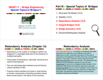
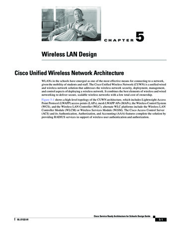
52Scaling Networks Companion GuideUse the Internet to research STP. As you research, take notes and describenBroadcast stormnSwitching loopsnThe purpose of STPnVariations of STPComplete the reflection questions that accompany the PDF file for this activity.Save your work and be prepared to share your answers with the class.Spanning Tree Concepts (2.1)This section focuses on the purpose and operation of the Spanning Tree Protocol.Purpose of Spanning Tree (2.1.1)STP provides the mechanism to have redundant links at Layer 2 while avoiding thepotential for loops and MAC address database instability.Redundancy at OSI Layers 1 and 2 (2.1.1.1)The three-tier hierarchical network design that uses core, distribution, and accesslayers with redundancy attempts to eliminate a single point of failure on the network. Multiple cabled paths between switches provide physical redundancy in aswitched network. This improves the reliability and availability of the network. Having alternate physical paths for data to traverse the network makes it possible forusers to access network resources, despite path disruption.The following steps explain how redundancy works in the topology shown inFigure 2-1.1. PC1 is communicating with PC4 over a redundant network topology.2. When the network link between S1 and S2 is disrupted, the path between PC1and PC4 is automatically adjusted to compensate for the disruption (shown inFigure 2-1).3. When the network connection between S1 and S2 is restored, the path is thenreadjusted to route traffic directly from S2 to S1 to get to PC4.NoteTo view an animation of these steps, refer to the online course.02 SNCG 3282 r2a.indd 522/12/14 3:16 PM
Chapter 2: LAN Redundancy53Figure 2-1 Redundancy in a Hierarchical NetworkFor many organizations, the availability of the network is essential to supportingbusiness needs; therefore, the network infrastructure design is a critical business element. Path redundancy is a solution for providing the necessary availability of multiple network services by eliminating the possibility of a single point of failure.NoteThe OSI Layer 1 redundancy is illustrated using multiple links and devices, but more than justphysical planning is required to complete the network setup. For the redundancy to work ina systematic way, the use of OSI Layer 2 protocols such as STP is also required.Redundancy is an important part of hierarchical design for preventing disruption ofnetwork services to users. Redundant networks require adding physical paths, butlogical redundancy must also be part of the design. However, redundant paths in aswitched Ethernet network can cause both physical and logical Layer 2 loops.Logical Layer 2 loops can occur because of the natural operation of switches, specifically, the learning and forwarding process. When multiple paths exist between twodevices on a network, and there is no spanning tree implementation on the switches,a Layer 2 loop occurs. A Layer 2 loop can result in three primary issues:n02 SNCG 3282 r2a.indd 53MAC database instability: Instability in the content of the MAC address tableresults from copies of the same frame being received on different ports ofthe switch. Data forwarding can be impaired when the switch consumes theresources that are coping with instability in the MAC address table.2/12/14 3:16 PM
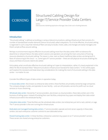
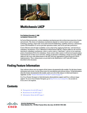
54Scaling Networks Companion GuidennBroadcast storms: Without some loop-avoidance process, each switch can floodbroadcasts endlessly. This situation is commonly called a broadcast storm.Multiple frame transmission: Multiple copies of unicast frames can be deliveredto destination stations. Many protocols expect to receive only a single copy ofeach transmission. Multiple copies of the same frame can cause unrecoverableerrors.Issues with Layer 1 Redundancy: MAC Database Instability (2.1.1.2)Ethernet frames do not have a time to live (TTL) attribute, like IP packets. As aresult, if there is no mechanism enabled to block continued propagation of theseframes on a switched network, they continue to propagate between switches endlessly, or until a link is disrupted and breaks the loop. This continued propagationbetween switches can result in MAC database instability. This can occur because ofbroadcast frames forwarding.Broadcast frames are forwarded out all switch ports, except the original ingress port.This ensures that all devices in a broadcast domain are able to receive the frame. Ifthere is more than one path for the frame to be forwarded out, an endless loop canresult. When a loop occurs, it is possible for the MAC address table on a switch toconstantly change with the updates from the broadcast frames, resulting in MACdatabase instability.The following steps demonstrate the MAC database instability issue. Figure 2-2shows a snapshot during Step 4.1. PC1 sends out a broadcast frame to S2. S2 receives the broadcast frame onF0/11. When S2 receives the broadcast frame, it updates its MAC address tableto record that PC1 is available on port F0/11.2. Because it is a broadcast frame, S2 forwards the frame out all ports, includingTrunk1 and Trunk2. When the broadcast frame arrives at S3 and S1, they updatetheir MAC address tables to indicate that PC1 is available out port F0/1 on S1and out port F0/2 on S3.3. Because it is a broadcast frame, S3 and S1 forward the frame out all ports,except the ingress port. S3 sends the broadcast frame from PC1 to S1. S1 sendsthe broadcast frame from PC1 to S3. Each switch updates its MAC address tablewith the incorrect port for PC1.4. Each switch again forwards the broadcast frame out all of its ports, except theingress port, resulting in both switches forwarding the frame to S2 (shown inFigure 2-2).02 SNCG 3282 r2a.indd 542/12/14 3:16 PM
Chapter 2: LAN Redundancy55Figure 2-2 MAC Database Instability Example5. When S2 receives the broadcast frames from S3 and S1, the MAC addresstable is updated again, this time with the last entry received from the other twoswitches.NoteTo view an animation of these steps, refer to the online course.This process repeats over and over again until the loop is broken by physically disconnecting the connections causing the loop or powering down one of the switchesin the loop. This creates a high CPU load on all switches caught in the loop. Becausethe same frames are constantly being forwarded back and forth between all switchesin the loop, the CPU of the switch must process a lot of data. This slows down performance on the switch when legitimate traffic arrives.A host caught in a network loop is not accessible to other hosts on the network.Additionally, because of the constant changes in the MAC address table, the switchdoes not know out of which port to forward unicast frames. In the previous example, the switches will have the incorrect ports listed for PC1. Any unicast frame destined for PC1 loops around the network, just as the broadcast frames do. More andmore frames looping around the network eventually create a broadcast storm.02 SNCG 3282 r2a.indd 552/12/14 3:16 PM
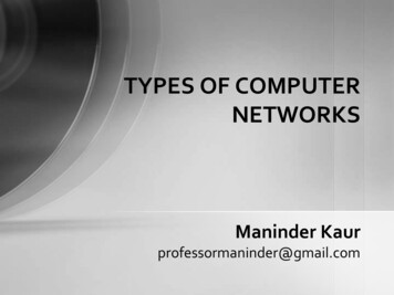
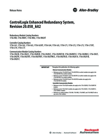
56Scaling Networks Companion GuideIssues with Layer 1 Redundancy: Broadcast Storms (2.1.1.3)A broadcast storm occurs when there are so many broadcast frames caught in aLayer 2 loop that all available bandwidth is consumed. Consequently, no bandwidthis available for legitimate traffic and the network becomes unavailable for data communication. This is an effective denial of service.A broadcast storm is inevitable on a looped network. As more devices send broadcasts over the network, more traffic is caught within the loop, consuming resources.This eventually creates a broadcast storm that causes the network to fail.There are other consequences of broadcast storms. Because broadcast traffic is forwarded out every port on a switch, all connected devices have to process all broadcast traffic that is being flooded endlessly around the looped network. This cancause the end device to malfunction because of the high processing requirements forsustaining such a high traffic load on the NIC.The following steps demonstrate the broadcast storm issue. Figure 2-3 shows thefinal result during Step 6.1. PC1 sends a broadcast frame out onto the looped network.2. The broadcast frame loops between all the interconnected switches on thenetwork.3. PC4 also sends a broadcast frame out on to the looped network.4. The PC4 broadcast frame also gets caught in the loop between all the intercon-nected switches, just like the PC1 broadcast frame.5. As more devices send broadcasts over the network, more traffic is caught withinthe loop, consuming resources. This eventually creates a broadcast storm thatcauses the network to fail.6. When the network is fully saturated with broadcast traffic that is loopingbetween the switches, new traffic is discarded by the switch because it is unableto process it. In Figure 2-3, S2 is now discarding additional frames.NoteTo view an animation of these steps, refer to the online course.Because devices connected to a network are regularly sending out broadcast frames,such as ARP requests, a broadcast storm can develop in seconds. As a result, when aloop is created, the switched network is quickly brought down.02 SNCG 3282 r2a.indd 562/12/14 3:16 PM
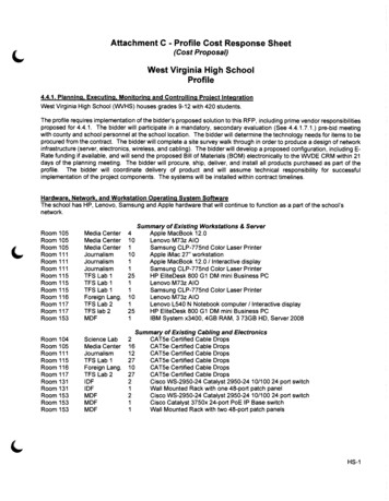
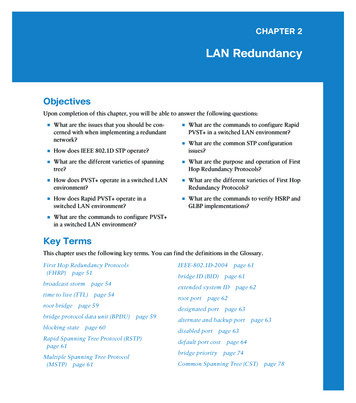
Chapter 2: LAN Redundancy57Figure 2-3 Broadcast StormsIssues with Layer 1 Redundancy: Duplicate UnicastFrames (2.1.1.4)Broadcast frames are not the only type of frames that are affected by loops. Unicastframes sent onto a looped network can result in duplicate frames arriving at the destination device.The following steps demonstrate the duplicate unicast frames issue. Figure 2-4shows a snapshot during Step 5 and Step 6.1. PC1 sends a unicast frame destined for PC4.2. S2 does not have an entry for PC4 in its MAC table, so it floods the unicastframe out all switch ports in an attempt to find PC4.3. The frame arrives at switches S1 and S3.4. S1 does have a MAC address entry for PC4, so it forwards the frame outto PC4.5. S3 also has an entry in its MAC address table for PC4, so it forwards the unicastframe out Trunk3 to S1.6. S1 receives the duplicate frame and forwards the frame out to PC4.7. PC4 has now received the same frame twice.02 SNCG 3282 r2a.indd 572/12/14 3:16 PM
58Scaling Networks Companion GuideFigure 2-4 S1 and S3 Send Duplicate Frame to PC4NoteTo view an animation of these steps, refer to the online course.Most upper-layer protocols are not designed to recognize, or cope with, duplicatetransmissions. In general, protocols that make use of a sequence-numbering mechanism assume that the transmission has failed and that the sequence number hasrecycled for another communication session. Other protocols attempt to hand theduplicate transmission to the appropriate upper-layer protocol to be processed andpossibly discarded.Layer 2 LAN protocols, such as Ethernet, lack a mechanism to recognize and eliminate endlessly looping frames. Some Layer 3 protocols implement a TTL mechanismthat limits the number of times a Layer 3 networking device can retransmit a packet.Lacking such a mechanism, Layer 2 devices continue to retransmit looping trafficindefinitely. A Layer 2 loop-avoidance mechanism, STP, was developed to addressthese problems.To prevent these issues from occurring in a redundant network, some type of spanning tree must be enabled on the switches. Spanning tree is enabled, by default, onCisco switches to prevent Layer 2 loops from occurring.Packet TracerActivity02 SNCG 3282 r2a.indd 58Packet Tracer Activity 2.1.1.5: Examining a Redundant DesignIn this activity, you will observe how STP operates, by default, and how it reactswhen faults occur. Switches have been added to the network “out of the box.” Cisco2/12/14 3:16 PM
Chapter 2: LAN Redundancy59switches can be connected to a network without any additional action requiredby the network administrator. For the purpose of this activity, the bridge prioritywas modified.STP Operation (2.1.2)STP uses the concepts of a root bridge, port roles, and path costs to calculate whichlinks to use in a redundant topology.Spanning Tree Algorithm: Introduction (2.1.2.1)Redundancy increases the availability of the network topology by protecting thenetwork from a single point of failure, such as a failed network cable or switch.When physical redundancy is introduced into a design, loops and duplicate framesoccur. Loops and duplicate frames have severe consequences for a switched network. The Spanning Tree Protocol (STP) was developed to address these issues.STP ensures that there is only one logical path between all destinations on the network by intentionally blocking redundant paths that could cause a loop. A port isconsidered blocked when user data is prevented from entering or leaving that port.This does not include bridge protocol data unit (BPDU) frames that are used bySTP to prevent loops. Blocking the redundant paths is critical to preventing loops onthe network. The physical paths still exist to provide redundancy, but these paths aredisabled to prevent the loops from occurring. If the path is ever needed to compensate for a network cable or switch failure, STP recalculates the paths and unblocksthe necessary ports to allow the redundant path to become active.In Figure 2-5, all switches have STP enabled:Figure 2-5 Normal STP Operation02 SNCG 3282 r2a.indd 592/12/14 3:16 PM
60Scaling Networks Companion Guide1. PC1 sends a broadcast out onto the network.2. S2 is configured with STP and has set the port for Trunk2 to a blocking state, asshown in Figure 2-5. The blocking state prevents ports from being used to forward user data, thus preventing a loop from occurring. S2 forwards a broadcastframe out all switch ports, except the originating port from PC1 and the port forTrunk2.3. S1 receives the broadcast frame and forwards it out all of its switch ports, whereit reaches PC4 and S3. S3 forwards the frame out the port for Trunk2 and S2drops the frame. The Layer 2 loop is prevented.NoteTo view an animation of these steps, refer to the online course.In Figure 2-6, STP recalculates the path when a failure occurs.Figure 2-6 STP Compensates for Network Failure1. PC1 sends a broadcast out onto the network.2. The broadcast is then forwarded around the network, just as in the previousanimation.3. The trunk link between S2 and S1 fails, resulting in the previous path beingdisrupted.4. S2 unblocks the previously blocked port for Trunk2 and allows the broadcasttraffic to traverse the alternate path around the network, permitting communication to continue. If this link comes back up, STP reconverges and the port on S2is again blocked.02 SNCG 3282 r2a.indd 602/12/14 3:16 PM
Chapter 2: LAN Redundancy61NoteTo view an animation of these steps, refer to the online course.STP prevents loops from occurring by configuring a loop-free path through the network using strategically placed “blocking-state” ports. The switches running STP areable to compensate for failures by dynamically unblocking the previously blockedports and permitting traffic to traverse the alternate paths.Up to now, we have used the term Spanning Tree Protocol and the acronym STP.The usage of the Spanning Tree Protocol term and the STP acronym can be misleading. Many professionals generically use these to refer to various implementationsof spanning tree, such as Rapid Spanning Tree Protocol (RSTP) and MultipleSpanning Tree Protocol (MSTP). In order to communicate spanning tree conceptscorrectly, it is important to refer to the particular implementation or standard incontext. The latest IEEE documentation on spanning tree, IEEE-802-1D-2004,says “STP has now been superseded by the Rapid Spanning Tree Protocol (RSTP).”So one sees that the IEEE uses “STP” to refer to the original implementation ofspanning tree and “RSTP” to describe the version of spanning tree specified inIEEE-802.1D-2004. In this book, when the original Spanning Tree Protocol is thecontext of a discussion, the phrase “original 802.1D spanning tree” is used to avoidconfusion.NoteSTP is based on an algorithm invented by Radia Perlman while working for Digital EquipmentCorporation, and published in the 1985 paper “An Algorithm for Distributed Computationof a Spanning Tree in an Extended LAN.”Spanning Tree Algorithm: Port Roles (2.1.2.2)IEEE 802.1D STP uses the Spanning Tree Algorithm (STA) to determine whichswitch ports on a network must be put in blocking state to prevent loops fromoccurring. The STA designates a single switch as the root bridge and uses it as thereference point for all path calculations. In Figure 2-7, the root bridge (switch S1)is chosen through an election process. All switches participating in STP exchangeBPDU frames to determine which switch has the lowest bridge ID (BID) on the network. The switch with the lowest BID automatically becomes the root bridge for theSTA calculations.NoteFor simplicity, assume until otherwise indicated that all ports on all switches are assigned toVLAN 1. Each switch has a unique MAC address associated with VLAN 1.02 SNCG 3282 r2a.indd 612/12/14 3:16 PM
62Scaling Networks Companion GuideFigure 2-7 STP AlgorithmA BPDU is a messaging frame exchanged by switches for STP. Each BPDU contains aBID that identifies the switch that sent the BPDU. The BID contains a priority value,the MAC address of the sending switch, and an optional extended system ID. Thelowest BID value is determined by the combination of these three fields.After the root bridge has been determined, the STA calculates the shortest path to it.Each switch uses the STA to determine which ports to block. While the STA determines the best paths to the root bridge for all switch ports in the broadcast domain,traffic is prevented from being forwarded through the network. The STA considersboth path and port costs when determining which ports to block. The path costs arecalculated using port cost values associated with port speeds for each switch portalong a given path. The sum of the port cost values determines the overall path costto the root bridge. If there is more than one path to choose from, STA chooses thepath with the lowest path cost.When the STA has determined which paths are most desirable relative to eachswitch, it assigns port roles to the participating switch ports. The port roles describetheir relation in the network to the root bridge and whether they are allowed toforward traffic:n02 SNCG 3282 r2a.indd 62Root ports: Switch ports closest to the root bridge. In Figure 2-7, the root porton S2 is F0/1 configured for the trunk link between S2 and S1. The root porton S3 is F0/1, configured for the trunk link between S3 and S1. Root ports areselected on a per-switch basis.2/12/14 3:16 PM
Chapter 2: LAN Redundancynnn63Designated ports: All nonroot ports that are still permitted to forward trafficon the network. In Figure 2-7, switch ports (F0/1 and F0/2) on S1 are designatedports. S2 also has its port F0/2 configured as a designated port. Designated portsare selected on a per-trunk basis. If one end of a trunk is a root port, the otherend is a designated port. All ports on the root bridge are designated ports.Alternate and backup ports: Alternate ports and backup ports are configuredto be in a blocking state to prevent loops. In the figure, the STA configuredport F0/2 on S3 in the alternate role. Port F0/2 on S3 is in the blocking state.Alternate ports are selected only on trunk links where neither end is a root port.Notice in Figure 2-7 that only one end of the trunk is blocked. This allows forfaster transition to a forwarding state, when necessary. (Blocking ports onlycome into play when two ports on the same switch are connected to each otherthrough a hub or single cable.)Disabled ports: A disabled port is a switch port that is shut down.Spanning Tree Algorithm: Root Bridge (2.1.2.3)As shown in Figure 2-8, every spanning tree instance (switched LAN or broadcastdomain) has a switch designated as the root bridge. The root bridge serves as a reference point for all spanning tree calculations to determine which redundant pathsto block.Figure 2-8 Root Bridge02 SNCG 3282 r2a.indd 632/12/14 3:16 PM
64Scaling Networks Companion GuideAn election process determines which switch becomes the root bridge.Figure 2-9 shows the BID fields. The BID is made up of a priority value, an extendedsystem ID, and the MAC address of the switch.Figure 2-9 BID FieldsAll switches in the broadcast domain participate in the election process. After aswitch boots, it begins to send out BPDU frames every two seconds. These BPDUscontain the switch BID and the root ID.As the switches forward their BPDU frames, adjacent switches in the broadcastdomain read the root ID information from the BPDU frames. If the root ID froma BPDU received is lower than the root ID on the receiving switch, the receivingswitch updates its root ID, identifying the adjacent switch as the root bridge. Actually, it might not be an adjacent switch, but could be any other switch in the broadcast domain. The switch then forwards new BPDU frames with the lower root IDto the other adjacent switches. Eventually, the switch with the lowest BID ends upbeing identified as the root bridge for the spanning tree instance.There is a root bridge elected for each spanning tree instance. It is possible to havemultiple distinct root bridges. If all ports on all switches are members of VLAN 1,there is only one spanning tree instance. The extended system ID plays a role in howspanning tree instances are determined.Spanning Tree Algorithm: Path Cost (2.1.2.4)When the root bridge has been elected for the spanning tree instance, the STA startsthe process of determining the best paths to the root bridge from all destinations inthe broadcast domain. The path information is determined by summing up the individual port costs along the path from the destination to the root bridge. Each “destination” is actually a switch port.The default port costs are defined by the speed at which the port operates. Asshown in Table 2-1, 10-Gb/s Ethernet ports have a port cost of 2, 1-Gb/s Ethernetports have a port cost of 4, 100-Mb/s Fast Ethernet ports have a port cost of 19, and10-Mb/s Ethernet ports have a port cost of 100.02 SNCG 3282 r2a.indd 642/12/14 3:16 PM
Chapter 2: LAN Redundancy65Table 2-1 Best Paths to the Root BridgeLink SpeedCost (Revised IEEESpecification)Cost (Previous IEEESpecification)10 Gbps211 Gbps41100 Mbps191010 Mbps100100NoteAs newer, faster Ethernet technologies enter the marketplace, the path cost values can changeto accommodate the different speeds available. The nonlinear numbers in Table 2-1 accommodate some improvements to the older Ethernet standard. The values have already beenchanged to accommodate the 10-Gb/s Ethernet standard. To illustrate the continued changeassociated with high-speed networking, Catalyst 4500 and 6500 switches support a longerpath cost method. For example, 10 Gb/s has a 2000 path cost, 100 Gb/s has a 200 path cost,and 1 Tb/s has a 20 path cost.Although switch ports have a default port cost associated with them, the port costis configurable. The ability to configure individual port costs gives the administratorthe flexibility to manually control the spanning tree paths to the root bridge.To configure the port cost of an interface, enter the spanning-tree cost value command in interface configuration mode. The value can be between 1 and 200,000,000.In Example 2-1, switch port F0/1 has been configured with a port cost of 25 usingthe spanning-tree cost 25 interface configuration mode command on the F0/1interface.Example 2-1 Configure Port CostS2# configure terminalEnter configuration commands, one per line. End with CNTL/Z.S2(config)# interface f0/1S2(config-if)# spanning-tree cost 25S2(config-if)# endS2#To restore the port cost to the default value of 19, enter the no spanning-tree costinterface configuration mode command.The path cost is equal to the sum of all the port costs along the path to the rootbridge, as shown in Figure 2-10.02 SNCG 3282 r2a.indd 652/12/14 3:16 PM
66Scaling Networks Companion GuideFigure 2-10 Path CostPaths with the lowest cost become preferred, and all other redundant paths areblocked. In the example, the path cost from S2 to the root bridge S1, over path 1is 19 (based on the IEEE-specified individual port cost), while the path cost overpath 2 is 38. Because path 1 has a lower overall path cost to the root bridge, it is thepreferred path. STP then configures the redundant path to be blocked, preventing aloop from occurring.To verify the port and path cost to the root bridge, enter the show spanning-treecommand, as shown in Example 2-2.Example 2-2 show spanning-tree CommandS1# show spanning-treeVLAN0001Spanning tree enabled protocol ieeeRoot IDPriority000A.0033.0033Cost19Port1Hello TimeBridge ID02 SNCG 3282 r2a.indd 6627577Address2 secMax Age 20 secPriority32769Address000A.0011.1111Forward Delay 15 sec(priority 32768 sys-id-ext 1)2/12/14 3:16 PM
Chapter 2: LAN RedundancyHello TimeAging TimeInterface2 sec15Max Age 20 sec67Forward Delay 15 secsecRole Sts CostPrio.Nbr Type------------------- ---- --- --------- -------- -----------------------Fa0/1Root FWD 19128.1Edge P2pFa0/2Desg FWD 19128.2Edge P2pThe Cost field near the top of the output is the total path cost to the root bridge.This value changes depending on how many switch ports must be traversed to getto the root bridge. In the output, each interface is also identified with an individualport cost of 19.802.1D BPDU Frame Format (2.1.2.5)The spanning tree algorithm depends on the exchange of BPDUs
IEEE-802.1D-2004 page 61 bridge ID (BID) page 61 extended system ID page 62 root port page 62 designated port page 63 alternate and backup port page 63 disabled port page 63 default port cost page 64 bridge priority page 74 Common Spanning Tr