Transcription
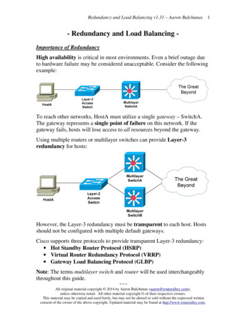
Part III – Special Topics of BridgesENCE717 – Bridge EngineeringSpecial Topics of Bridges II1. Strut-and-Tie Model (13.0)2. Stability (14.0)3. Redundancy Analysis (15.0)4. Integral Bridges (16.0)Chung C. Fu, Ph.D., P.E.(http: www.best.umd.edu)5. Bridge Geometry (18.0)6. Dynamic/Earthquake Analysis1Redundancy Analysis (Chapter 15) Redundancy is the quality of a bridge to perform asdesigned in a damaged state due to the presence ofmultiple load paths. Three types of redundancy, load-path, structural andinternal redundancies The non-redundant steel members are the fracturecritical members (FCM). Fracture critical members are those in axial tensionor tension components of bending members whosefailure would result in the failure of the structure.Redundancy AnalysisLoad Path Redundancy - A member is considered load pathredundant if an alternative and sufficient load path isdetermined to exist. Load path redundancy is the type ofredundancy that designers consider when they count parallelgirders or load paths. However, merely determining thatalternate load paths exist is not enough. The alternative loadpaths must have sufficient capacity to carry the loadredistributed to them from an adjacent failed member. If theadditional redistributed load fails the alternative load path,progressive failure occurs, and the members could in fact, befracture critical. In determining the sufficiency of alternativeload paths, all elements present (primary and secondarymembers) should be considered.
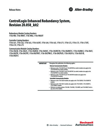
Redundancy AnalysisStructural redundancy - A member is considered structurallyredundant if its boundary conditions or supports are such thatfailure of the member merely changes the boundary or supportconditions but does not result in the collapse of thesuperstructure. Again, the member with modified supportconditions must be sufficient to carry loads in its newconfiguration. For example, the failure of the negative–momentregion of a two span continuous girder is not critical to thesurvival of the superstructure if the positive-moment region issufficient to carry the load as a simply supported girder.Internal Redundancy - A member is considered internallyredundant if alternative and sufficient load paths exist within themember itself such as the multiple plies of riveted steelmember.Redundancy AnalysisFCM by Caltrans: Tension ties in arch bridgesTension members in truss bridgesTension flanges and webs in two-girder bridgesTension flanges and webs in single or double box girder bridgesTension flanges and webs in floor beams/cross girdersTension braces in the cross frame of horizontally curved girderbridges Attachments welded to a FCM when their dimension exceeds 100mm (4 in.) in the direction parallel to the calculated tensile stress inthe FCM. Tension components of bent caps Splice plates of a FCMRedundancyAnalysis Figure 15.1 Flowchart foridentifying FCMs ofcomplex steel bridges(Caltran 2004)Redundancy AnalysisDesign AlternatesStructural ElementsAll Basic UncutDesignsMain Truss MembersGusset PlatesConnections&All Basic CutDesignsCross BeamsSupportsCode ChecksDead Load ConditionsLive Load MaximaTension AllowablesColumn CompressionFatigue (stress range)Non-FatigueSecondary StressesHalf-Truss StabilityRedundancyDeflections
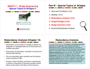
Redundancy AnalysisFigure 15.5 – Plasticsection definition offracture criticalmembers (FCMs)10786Redundancy Analysis119125413Figure 15.12 - Attack Scenario 1Response (Step 11)32161415Figure 15.11 ‐ Attack Scenario 1 (674 lbsTNT) Static Equivalent Joint Loads on a PCBeam BridgeFigure 15.4 - 3D Model in ANSYSRedundancy AnalysisFigure 15.16 - Attack Scenario 1Response (Step 10)Figure 15.15 ‐ Attack Scenario 1 (674 lbsTNT) Static Equivalent Joint Loads of aContinuous Steel Plate Girder BridgeRedundancy Analysis1. Member failure, load factor LF1 - Live load on the linearelastic model and then increasing the live load until the firstmember fails2. Ultimate limit state, load factor LFu – Live load on thenonlinear structural model and then increasing the live loaduntil the bridge collapses.3. Functionality limit state, factor LFf - Live load on thenonlinear structural model and then increasing the live loaduntil displacement in a main longitudinal member equal tothe span length/100.4. Damaged condition limit state, factor LFd – Live load on thenonlinear structural model of the damaged bridge and thenincreasing the live load until the bridge collapses.12
Redundancy AnalysisRedundancy AnalysisBridge Redundancy Indices: Ru the redundancy in the ultimate limit stateRu LFu/LF1 1.3 min reqd. Rf the redundancy in the functionality limit stateRf LFf/LF1 1.1 min reqd. Rd the redundancy in the damaged condition limitstate.Possible damaged form: Suspenders and ties tension yield (Findthe most efficient hunger W3) Arch instability under compression andmoment (arch rib springline and x 32.5m) The main beam subjected to bendingmoment (Hunger W3 & X 31.5m)116m arch spanRd LFd/LF1 0.5 min reqd.16.5m roadway131423.08m heightIntegral Bridges (Chapter 16)Redundancy AnalysisBridge Redundancy Indices: Ru the redundancy in the ultimate limit stateRu LFu/LF1 74/49 1.51 1.3 min. reqd. Rf the redundancy in the functionality limit stateRf LFf/LF1 64/49 1.3 1.1 min. reqd.Figure 16.3 – Integral abutment with flexible pilesFigure 16.1 – Integral pier on ramp FR‐A overSR6060, Pittsburgh, PA, USA Rd the redundancy in the damaged condition limit state.Middle hanger fails Rd LFd/LF1 54.86/49 1.12.Single tie failure Rd LFd/LF1 60/49 1.22Failure in anti-rotation in crown of arch Rd 51.03/49 1.04Failure in anti-rotation in springline of arch Rd 44.65/49 0.91min. Rd 0.91 0.5 min reqd15
Integral BridgesIntegral Bridges(1) Equivalent cantilever FE modelFigure 16.4 – Semi‐integral abutmentFigure 16.5 – Full integral abutmentIntegral Bridges(2) Soil-spring FE modelFigure 16.8 – The modified Ramberg‐Osgood curve for a typical p‐y curve(a) Actual system(b) Equivalent systemFigure 16.7 – Cantilever idealization of a fixed-headed pileIntegral Bridges(3) Soil continuum FE modelsoil-pile interaction where thesoil is idealized by three sets ofsprings: lateral springs, verticalsprings and a point spring.Soil spring and p-y curve - To allow the stiffness of the deck-girderconnection to be varied, spring tied elements are employed at theirinterface. Nonlinear spring elements model the soil backfill as well as thesoil around the piles.
Bridge Geometry (Chapter 18)Bridge Geometry Type of horizontal curves –– Tangents (straight lines)– Arc (constant curvature)– Spiral (a transition from one curvature to another thatthe curvature change is proportional to curvedistance) Type of vertical curves – Horizontal curves of a roadway centerline and span layout Girder axes follow roadway horizontal curvesFigure 18.1 – Roadway and girder horizontal curves– Parabolic curve (sag or crest vertical curve) Types of transverse curves– Parabolic curve Superelevation and superwideningBridge Geometry21Figure 18.2 – Girder axes follow roadway vertical curves, and curves in girder profilesBridge GeometryFigure 18.6 – Transverse curve and local coordinate systemFigure 18.4 – An example of a plane curve ‐ components of a compound curveSuperelevation caseFigure 18.5 – An example of a vertical curve – components of a vertical curveFigure 18.7 – An example of key cross sections
Bridge GeometryBridge GeometryPrecast Segment BridgeGeometry ControlSuperwidening caseFigure 18.8 – Plane view of a transverse curve transition exampleFigure 18.16 – Schematic views of short‐linecasting systemIn short-line casting system only onegirder segment is casted at one time on thecasting bed, and cured segments aremoved to storage yard.Figure 18.9 – Perspective view mainline and cross sectionsBridge GeometryFigure 18.17 – Adjustment of match segmentand form works for casting segment (courtesy ofNiniveTM CASSEFORME)Bridge GeometryFigure 18.19 – Segmentsassembled and global/localcoordinate systemsThe disadvantage of short-linesystem is the geometry controlduring the casting of eachsegment.Figure 18.20 – Local (casting yard) coordinate system andcontrol points for alignmentFigure 18.24 – Prediction of setup values for a match‐cast segment
5. Bridge Geometry (18.0) 6. Dynamic/Earthquake Analysis Redundancy Analysis (Chapter 15) Redundancy is the quality of a bridge to perform as designed in a damaged state due to the presence of multiple load paths. Three types of redundancy, load-path, structural and internal redund