Transcription
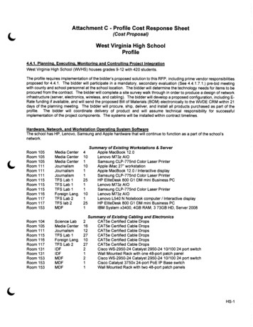
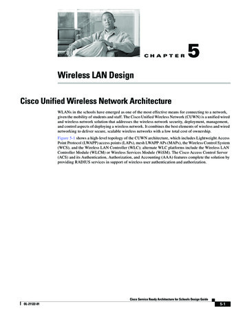
CH A P T E R5Wireless LAN DesignCisco Unified Wireless Network ArchitectureWLANs in the schools have emerged as one of the most effective means for connecting to a network,given the mobility of students and staff. The Cisco Unified Wireless Network (CUWN) is a unified wiredand wireless network solution that addresses the wireless network security, deployment, management,and control aspects of deploying a wireless network. It combines the best elements of wireless and wirednetworking to deliver secure, scalable wireless networks with a low total cost of ownership.Figure 5-1 shows a high-level topology of the CUWN architecture, which includes Lightweight AccessPoint Protocol (LWAPP) access points (LAPs), mesh LWAPP APs (MAPs), the Wireless Control System(WCS), and the Wireless LAN Controller (WLC); alternate WLC platforms include the Wireless LANController Module (WLCM) or Wireless Services Module (WiSM). The Cisco Access Control Server(ACS) and its Authentication, Authorization, and Accounting (AAA) features complete the solution byproviding RADIUS services in support of wireless user authentication and authorization.Cisco Service Ready Architecture for Schools Design GuideOL-21122-015-1
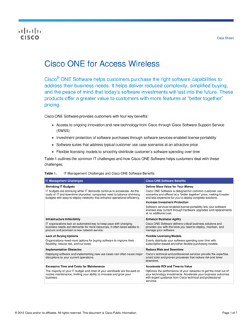
Chapter 5Wireless LAN DesignCisco Unified Wireless Network ArchitectureFigure 5-1Cisco Unified Wireless Network Architecture OverviewCisco Catalyst3750G IntegratedCisco WCSWireless LANNavigatorControllerBrowser BasedWCisco WirelessControl System(WCS)Cisco WirelessLAN ControllerModule (WLCM)CiscoWCSCiscoWCSCisco WirelessLAN ControllerNSECiscoMobileServicesEngineThird PartyIntegratedApplications:E911, AssetTracking, ERP,WorkflowAutomationCisco AironetWireless BridgeCisco Catalyst 6500Series WirelessServices Module(WiSM)Cisco AironetLightweightAccess Points(802.11a/b/gand 802.11n)Chokepoint125 kHzCiscoCompatibleClientDevicesCisco AironetWireless LANClient AdaptersCisco Aironet1500 SeriesLightweightOutdoor MeshAccess Points225263CiscoCompatibleWi-Fi TagsThe CUWN network is composed of two key elements: Wireless LAN Controllers (WLCs) and AccessPoints (APs). These form the core of the Wireless LAN system, where the APs provide the radioconnection between wireless clients and the network, and the WLCs provide network.Figure 5-2 illustrates one of the primary features of the architecture: how Lightweight Access PointProtocol (LWAPP) or Control and Provisioning of Wireless Access Points (CAPWAP) access points(LAPs) use the LWAPP/CAPWAP protocol to communicate with and tunnel traffic to a WLC.Cisco Service Ready Architecture for Schools Design Guide5-2OL-21122-01
Chapter 5Wireless LAN DesignCisco Unified Wireless Network ArchitectureNoteCUWN is migrating from the LWAPP protocol to CAPWAP, and the WLC software version in theSchools SRA uses CAPWAP. The fundamentals of the architecture and operation are the same.Documents discussing the LWAPP architecture operation and behavior are still valid for CAPWAP, apartfrom the UDP port numbers. For the purposes of this document and other documents referring to LWAPP,the Cisco CAPWAP implementation can be considered as a superset of LWAPP features and behavior.Figure 5-2LAP and WLC LWAPP/CAAPAPLW227453LWAPPAPPWAP/CLWAPP/CAPWAP has three primary functions: Control and management of the LAP Tunneling of WLAN client traffic to the WLC Collection of 802.11 data for the management of the Cisco Unified Wireless SystemLWAPP FeaturesThe easier a system is to deploy and manage, the easier it will be to manage the security associated withthat system. Early implementers of WLAN systems that used “fat” APs (autonomous or intelligent APs)found that the implementation and configuration of such APs was the equivalent of deploying andmanaging hundreds of individual firewalls, each requiring constant attention to ensure correct firmware,configuration, and safeguarding. Even worse, APs are often deployed in physically unsecured areaswhere theft of an AP could result in someone accessing its configuration to gain information to aid insome other form of malicious activity.LWAPP addresses deployment, configuration, and physical security issues by doing the following: Removing direct user interaction and management of the AP. Instead, the AP is managed by theWLC through its LWAPP connection. This moves the configuration and firmware functions to theWLC, which can be further centralized through the use of the WCS. Having the AP download its configuration from the WLC, and be automatically updated whenconfiguration changes occur on the WLC. Having the AP synchronize its firmware with its WLC, ensuring that the AP is always running thecorrect software version.Cisco Service Ready Architecture for Schools Design GuideOL-21122-015-3
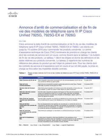
Chapter 5Wireless LAN DesignCisco Unified Wireless Network Architecture Storing sensitive configuration data at the WLC, and storing only IP address information on the AP.In this way, if the AP is physically compromised, there is no configuration information resident inNVRAM that can be used to perform further malicious activity. Mutually authenticating LAPs to WLCs, and AES encrypting the LWAPP control channel.In addition to the improvements in physical security, firmware, and configuration management offeredby LWAPP, the tunneling of WLAN traffic in an LWAPP-based architecture improves the ease ofdeployment without compromising the overall security of the solution. LAPs that support multipleWLAN VLANs can be deployed on access-layer switches without requiring dot1q trunking or addingadditional client subnets at the access switches. All WLAN client traffic is tunneled to centralizedlocations (where the WLC resides), making it simpler to implement enterprise-wide WLAN access andsecurity policies.Schools SRA ArchitectureFigure 5-3 shows a simple schematic of the CUWN integration into the schools SRA. The key featuresof the CUWN integration is the use of a WLC at each school, with the management function (WCS)located at the district office. If context-aware services are implemented, the Cisco Mobility ServicesEngine (MSE) may be placed at the school; for smaller schools, an MSE at the district office may providea centralized service.The standalone WLCs used in this design support AP capacities from 12 to 250 APs per WLC, andmultiple WLCs may be deployed at the same school if more than 250 APs are required or if a loadsharing or higher availability WLAN solution is required. An alternate higher availability solution is touse a WLC at the district office as a backup WLC for the school’s WLCs. This is known as an N 1solution, where a district office WLC maintains sufficient capacity to support the APs of any individualschool site.A similar principle to N 1 is used to provide high availability for the AAA service provided by the CiscoACS server. Each school will have a local ACS server to provide AAA services, and use the district officeACS server as its secondary AAA server.Cisco Service Ready Architecture for Schools Design Guide5-4OL-21122-01
Chapter 5Wireless LAN DesignManagementFigure 5-3High level view of the CUWN SRA IntegrationACSMSEWNSWCSEWLCMANDistrict OfficeACSWNSACSEMSEWLCWLCCisco Catalyst 4500 School227454Cisco Catalyst 3750 SchoolManagementEach of the WLCs has both a CLI and web interface to provide WLAN configuration and managementfeatures, but for a complete lifecycle management solution, the Cisco Wireless Control System (WCS)is needed. The WCS supports the delivery of high-performance applications and mission-criticalsolutions that simplify business operations and improve productivity. This comprehensive platformscales to meet the needs of small, midsize, and large-scale wireless LANs across local, remote, national,and international locations. The WCS gives IT managers immediate access to the tools they need, whenthey need them, to more efficiently implement and maintain new or expanding WLANs—all from acentralized location requiring minimal IT staffing. Operational costs are significantly reduced throughthe Cisco WCS’s intuitive GUI, simplified ease-of-use, and built-in tools that deliver improved ITCisco Service Ready Architecture for Schools Design GuideOL-21122-015-5
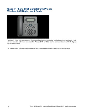
Chapter 5Wireless LAN DesignManagementefficiency, lowered IT training costs, and minimized IT staffing requirements, even as the networkgrows. Cisco WCS lowers operational costs by incorporating the full breadth of managementrequirements, from radio frequency, to controllers services, and into a single unified platform.The Cisco WCS scales to manage hundreds of Cisco wireless LAN controllers, which in turn can managethousands of Cisco Aironet access points including the next-generation Cisco Aironet 1140 and 1250Series 802.11n access points. For large-scale indoor and outdoor deployments, Cisco WCS Navigatorcan be included to simultaneously support up to 20 Cisco WCS platforms and 30,000 Cisco accesspoints. Adding mobility services such as context-aware software and adaptive wireless intrusionprevention systems (wIPS) is simplified through Cisco WCS integration with the Cisco MSE.Designing a wireless LAN that effectively supports business-critical data, voice, and video services issimplified with the Cisco WCS suite of built-in planning and design tools. Figure 5-4 shows an exampleof the simplified Wireless LAN Planning and Design Cisco WCS planning and design tools simplify theprocess of defining access point placement and determining access point coverage areas for standard andirregularly shaped buildings. These tools give IT administrators clear visibility into the radio frequency(RF) environment. They make it easier to visualize the ideal RF environment, anticipate future coverageneeds, and assess wireless LAN behavior. They help IT administrators reduce, and in many caseseliminate, improper RF designs and coverage problems that can lead to end-user troubletickets.Specialized Cisco WCS planning tools enable real-time assessment of the WLAN's readiness tosupport voice-over-WLAN (VoWLAN) and context-aware (location) services. VoWLAN servicessupport single and dual-mode Wi-Fi-enabled phones. Context-aware services use Cisco's patent pending“RF fingerprinting” technology to locate, track, and manage Wi-Fi-enabled devices and their contextualinformation in conjunction with Cisco MSE.Figure 5-4WCS planning toolsGetting the WLAN up and running quickly and cost-effectively to meet end-user needs is streamlinedwith the broad array of Cisco WCS integrated configuration templates. These easy-to-use templates anddeployment tools help IT managers provision and configure the wireless LAN to expressly deliver theservices that their business requires. Figure 5-5 shows an example of the Flexible Deployment Tools andConfiguration Templates available through an easy-to-use interface, make it simple to apply commonconfigurations across one or more wireless LAN controllers, regardless of their location in thenetwork—whether on the same LAN as Cisco WCS, on separate routed subnets, or across a wide-areaconnection. At the click of a button, IT administrators can streamline even the most complex controllerconfigurations, updates, and scheduling across the entire wireless network. Auto-provisioning accesspoints is just as simple, with easy-to-use templates that support customized configuration of single ormultiple access points.Cisco Service Ready Architecture for Schools Design Guide5-6OL-21122-01
Chapter 5Wireless LAN DesignManagementFigure 5-5WCS Deployment TemplatesCisco WCS is the ideal management platform for monitoring the entire WLAN to maintain robustperformance and deliver an optimal wireless experience to mobile end users. Cisco WCS centralizedinterface makes it easy to access information where it is needed, when it is needed, on demand or asscheduled. Figure 5-6 shows an example of the Customizable Dashboard and Easy-to-Use Web-BasedInterface Cisco WCS easy-to-use graphical displays serve as a starting point for maintenance, security,troubleshooting, and future capacity planning activities. Quick access to actionable data about healthyand unhealthy events occurring on the network is available from a variety of entry points, making CiscoWCS vital to ongoing network operations.The ever-present alarm summary in the Cisco WCS simplifiesaccess to critical information, faults, and alarms based on their severity. Detecting, locating, andcontaining unauthorized (rogue) devices is fully supported when location services are enabled.Figure 5-7 shows an example of the Ever-Present Alarm Summary and Simplified Rogue DeviceDetection and Location.Figure 5-6WCS Monitoring DashboardCisco Service Ready Architecture for Schools Design GuideOL-21122-015-7
Chapter 5Wireless LAN DesignManagementFigure 5-7WCS Alarm PanelsThe integrated workflow and expansive array of troubleshooting tools in the Cisco WCS help ITadministrators quickly identify, isolate, and resolve problems across all components of the Cisco UnifiedWireless Network. Cisco WCS supports rapid troubleshooting of any size WLAN with minimal ITstaffing. Figure 5-8 shows an example of the Integrated Workflows and Troubleshooting Tools. CiscoWCS makes it easy to quickly assess service disruptions, receive notices about performance degradation,research resolutions, and take action to remedy nonoptimal situations. Integrated workflows supportseamless linkage between all tools, alarms, alerts, searches, and reports for all infrastructure componentsand client devices.A variety of tools work together to help IT administrators understand the operationalnuances occurring on the WLAN and discover nonoptimal events occurring outside baseline parameterssuch as client connection or roaming problems. The ever-present search tool in Cisco WCS facilitatescross-network access to real-time and historic information about devices and assets located anywhere inthe wireless network. A built-in client troubleshooting tool provides a step-by-step method to analyzeproblems for all client devices. Cisco CleanAirsupports finding, classifying, and correlating sources ofinterference from Wi-Fi and non-Wi-Fi sources such as Bluetooth devices and cordless phones.Figure 5-8WCS Troubleshooting ToolsCisco Service Ready Architecture for Schools Design Guide5-8OL-21122-01
Chapter 5Wireless LAN DesignManagementCisco WCS includes customizable reporting that assists IT teams in more effectively managing,maintaining, and evolving the wireless LAN to meet ongoing business and operations requirements.Flexible reports provide access to the right data, at the right time, in a format to meet any requirement.Figure 5-9 shows an example of the Customizable Reports Meet Any Requirement. An extensive varietyof reports is available to help IT managers stay on top of network trends, maintain network control, auditoperations, and quickly address changing business and end-user requirements. Reports are customizablebased on user-defined parameters. Detailed analysis of what is going on, where and when in the network,as well as capacity planning, is simplified by collecting data from several reports and analyzing trendsto understand how the WLAN has changed over time. Understanding WLAN trends makes it easier toplan for future enhancements and growth.Figure 5-9WCS Customizable ReportsConnection to the Schools SRA NetworkFigure 5-10 and Figure 5-11 show the school switch to WLC physical connection in more detail, a keyfeature in of the WLC interface is its direct connection to the core distribution switch via a port channelinterface. This uses multiple Gigabit Ethernet connections from the WLC to the core/distribution switch.These Gigabit Ethernet connections are to different line cards on switches or line card to ensure that asingle switch or line card failure does not result in the loss of the WLC connection to the school network.The switch feature to achieve this is the same switch feature used for the Ether Channel connectionsbetween switches in the Schools SRA. The WLC feature is called link aggregation (LAG). LAG isdisabled by default on the WLC and requires a WLC reboot to be enabled. This allows the WLC to usethe same port channel configuration as the access switches when connecting to the core/distributionswitch.Cisco Service Ready Architecture for Schools Design GuideOL-21122-015-9
Chapter 5Wireless LAN DesignManagementFigure 5-104500 School Switch WLC Physical ConnectionACSWNSEMSE227461WLCFigure 5-11750 School Switch WLC Physical ConnectionACS227462WLCThe WLC connects to the switch via a 802.1Q trunk connection, as shown in Figure 5-12, and multipleSVIs need to be configured on the switch to support the CUWN implementation. The key SVIs are anSVI for the management and AP manager interface of the WLC, and the SVIs for each of the differentWLANs implemented on the WLC; there is not always a one-to-one relationship between SVIs andWLANs, but in most simple WLAN deployments this is the case.Switch WLC Layer-2 ConnectionTrunk227463Figure 5-12Figure 5-13 shows an example of the interface configuration summary on school WLC. The keyinterfaces of interest are ap-manger, manager, and wlan data1, wlan data2, and wlan voice1 interfaces.Cisco Service Ready Architecture for Schools Design Guide5-10OL-21122-01
Chapter 5Wireless LAN DesignManagementThe server port is an out-of-band management interface not used in this design guide. The virtualinterface and its interface address are used to assist in the provisioning of seamless mobility. The virtualinterface is assigned an address during the initial configuration of the WLC and this address is typically1.1.1.1 for all controllers.Figure 5-13WLC Interface ExampleFigure 5-14 shows the mapping of a particular WLAN SSID to a defined interface. A WLAN can bemapped to the management interface (this is normally not recommended), or any dynamic interface.Figure 5-14WLAN ExampleCisco Service Ready Architecture for Schools Design GuideOL-21122-015-11
Chapter 5Wireless LAN DesignManagementRF Groups and Mobility GroupsPart of a WLCs role is to manage the RF network in its area, and to provide mobility services to WLCsin its network. To define the area of the RF network that you are interested in managing, use an RF groupname; to define the mobility services domain, use a mobility group. The details of RF groups andmobility groups are beyond the scope of this design guide, but the key point for the design is that the RFnetwork area and the mobility services domain will typically be a single school campus, and only WLCsthat are at the same school should have the same RF group name or mobility group name. Figure 5-15shows an example of the RF and mobility group configuration on the controllers. Each school campuscan be given a different RF group and mobility group as the WLCs are different schools and are notexpected to be in the same RF group or mobility group.Figure 5-15Mobility Groups and RF Groups ExampleA school with only one WLC will have a mobility group with only its own details in the mobility group.If there is more than one WLC at the school, then the mobility group configuration will contain bothWLCs.Figure 5-16 shows the single WLAN example and Figure 5-17 shows a multiple WLC example. If thereis only one WLC, the mobility group information is automatically populated. Additional WLCs musthave the MAC address and management IP address added manually.Cisco Service Ready Architecture for Schools Design Guide5-12OL-21122-01
Chapter 5Wireless LAN DesignManagementFigure 5-16Mobility Groups for a Single WLCFigure 5-17Mobility Groups for a Multiple WLCsExample WLAN ConfigurationsIn a typical school WLAN environment, it is expected that there be multiple WLANs (SSIDs) servingdifferent purposes and different client groups. This section addresses the examples of what would beconsidered typical WLAN examples. A secured data WLAN network that uses 802.1X/EAP to provide AAA functionality anddynamically generated per-user, per-session encryption key. A secured VoWLAN network that also uses 802.1X/EAP to provide AAA functionality andoptimized for voice.Cisco Service Ready Architecture for Schools Design GuideOL-21122-015-13
Chapter 5Wireless LAN DesignManagement An open unencrypted WLAN for access to a WLAN network for unmanaged clients such as studentlaptops, iPod, and iPhones.For ease of administration and support for users who visit multiple schools, the WLAN SSIDs should bethe same for each school in the district. In addition, the SSIDs should be broadcast and have meaningfulnames.Secured Staff WLANFigure 5-18 shows the general WLAN configuration tab for the secured data WLAN network. The keypoint shown are the security policy that has been set under the security tab and the WLC interface thatthe WLAN has been mapped to. The security configuration recommended is to use WPA2 with802.1X CCKM. Most WLAN should now support WPA2, and CCKM has been added to 802.1X as itprovides a faster roaming for WLAN clients. This is for clients that support CCKM, while using theAAA features of 802.1X/AP to secure the WLAN connection.Figure 5-18General Configuration for Secured WLANFigure 5-19 shows the QoS configuration for the secured data WLAN; in this case, the QoS profile is setto Silver, which is best effort setting. The WMM policy is set to disabled, as disabled WMM is theequivalent of best effort. The primary role of WMM is to give higher priority to voice and video trafficover the WLAN. Unless the school is planning to deliver interactive voice and video applications to theirWLAN data clients, WMM can remain disabled.Note802.11n standard requires WMM be enabled and, therefore, WMM must be enabled on all WLANs inthe 802.11n deployments. In this case, the WMM policy would be set to allowed.Cisco Service Ready Architecture for Schools Design Guide5-14OL-21122-01
Chapter 5Wireless LAN DesignManagementFigure 5-19Secured Staff WLAN QoSFigure 5-20 shows the secured data WLAN advanced configuration. The only change from the defaultsettings on the tab is enabling the DHCP address assignment required feature. Typically, WLAN mobileclients use DHCP, and any statically configured client runs the risk of introducing an address duplicationissue.Figure 5-20Secured Staff Advanced ConfigurationSecured VoWLANFigure 5-21 shows the General Tab of the voice over WLAN (VoWLAN). The primary differencebetween this WLAN and the secured data WLAN is that the security policy is WPA with CCKM, becausethis is the optimum security configuration for the Cisco 7921G and 7925G. The other difference is thatthe radio policy has been set for 802.11a only.The use of 802.11a for the VoWLAN will depend on a number of factors, but the Cisco 7921G and7925G are dual-band phones, and can use both bands but do not roam between bands. This means thatonce the handset associates with a network in one band, it will not leave that band while call quality ismaintained. Keeping the VoWLAN handsets in the 802.11a band will ensure that the 2.4GHz bandremains available for other client devices. Whether this is a viable option for a school depends on therequired call capacity of the school’s WLAN and the type of AP network that has been deployed.Cisco Service Ready Architecture for Schools Design GuideOL-21122-015-15
Chapter 5Wireless LAN DesignManagementFigure 5-21VoWLAN General ConfigurationFigure 5-22 shows the QoS Tab for the VoWLAN. In this WLAN configuration, WMM is required (boththe 7921G and 7921G) support WMM, and WMM will give voice traffic priority over other WLANtraffic on the network. The QoS profile is set to Platinum to ensure that the QoS classification isappropriate for voice. The QoS profile controls the maximum classification value for both the WLANframes and LWAPP packets.Figure 5-22VoWLAN QoS ConfigurationThe Advanced Tab for the VoWLAN is the secured data WLAN. There is an option for VoIP snoopingand reporting, but this option pertains only to a particular type of SIP and is not applicable to the CIsco7921G and 7925G handsets.To protect VoIP call quality, the WLC can perform call admission control (CAC) to prevent VoWLANcalls being added to an access point that cannot take any additional VoWLAN calls withoutcompromising call quality. An example of the CAC configuration page is shown in Figure 5-23.NoteThere is a separate CAC page for each RF band.Cisco Service Ready Architecture for Schools Design Guide5-16OL-21122-01
Chapter 5Wireless LAN DesignManagementFigure 5-23VoWLAN Call Admission ControlThe CUWN prioritizes traffic based upon the QoS profiles applied to each WLAN, but it does not changethe IP QoS classification (DSCP) of the client traffic carried by the CUWN. This means that client trafficthat leaves the CUWN may need to be reclassified based upon the network policy. There are two waysof achieving this.1.Applying policy at each of the network SVIs that connect the WLC to the network.2.Learning the QoS policy that was applied within the CUWN as this should be in alignment with thenetwork policy.The second method is preferable as it requires less configuration and maintenance of the policy; thepolicy only needs to be maintained upon WLCs, and not open the WLCs and the connected switch. Toachieve this, the Wired Protocol in the QoS profiles (Platinum, Gold, Sliver, and Bronze) must be set to802.1p and all other settings may remain as default. This configures the WLC to set the 802.1p markingof the frames sent from the WLC to reflect QoS policy on that WLAN. For example, the IP packet wasfrom a Platinum WLAN and had a DSCP value of EF, the WLC would use a CoS value of 5 in the frameheader. If the same packet had been on a Silver WLAN, the CoS value would be 0. Therefore, if the WLCis connected to switch network that is configured to trust CoS and maintains a translation table betweenCoS and DSCP for its network, the translation between CUWN policy and network policy will occurautomatically. See Figure 5-24.For a further information on WLAN QoS, refer to the Voice over WLAN Design Guide at the ok.htmlCisco Service Ready Architecture for Schools Design GuideOL-21122-015-17
Chapter 5Wireless LAN DesignManagementFigure 5-24Controller QoS ProfilesWeb Authenticated Student AccessIn many situations, it is not possible to administer and support the WLANs clients that are required toconnect to the network. There can be a wide variety of operating systems, WLAN clients, and user abilityto support, and a very limited amount of support resources. In cases like this, a typical solution is tocreate an open WLAN that does not perform 802.1X/EAP authentication of encryption. This is normallysimple enough for all users and all platforms.To provide some level of access control and audit trail, these WLANs perform a Web-Authenticationwhere all network access—apart from DHCP and DNS—is blocked until the user enters a correctusername and password into an authentication web page. This authentication web page will be forced tothe WLAN client screen when the client attempts to open any web page. Additional security policy maybe applied through filters on the WLC, upstream switch and/or firewall. See Figure 5-25.Figure 5-25Student Open WLAN GeneralCisco Service Ready Architecture for Schools Design Guide5-18OL-21122-01
Chapter 5Wireless LAN DesignManagementFigure 5-26 shows the QoS settings for the Student WLAN WMM is disabled, and the QoS profile ofBronze. WMM is disabled to prevent WLAN clients on the Student assigning a WMM classification, andthe QoS profile of Bronze assigns network priority of less than best effort.Note802.11n standard requires WMM be enabled and, therefore, WMM must be enabled for all WLANs in a802.11n deployments. In this case, the WMM policy would be set to allowed.Figure 5-26Student WLAN QoSFigure 5-27 shows the security configuration for the student WLAN. Web policy presents a number ofweb-based controls for network access, the option chosen in the case is authentication. Authenticationrequires the client to enter username and password through a web page. The web page used can be aninternal server provided by the WLC, or to a third-party service.Figure 5-27Student WLAN SecurityFigure 5-28 shows an example of the internal web page option for web authentication, this allows thecreation of a simple web page as shown in Figure 5-29.The usernames and passwords for authentication can use the Local Net Users database on the WLC or aRADIUS AAA server. The authentication mechanism between the WLC and the RADIUS is PAP.Cisco Service Ready Architecture for Schools Design GuideOL-21122-015-19
Chapter 5Wireless LAN DesignManagementNoteFigure 5-28Web Authentication ConfigurationFigure 5-29Web Authentication Example ScreenThis web authentication mechanism can also be used with the WLC is used to provide wired guestaccess.AP Deployments ConsiderationsAs with any other WLAN deployment, the key design decision are as follows: which areas requirecoverage and what level of performance is required in those areas with WLAN coverage. The Schoolsenvironment introduces an additional challenge to the design considerations due to the structured natureof network use. That is, classes start at particular times and a teacher will often ask the entire class tostart an activity at the same time. This is a contrast to a typical enterprise deployment where networkCisco Service Ready Architecture for Schools Design Guide5-20OL-21122-01
Chapter 5Wireless LAN DesignManagementusers are much more independent. The structured nature of a school network usage can greatly increasethe peaks in load upon the WLAN network. The general guidance for enterprise AP deployments hasbeen 15 to 20 active clients per AP, but the peaks in demand at schools has seen this translate into twoAPs per class room, where there may be 20 to 30 students in that class room
Figure 5-1 Cisco Unified Wireless Network Architecture Overview The CUWN network is composed of two key elem ents: Wireless LAN Controllers (WLCs) and Access Points (APs). These form the core of the Wireless LAN system, where the APs provide the radio connection between wireless