Transcription
Multichassis LACPFirst Published: December 11, 2009Last Updated: February 8, 2011In Carrier Ethernet networks, various redundancy mechanisms provide resilient interconnection of nodesand networks. The choice of redundancy mechanisms depends on various factors such as transporttechnology, topology, single node versus entire network multihoming, capability of devices, autonomoussystem (AS) boundaries or service provider operations model, and service provider preferences.Carrier Ethernet network high-availability can be achieved by employing both intra- and interchassisredundancy mechanisms. Cisco’s Multichassis EtherChannel (MCEC) solution addresses the need forinterchassis redundancy mechanisms, where a carrier wants to “dual home” a device to two upstreampoints of attachment (PoAs) for redundancy. Some carriers either cannot or will not run loop preventioncontrol protocols in their access networks, making an alternative redundancy scheme necessary. MCECaddresses this issue with enhancements to the 802.3ad Link Aggregation Control Protocol (LACP)implementation. These enhancements are provided in the Multichassis LACP (mLACP) featuredescribed in this document.Finding Feature InformationYour software release may not support all the features documented in this module. For the latest featureinformation and caveats, see the release notes for your platform and software release. To find informationabout the features documented in this module, and to see a list of the releases in which each feature issupported, see the “Feature Information for mLACP” section on page 57.Use Cisco Feature Navigator to find information about platform support and Cisco software imagesupport. To access Cisco Feature Navigator, go to http://www.cisco.com/go/cfn. An account onCisco.com is not required.Contents Prerequisites for mLACP, page 2 Restrictions for mLACP, page 2 Information About mLACP, page 3Americas Headquarters:Cisco Systems, Inc., 170 West Tasman Drive, San Jose, CA 95134-1706 USA
Multichassis LACPPrerequisites for mLACP How to Configure mLACP, page 17 Configuration Examples for mLACP, page 37 Additional References, page 55 Feature Information for mLACP, page 57 Glossary, page 58Prerequisites for mLACP The command lacp max-bundle must be used on all PoAs in order to operate in PoA control andshared control modes.– The maximum number of links configured cannot be less than the total number of interfaces inthe link aggregation group (LAG) that is connected to the PoA.– Each PoA may be connected to a dual-homed device (DHD) with a different number of linksfor the LAG (configured with a different number of maximum links). Each PoA must be configured using the port-channel min-link command with the desiredminimum number of links to maintain the LAG in the active state. Each PoA must be configured with the errdisable recovery cause mlacp command if brute-forcefailover is being used. For DHD control there must be an equal number of links going to each PoA. The max-bundle value must equal the number of links connected locally to the PoA (no localintra-PoA active or standby protection). LACP fast switchover must be configured on all devices to speed convergence.Restrictions for mLACP2 mLACP does not support Fast Ethernet. mLACP does not support half-duplex links. mLACP does not support multiple neighbors. Converting a port channel to mLACP can cause a service disruption. The maximum number of member links per LAG per PoA is restricted by the maximum number ofports per port channel, as limited by the platform. System priority on a DHD must be a lesser priority than on PoAs. MAC Tunneling Protocol (MTP) supports only one member link in a port channel. A port-channel or its member links may flap while LACP stabilizes. DHD-based control does not function when min-links is not configured. DHD-controlled revertive behavior with min-links is not supported. Brute-force failover always causes min-link failures. Any failure with brute-force failover behaves revertively.
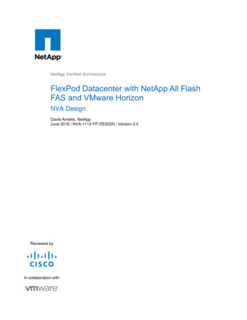
Multichassis LACPInformation About mLACPInformation About mLACP Overview of Multichassis EtherChannel, page 3 Interactions with the MPLS Pseudowire Redundancy Mechanism, page 4 Redundancy Mechanism Processes, page 5 Dual-Homed Topology Using mLACP, page 6 Failure Protection Scenarios, page 9 Operational Variants, page 10 mLACP Failover, page 11Overview of Multichassis EtherChannelIn Multichassis EtherChannel (MCEC), the DHD is dual-homed to two upstream PoAs. The DHD isincapable of running any loop prevention control protocol such as Multiple Spanning Tree (MST).Therefore, another mechanism is required to prevent forwarding loops over the redundant setup. Onemethod is to place the DHD’s uplinks in a LAG, commonly referred to as EtherChannel. This methodassumes that the DHD is capable of running only IEEE 802.3ad LACP for establishing and maintainingthe LAG.LACP, as defined in IEEE 802.3ad, is a link-level control protocol that allows the dynamic negotiationand establishment of LAGs. An extension of the LACP implementation to PoAs is required to convey toa DHD that it is connected to a single virtual LACP peer and not to two disjointed devices. This extensionis called Multichassis LACP or mLACP. Figure 1 shows this setup.Figure 1MCEC with mLACPVirtualLACP PeerStandbyPoADHDEtherChannelwith mLACPActivePoA277477Inter-chassisCommunicationThe PoAs forming a virtual LACP peer, from the perspective of the DHD, are defined as members of aredundancy group. For the PoAs in a redundancy group to appear as a single device to the DHD, thestates between them must be synchronized through the Interchassis Communication Protocol (ICCP),which provides a control-only interchassis communication channel (ICC).3
Multichassis LACPInformation About mLACPIn Cisco IOS Release 12.2(33)SRE, the system functions in active/standby redundancy mode. In thismode DHD uplinks that connect to only a single PoA can be active at any time. The DHD recognizesone PoA as active and the other as standby but does not preclude a given PoA from being active for oneDHD and standby for another. This capability allows two PoAs to perform load sharing for differentservices.Interactions with the MPLS Pseudowire Redundancy MechanismThe network setup shown in Figure 1 can be used to provide provider edge (PE) node redundancy forVirtual Private LAN Service (VPLS) and Virtual Private Wire Service (VPWS) deployments overMultiprotocol Label Switching (MPLS). In these deployments, the uplinks of the PoAs host the MPLSpseudowires that provide redundant connectivity over the core to remote PE nodes. Proper operation ofthe network requires interaction between the redundancy mechanisms employed on the attachmentcircuits (for example, mLACP) and those employed on the MPLS pseudowires. This interaction ensuresthe state (active or standby) is synchronized between the attachment circuits and pseudowires for a givenPoA.RFC 4447 introduced a mechanism to signal pseudowire status via the Link Distribution Protocol (LDP)and defined a set of status codes to report attachment circuit as well as pseudowire fault information.The Preferential Forwarding Status bit (draft-ietf-pwe3-redundancy-bit) definition proposes to extendthese codes to include two bits for pseudowire redundancy applications: Preferential forwarding status: active or standby Request pseudowire switchoverThe draft also proposes two modes of operation: Independent mode—The local PE decides on its pseudowire status independent of the remote PE. Primary and secondary modes—One of the PEs determines the state of the remote side through ahandshake mechanism.For the mLACP feature, operation is based on the independent mode. By running ICC between the PoAs,only the preferential forwarding status bit is required; the request pseudowire switchover bit is not used.The local pseudowire status (active or standby) is determined independently by the PoAs in a redundancygroup and then relayed to the remote PEs in the form of a notification. Similarly, the remote PEs performtheir own selection of their pseudowire status and notify the PoAs on the other side of the core.After this exchange of local states, the pseudowires used for traffic forwarding are those selected to beactive independently on both local and remote ends.The attachment circuit redundancy mechanism determines and controls the pseudowire redundancymechanism. mLACP determines the status of the attachment circuit on a given PoA according to theconfigured LACP system and port priorities, and then the status of the pseudowires on a given PoA issynchronized with that of the local attachment circuits. This synchronization guarantees that the PoAwith the active attachment circuits has its pseudowires active. Similarly, the PoA with the standbyattachment circuits has its pseudowires in standby mode. By ensuring that the forwarding status of theattachment circuits is synchronized with that of the pseudowires, the need to forward data between PoAnodes within a redundancy group can be avoided. This synchronization saves platform bandwidth thatwould otherwise be wasted on inter-PoA data forwarding in case of failures.4
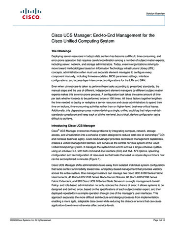
Multichassis LACPInformation About mLACPRedundancy Mechanism ProcessesThe Carrier Ethernet redundancy solution should include the following processes (and how they applyto the mLACP solution): Attachment circuit active or standby status selection—This selection can be performed by the accessnode or network, the aggregation node, or combination of the two. For mLACP, the attachmentcircuit status selection is determined through collaboration between the DHD and the PoAs. Pseudowire forwarding status notification—This notification is mandatory for mLACP operation inVPWS and VPLS deployments; that is, when the PoA uplinks employ pseudowire technology. Whenthe PoAs decide on either an active or standby role, they need to signal the status of the associatedpseudowires to the PEs on the far end of the network. For MPLS pseudowires, this is done usingLDP. MAC flushing indication—This indication is mandatory for any redundancy mechanism in order tospeed convergence time and eliminate potential traffic blackholing. The mLACP redundancymechanism should be integrated with relevant 802.1Q/802.1ad/802.1ah MAC flushing mechanismsas well as MAC flushing mechanisms for VPLS.Note Blackholing occurs when incoming traffic is dropped without informing the source that the datadid not reach its intended recipient. A black hole can be detected only when lost traffic ismonitored.Active VLAN notification—For mLACP, this notification is not required as long as the PoAs followthe active/standby redundancy model.Figure 2 shows redundancy mechanisms in Carrier Ethernet networks.5
Multichassis LACPInformation About mLACPFigure 2mLACPDSLAMDual-homingDSLAMRedundancy Mechanisms in Carrier Ethernet NetworksNative EthernetAccess (Hub & Spoke)Large-scaleEthernetAggregationMPLS CoreDSLAMMPLS Access/AggregationCE2-way VPLSRedundancy(VPLS PENodeRedundancy)EthernetAccess RingAccess RingDual-homingREPCE2-wayEoMPLS PWRedundancy(uPE & nPENodeRedundancy)uPECEDual-homing7478nPEAccess NetworkDual-homingL2GPDual-Homed Topology Using mLACPThe mLACP feature allows the LACP state machine and protocol to operate in a dual-homed topology.The mLACP feature decouples the existing LACP implementation from the multichassis specificrequirements, allowing LACP to maintain its adherence to the IEEE 802.3ad standard. The mLACPfeature exposes a single virtual instance of IEEE 802.3ad to the DHD for each redundancy group. Thevirtual LACP instance interoperates with the DHD according to the IEEE 802.3ad standard to formLAGs spanning two or more chassis.LACP and 802.3ad Parameter ExchangeIn IEEE 802.3ad, the concatenation of the LACP system MAC address and system priority form anLACP system ID (8 bytes). The system ID is formed by taking the two-byte system priority value as themost significant two octets of the system ID. The system MAC address makes up the remainder of thesystem ID (octets 3 to 8). System ID priority comparisons are based on the lower numerically valued ID.To provide the highest LACP priority, the mLACP module communicates the system MAC address andpriority values for the given redundancy group to its redundancy group peer(s) and vice versa. ThemLACP then chooses the lowest system ID value among the PoAs in the given redundancy group to useas the system ID of the virtual LACP instance of the redundancy group.Cisco IOS Release 12.2(33)SRE introduces two LACP configuration commands to specify the systemMAC address and system priority used for a given redundancy group: mlacp system-mac mac-addressand mlacp system-priority priority-value. These commands provide better settings to determine whichside of the attachment circuit will control the selection logic of the LAG. The default value for the systemMAC address is the chassis backplane default MAC address. The default value for the priority is 32768.6
Multichassis LACPInformation About mLACPPort IdentifierIEEE 802.3ad uses a 4-byte port identifier to uniquely identify a port within a system. The port identifieris the concatenation of the port priority and port number (unique per system) and identifies each port inthe system. Numerical comparisons between port IDs are performed by unsigned integer comparisonswhere the 2-byte Port Priority field is placed in the most significant two octets of the port ID. The 2-byteport number makes up the third and fourth octets. The mLACP feature coordinates the port IDs for agiven redundancy group to ensure uniqueness.Port NumberA port number serves as a unique identifier for a port within a device. The LACP port number for a portis equal to the port’s ifIndex value (or is based on the slot and subslot identifiers on the Cisco 7600router).LACP relies on port numbers to detect rewiring. For multichassis operation, you must enter the mlacpnode-id node-id command to coordinate port numbers be
The Preferential Forwarding Status bit (draft-ietf-pwe3-redundancy-bit) definition proposes to extend these codes to include two bits for pseudowire redundancy applications: † Preferential forwarding status: active or standby † Request pseudowire switchover The draft also proposes two modes of operation: