Transcription
Installing, Operating & MaintainingMUNCHKIN HIGH EFFICIENCY399M COMMERCIAL BOILERWARNINGIf the information in this manual is not followed exactly, a fire or explosion mayresult causing property damage, personal injury or loss of life.Do not store or use gasoline or other flammable vapors andliquids in the vicinity of this or any other appliance.WHAT TO DO IF YOU SMELL GAS Do not try to light any appliance. Do not touch any electrical switch: do not use any phone inyour building. Immediately call your gas supplier from a neighbor's phone.Follow the gas supplier's instructions. If you cannot reach your gas supplier, call the fire department.Installation and service must be performed by a qualifiedinstaller, service agency or the gas supplier.MH27745WARNINGThis manual must only be used by a qualified heating installer / servicetechnician. Failure to comply could result in severe personal injury, death orsubstantial property damage. It is also important to keep these Instructionswith the appliance.HEAT TRANSFER PRODUCTS, INC.120 BRALEY RD., E. FREETOWN, MA02717
USING THIS MANUALUSING THIS MANUALSPECIAL ATTENTION BOXESThroughout this manual you will see thesespecial attention boxes similar to this one,which are intended to supplement theinstructions and make special notice ofpotential hazards. These categories mean, inthe judgement of Heat Transfer Products, Inc.:DANGERDANGER indicates an imminently hazardoussituation which, if not avoided, will result indeath or serious injury.WARNINGWARNING indicates a potentially hazardoussituation which, if not avoided, could result indeath or serious injury.CAUTIONCAUTION Indicates a potentially hazardoussitutation which, if not avoided, may result inminor or moderate injury.CAUTIONCAUTION used without the safety alert symbolindicates a potentially hazardous situation which,if not avoided, may result in property damage.WARNINGS THIS UNIT IS FOR CATEGORY IV VENTING - 2 PIPE ONLY. THIS IS A SEALEDCOMBUSTION APPLIANCE. THIS HEATER INSTALLATION MUST CONFORM TO THE LATEST EDITION OF THE“NATIONAL FUEL GAS CODE” ANSI Z223.1 NFPA 54 AND OR CAN/CGA B149INSTALLATION CODES. STATE AND LOCAL CODES MIGHT ALSO APPLY TOINSTALLATION. WHERE REQUIRED BY THE AUTHORITY HAVING JURISDICTION, THEINSTALLATION MUST CONFORM TO THE STANDARDS FOR CONTROLS ANDSAFETY DEVICES FOR AUTOMATICALLY FIRED HEATERS, ANSI/ASME HEATERAND PRESSURE VESSEL CODE, Section IV, ALONG WITH CSD1. THE HEATER, GAS PIPING, WATER PIPING, VENTING AND ELECTRICAL MUST BEINSTALLED BY TRAINED & QUALIFIED PERSONNEL FAMILIAR WITHINSTALLATION PRACTICES, LOCAL CODE, LICENSING REQUIREMENTS. IF THE INFORMATION IN THESE INSTRUCTIONS ARE NOT FOLLOWED EXACTLY,A FIRE OR EXPLOSION MAY RESULT; CAUSING PROPERTY DAMAGE, PERSONALINJURY, OR DEATH. DO NOT STORE OR USE GASOLINE OR OTHER FLAMMABLE VAPORS ANDLIQUIDS IN THE VICINITY OF THIS OR ANY OTHER APPLIANCE; THE USE OF A LOW WATER CUT-OFF DEVICE MAY BE REQUIRED BY STATE ORLOCAL CODES IF THE MUNCHKIN IS INSTALLED ABOVE RADIATION LEVELS.2
TABLE OF CONTENTSTABLE OF CONTENTSPART 1 . . . . . . . . . . . . . . . . . . . . . .4 thru 6PART 6 . . . . . . . . . . . . . . . . . . . .29 thru 32GENERAL INFORMATIONSTART UP PROCEDURESABCDHow It Operates . . . . . . . . . . . . . . . . . .4Munchkin Ratings and Dimensions .4–5Pre-installation Requirements . . . . . . .5Pressure Relief Valve . . . . . . . . . . . . . .6ABCDPART 2 . . . . . . . . . . . . . . . . . . . . . .6 thru 8ELECTRICALAElectrical Connection . . . . . . . . . . . . . .6EFGItems to be checked beforelighting the Munchkin . . . . . . . . . . . . .29Lighting Instructions . . . . . . . . . . . . . .29Operating Instructions . . . . . . . . . . . .30Adjusting the Temperatureon the Munchkin Display . . . . . . . . . .30Status Menu . . . . . . . . . . . . . . . . . . . .31Test Mode . . . . . . . . . . . . . . . . . . . . . .31To Turn Off Gas to Appliance . . . . . . .31PART 3 . . . . . . . . . . . . . . . . . . . . .8 thru 10PART 7 . . . . . . . . . . . . . . . . . . . .32 thru 36GAS CONNECTIONSERVICINGABCGas Connection . . . . . . . . . . . . . . . . . . .9Gas Piping . . . . . . . . . . . . . . . . . . . . . . .9Gas Table . . . . . . . . . . . . . . . . . . . . . . . .9ABCPART 4 . . . . . . . . . . . . . . . . . . . .11 thru 17VENTINGABCDEFGGeneral . . . . . . . . . . . . . . . . . . . . . . . .11Approved Materials for ExhaustVent and Intake Air Pipe . . . . . . . . . . .11Exhaust/Vent / Air Intake PipeLocation . . . . . . . . . . . . . . . . . . . . . . . .11Exhaust Vent and Intake Air PipeSizing . . . . . . . . . . . . . . . . . . . . . . . . . .13Exhaust Vent and Air Intake PipeInstallation . . . . . . . . . . . . . . . . . . . . . .13Heater Removal from a Common VentSystem . . . . . . . . . . . . . . . . . . . . . . . .14Condensate Requirements . . . . . . . . .17Sequence of operation . . . . . . . . . . . .32Munchkin TemporaryFault Condition . . . . . . . . . . . . . . . . . .32Munchkin Fault RequiringManual Reset . . . . . . . . . . . . . . . . . . .34PART 8 . . . . . . . . . . . . . . . . . . . .37 thru 41MAINTENANCEABCDEMaintenance Procedures . . . . . . . . . .37Before Each Heating Season . . . . . . .37Condensate Cleaning Instructions . . .37Combustion ChamberCoil Cleaning Instructions . . . . . . . . . .38Munchkin Controller . . . . . . . . . . . . . .39PART 5 . . . . . . . . . . . . . . . . . . . .17 thru 28PIPINGABCDHydronic piping withCirculators or Zone Valves . . . . . . . . .17Circulator Sizing . . . . . . . . . . . . . . . . .18Fill and Purge Heating System . . . . . .19Piping Illustrations . . . . . . . . . . . . .20–283
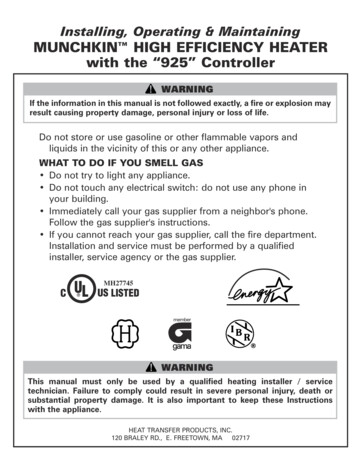
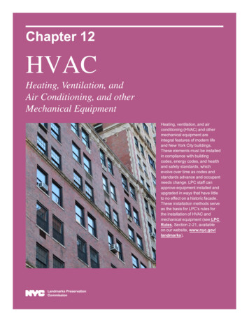
GENERAL INFORMATIONPART 1. GENERAL INFORMATIONA. HOW IT OPERATESWhen the room thermostat calls for heat, the Munchkin control board will start the circulator and startto monitor the return temperature of the system before the heater will begin to heat the water. Oncethe controller has sensed a drop in the return water temperature below the temperature set pointminus the differential set point, the heater will start to heat the water. This eliminates the Munchkinstarting every time the thermostat calls for heat. This feature keeps the system from short cycling.Once the system has sensed the temperature difference, the Munchkin will activate the blower motorfor 5 seconds to pre-purge the system before starting the Munchkin. The Munchkin controller will nowstart to modulate the pre-mix burner based on analyzing the return temperature, supply watertemperature and the set point temperature. By compiling this information, the controller utilizes analgorithm to fully adjust the firing rate while maintaining the desired output temperature. The pre-mixburner fan has a direct drive current low-voltage motor with a pulse relay counting. This system allowsprecise control over the fan speed and combustion air volumes. Coupled with the Krom Schroder gasvalve and the air/gas mixing system which are set to provide a one-to-one ratio of precisely measuredvolumes of fuel to air, an accurate and instant burner output is achieved. This keeps the Munchkinrunning at the highest efficiency.When the thermostat is satisfied, the Munchkin will then go through a 4 second post-purge cycle beforeshutting off. Every Munchkin heater is equipped with a display which will read the outlet temperature ofthe heater and then will illuminate a green light showing flame on. If a problem occurs, the front indicatorlight will turn red and the display will read a fault code; see Part 7, Section B/C.B. MUNCHKIN RATINGS AND DIMENSIONSPERFORMANCE RATINGModel399MInput Modulation100,000 to 399,000DOE Heating93,000 to 279,000Combustion Efficiency95%Thermal Efficiency93.35%AFUE*93%Shipping Weight252 lbs.CONNECTION SIZESModel399MSupply/ReturnConnection2" NPTGas ConnectionSize1-1/4"Vent Dia.4"RECOMMENDED SERVICE CLEARANCES(NOTE: The Munchkinis rated at zeroclearance tocombustibles.)15"24"FRONT24"12"Figure 1-1412"
GENERAL INFORMATIONDIMENSIONSFigure 1-2C. PRE-INSTALLATION REQUIREMENTSThe Munchkin is designed for installation on non-rated flooring, in alcoves, basements, utility rooms,and closet but never a bedroom closet. Choose a location for your Munchkin, centralized to the pipingsystem, along with consideration for Electrical (Part 2), Gas Connection (Part 3) and Venting (Part 4).This boiler needs to be installed on a level floor. This will assure the proper flow to the condensate drainin the bottom of the boiler.5
GENERAL INFORMATION / ELECTRICALNOTE: It is important to refer to the site installation checklist in the back of the manualto assure proper and effective installationCAUTIONThe Munchkin is certified as an indoor appliance. Do not install the Munchkinoutdoors or locate where it will be exposed to freezing temperature. This includes allrelated piping and components. If the Munchkin is subjected to flood water orsubmersed in water, the Munchkin must be replaced.NOTE: Service clearance of the Munchkin1. The front of the appliance needs 24" of clearance for service minimum. It may havea non-rated or combustible door or access panel and must have a minimum of 24"clearance.2. The left side of the heater is 12" clearance3. The right side of the heater is 12" clearance4. The top of the heater is 15" clearance.If the Munchkin is set up for liquefied petroleum (LP) gas, some geographic areas follow the UniformMechanical Code, section 304.6, “Liquefied petroleum gas burning appliances shall not be installed ina pit, basement or similar location where heavier-than-air gas might collect. Appliances so fueled, shallnot be installed in a below grade under-floor space or basement unless such location is provided withan approved means for removal of unburned gas.”CAUTIONCondensation removal: This is a condensing, high efficiency appliance, thereforecondensation removal must be addressed to avoid damage to surrounding area orappliance. See Part (4) Section E for Condensate Requirements.WARNINGD. PRESSURE RELIEF VALVEA pressure relief valve is installed into the front right side manifold. We recommend a WATTS ¾"M 335 MI valve or equivalent and meets the requirements of ANSI/ASME Heater and PressureVessel Code, Section IV or CSA B51; Heater, Pressure Vessel and Piping Code as applicable forheating heaters. A ¾" pipe must be directed to a floor drain or suitable location within 6" of a drainor floor. Protect from freezing, do not plug or cap pressure relief valve. Serious explosion causingproperty damage and or loss of life could result. Under no circumstances should the relief valvebe eliminated, capped or plugged.PART 2. ELECTRICALA. ELECTRICAL CONNECTIONThe electrical connection for the Munchkin is on the left hand side of the unit. There is a ½” knockoutlocation for an electrical connection for both the incoming power and the central heating circulatorconnection. All electrical wiring must be performed by a qualified licensed electrician in accordancewith National Electrical Code ANSI Z223.1/NFPA 54 to and/or the Canadian Electrical Code, Part 1 CSA6
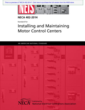
ELECTRICALC22.1, or to the applicable codes and standards. For your convenience, we have labeled all the wiresthat need to be connected to operate the Munchkin.CAUTIONElectrical wiring on the Incoming Power and Central Heating Circulator shall beconnected directly to the intended connection source and not be connected togetherinside the electric box provided. An Electrical Short will result and the Control boardwill have to be replaced! If Electrical Requirements of the Central Heating Circulatorexceeds 4 amps (or 3 amps on HA models only) please follow the wiring diagrams onPage 8, Figures 2-1, 2-2 and 2-3.The electrical requirements are for standard 120 volts, 60 Hz 15 Amp service. This unit is wired with#18 awg and fused for no more than 15 Amps.DANGERIT IS EXTREMELY IMPORTANT THAT THIS UNIT BE PROPERLY GROUNDED!DANGERIT IS VERY IMPORTANT THAT THE BUILDING GROUND IS INSPECTED BY AQUALIFIED ELECTRICIAN PRIOR TO MAKING THIS CONNECTION!There are two ground points in the electrical compartment that must be connected to the buildingground system. Connect the building ground to the green ground screw and the green ground wireinside electrical box provided.The Incoming Power Supply is connected to the Black (Hot) and the White (Neutral).The MunchkinControl board is polarity sensitive. If the polarity is reversed, the Munchkin control will not sense aflame and lock out the system. The Orange and Brown wire are provided to the supply of 120 volts tothe Central Heating Circulator. Connect the Orange (Hot) and the Brown (Neutral) directly to the CentralHeating Circulator.DANGERThe Orange wire for the Central Heating Circulator is Switched Hot and must have awire nut if not connected to the Central Heating Circulator. Failure to follow thisinstruction will result in a short, and the Control Board will have to be replaced.Connect the gray wires to your heating thermostat (TT) connection. Your thermostat heat anticipatorsetting is .056 amp.CAUTIONDo not power zone valves directly from the heater transformer. Doing so will greatlyreduce the life of the transformer. Use a separate transformer sized to handle the totalelectric load of all zone valves.It is important that the electrical power is not turned on at this time. Double check all connections and thenturn the power on. The display that is provided with the Munchkin should now be reading the outlettemperature. Note: see Part 6/Startup Procedure section in the manual to change the temperature settingor run the heater.7
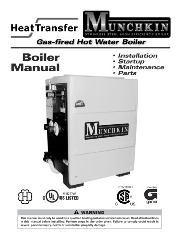
ELECTRICAL / GAS CONNECTIONDIAGRAM "A"DIAGRAM "B"WIRING DIAGRAM CONNECTING TO CIRCULATORWIRING DIAGRAM WITHOUT CONNECTION TO EN (GROUND)WHITE(NEUTRAL)BROWN (NEUTRAL)ORTGRAYNORMALLY OPENTHERMOSTATCONNECTIONORANGE (HOT)TGREEN (GROUND)NORMALLY OPENTHERMOSTATCONNECTIONBROWN (NEUTRAL)ORANGE (HOT)BLACKBRANGEOWGR NEENGREEN (GROUND)WHITE (NEUTRAL)IMPORTANT NOTE:BE CERTAIN THAT THE ORANGEWIRE IS SECURELY CAPED.FAILURE TO DO SO COULDRESULT IN INJURY OR FIREAND COULD DAMAGE THE DBUSELECTRICALSWITCH JUNCTION BOX120V 60 HZELECTRICALSWITCH JUNCTION BOX120V 60 HZFigure 2-1: Connection Wiring Directly toCentral Heating CirculatorZONETHERMOSTATR845ASWITCHINGRELAY ZONEBOILER"TT"GRAY1K15Figure 2-2: Connection Wiring without WiringCentral Heating CirculatorNote to Electrical Contractor: The orangewire is 120 Volt/4 Amp maximum for centralheating circulator only. Loads greater than 4amps or 3 amps for HA models only will blow thefuse on the board. The brown wire is the neutral wire for the central heating pump only.3TT1K11L1 HOT (BLACK)120 VOLT21K264ZONECIRCULATORL2 NEUTRAL(WHITE)BOILER"TT"GRAYFigure 2-3: For circulator amp loads greaterthan 4 amps (3 amps for “HA” models) use thewiring diagram shown at left. The brown andorange wires on the Munchkin boiler will not beused in this application and should beterminated so they do not cause a short circuit.PART 3. GAS CONNECTIONWARNINGFailure to follow all precautions could result in fire, explosion or death!8
GAS CONNECTIONA. GAS CONNECTIONThe gas supply shall have a maximum inletpressure of less than 14" water column (350mm), ½ pound pressure (3.5 kPa), and aminimum of 7" water column. The entirepiping system, gas meter and regulator mustbe sized properly to prevent pressure dropgreater than 0.5" as stated in the National FuelGas Code. This information is listed on therating plate. It is very important that you areconnected to the type of gas as noted on therating plate. "LP" for liquefied petroleum,propane gas or, "Nat" natural or city gas. Allgas connections must be approved by the local gas supplier, or utility in addition to the governingauthority, prior to turning the gas supply on. The nipple provided is 1¼" and it is mandatory that a 1 x1¼" reducing coupling (provided) is used, threaded into the branch of a 1¼" tee, and a drip legfabricated, as per the National Fuel Gas code. You must ensure that the entire gas line to theconnection at the Munchkin is no smaller than 1¼". Once all the inspections have been performed,the piping must be leak tested. If the leak test requirement is a higher test pressure than the maximuminlet pressure, you must isolate the Munchkin from the gas line. In order to do this, you must shut thegas off using factory and field-installed gas cocks (following the lighting instructions in Part 6 SectionB.) This will prevent high pressure. Failure to do so may damage the gas valve. In the event the gasvalve is exposed to a pressure greater than ½ PSI, 14" water column, the gas valve must be replaced.Never use an open flame (match, lighter, etc.) to check gas connections.B. GAS PIPING1. Run the gas supply line in accordance with all applicable codes.2. Locate and install manual shutoff valves in accordance with state and local requirements.C. GAS TABLERefer to Table (1) to size the supply piping to minimize pressure drop between meter or regulatorand unit.Maximum Capacity of Pipe in Cubic Feet of Gas per Hour for Gas Pressures of 0.5 psi or Less and aPressure Drop of 0.3 Inch water Column(TABLE 1)NominalIron Pipe InternalSizeDiameter(inches) (inches) 103/4.82427811.0495201 1/41.380 1,0501 1/21.610 1,600(Based on a 0.60 Specific Gravity Gas)Length of Pipe 5011521544067060 70105 96195 180400 370610 320}BTU'SPERHOURX 1,000It is recommended that a soapy solution be used to detect leaks. Bubbles will appear on the pipe toindicate a leak is present. The gas piping must be sized for the proper flow and length of pipe, toavoid pressure drop. Both the gas meter and the gas regulator must be properly sized for the totalgas load. If you experience a pressure drop greater than 1" WC, the meter, regulator or gas line isundersized or in need of service. You can attach a manometer to the incoming gas drip leg, by9
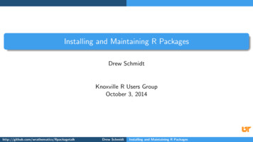
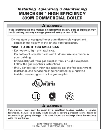
GAS CONNECTIONremoving the cap and installing the manometer. The gas pressure must remain between 7" and 14"during stand-by (static) mode and while in operating (dynamic) mode. If an in-line regulator is used,it must be a minimum of 10 feet from the Munchkin. It is very important that the gas line is properly purged by the gas supplier or utility. Failure to properly purge the lines or improper line sizing, will result in ignition failure. This problem is especially noticeable in NEW LP installations andalso in empty tank situations. This can also occur when a utility company shuts off service to an areato provide maintenance to their lines. This gas valve must not be replaced with a conventional gasvalve under any circumstances. As an additional safety feature, this gas valve has a flanged connection to the Venturi and blower.MUNCHKIN BURNERTECH GAS VALVE110 VOLT AC ELECTRICAL CONNECTIONVENTURIOUTLET PRESSURE TAP(NOTE: A NEGATIVE READING WILL BEMEASURED WHILE THE FAN ISIN OPERATION)INLET PRESSURE TAP(NOTE: INLET GAS PRESSURE CANBE MEASURED TO ASSUREPROPER GAS SUPPLY)THROTTLE ADJUSTER(NOTE: IF FOR ANY REASON THE THROTTLENEEDS TO BE ADJUSTED,IT IS VERY IMPORTANT THAT A " COMBUSTIONANALYZER " BE USED TO ENSURE SAFE AND PROPER OPERATIONTURN THE ADJUSTER TO THE ( ) TO INCREASE GASOR TO THE (-) TO DECREASE THE GAS SUPPLY.THIS ADJUSTMENT COULD AFFECT THE CO/CO % LEVELS. 2MAKE SURE THE LEVELS CORRESPOND TO THE CHART INFIG. 3-2 COMBUSTION SETTINGS)Fig. 3-1WARNINGFailure to follow all precautions could result in fire, explosion or death!COMBUSTION SETTINGSHIGH FIRING RATES and LOW FIRING RATES ON ALL MODELSNatural GasCarbon CO ppmMonoxideCarbon CO 2%DioxideFig. 3-210Propane LPlowhighlowhigh0–20 ppm70 ppm–135 ppm0–20 ppm80–150 ppm8-1/2% – 9-1/2%8-1/2% – 9-1/2%9-1/2% – 10-1/2%9-1/2% – 10-1/2%
VENTINGPART 4. VENTINGA. GENERAL1. Install the boiler venting system in accordance with these instructions and with theNational Fuel Gas Code, ANSI Z223.1/NFPA54, CAN/CGA B149, and/or applicable provisions of local building codes.2. This boiler is a direct vent appliance and islisted as a Category IV appliance withUnderwriters Laboratories, Inc. VENT ANDINTAKE AIR PIPEWARNINGThis vent system will operate with a positivepressure in the pipe. Do not connect ventconnectors serving appliances vented by naturaldraft into any portion of mechanical draft systemsoperating under positive pressure.WARNINGFollow these venting instructions carefully. Failureto do so may result in severe personal injury, death,or substantial property damage.B. APPROVED MATERIALS FOR EXHAUSTVENT AND INTAKE AIR PIPE1. Use only Non Foam Core venting material.The following materials are approved for useas vent pipe for this boiler:a. Non Foam Core PVC (Polyvinyl Chloride)Pipe conforming to ASTM D-1784 Class12454-B (formerly designated Type 1, Grade1).b. Non Foam Core CPVC (Chlorinated PolyvinylChloride) Pipe conforming to ASTM D-1784Class 23447-B (formerly designated Type IV,Grade 1).c. Non Foam Core ABS (AcrylonitrileButadiene- Styrene) Pipe conforming toASTM D3965 Class 3-2-2-2-2.WARNINGDo not use Foam Core Pipe in any portion of theexhaust piping from this boiler. Use of Foam CorePipe may result in severe personal injury, death, orsubstantial property damage.2. Cellular foam core piping may be used on airinlet piping only. Never use cellular foam corematerial for exhaust piping.C. EXHAUST/VENT / AIR INTAKE PIPELOCATION1. Determine exhaust vent location:a. The vent piping for this boiler is approved forzero clearance to combustible construction.b. See Figure 4.1 for an illustration of clearances for location of exit terminals of directvent venting systems.c. This boiler vent system shall terminate atleast 3 feet (0.9 m) above any forced airintake located within 10 ft (3 m). Note: thisdoes not apply to the combustion air intakeof a direct-vent appliance.d. Provide a minimum of 1 foot distance fromany door, operable window, or gravity intakeinto any building.e. Provide a minimum of 1 foot clearance fromthe bottom of the exit terminal above theexpected snow accumulation level. Snowremoval may be necessary to maintainclearance.f. Provide 4 feet horizontal clearance fromelectrical meters, gas meters, gas regulators,and relief equipment. In no case shall theexit terminal be above or below the aforementioned equipment unless the 4 foot horizontal distance is maintained.g. Do not locate the exit terminal over publicwalkways where condensate could dripand/or freeze and create a nuisance or hazard.h. When adjacent to a public walkway, locateexit terminal at least 7 feet above grade.i. Do not locate the exit termination directlyunder roof overhangs to prevent iciclesfrom forming.j. Provide 3 feet clearance from the inside corner of adjacent walls.2. Determine air intake pipe location.a. Provide 1 foot clearance from the bottom ofthe air inlet pipe and the level of maximumsnow accumulation. Snow removal may benecessary to maintain clearances.b. Do not locate air intake pipe in a parking areawhere machinery may damage the pipe.c. When venting with a two pipe system, maximum distance between air intake andexhaust vent is 6 feet (1.8 m). Minimum distance between exhaust vent and air intakeon single boiler is 8” (0.2 m) center-to-center. Minimum distance between vents andintakes on multiple boilers is 8” (0.2 m) center-to-center. See Figure 4.2.11
VENTINGLocation of exit terminals of mechanical draft and direct-vent venting systems.(Reference: National Fuel Gas Code ANSI Z223.1/NFPA 54 2002).Fig. 4-1Fig. 4-2 Multiple Vent Spacing**Note: Exhaust must extend out 1 foot.Fig. 4-3 Multiple Stainless Steel Vertical VentKit Installation – Front ViewFig. 4-4 Multiple Stainless Steel Horizontal Vent Kit Installation – Front View12
VENTINGD. EXHAUST VENT AND INTAKE AIR PIPESIZING1. For the 399M the exhaust vent and air intakepipes should be 4" Schedule 40 or 80.2. The total combined equivalent length ofexhaust vent and intake air pipe should notexceed 85 feet.a. The equivalent length of elbows, tees, andother fittings are listed in the Friction LossTable 4.1.Table 4.1FRICTION LOSS EQUIVALENT IN PIPING AND FITTINGSFITTINGS OR PIPINGEQUIVALENT FEETa. Transitions should always be made in vertical sections of pipe to prevent the condensate from pooling in the vent pipe.b. Use a 6” x 4” reducing coupling to transitionfrom the 399M boiler connections to 6”vent.c. The maximum equivalent length for theincreased diameter vent pipes is 125 feet.d. If the transition occurs at a distance greaterthan 15 equivalent feet from the boiler, themaximum equivalent length will be reduced.See Table 4.2. Standard Vent Pipe is 4" andOversized Vent Pipe is 6" for the 399M.Table 4.2: Vent Termination Kits1'TransitionPoint(ft fromboilerTEL ofStandard 2"or 3" VentPipe 1/2431034"6"90 DEGREE ELBOW*3'45 DEGREE ELBOWCOUPLINGTEL ofOversized 3" MaximumTEL of allor 4" Vent VentPipe (ft)Pipe (ft)AIR INLET TEE0'0'25STRAIGHT PIPE1'0.5'3060V2000 4" VENT KIT1'N/A3570269640808-1/288-1/2None85085*Friction loss for long radius elbow is 1 foot lessb. For example: If the exhaust vent has two 90 elbows and 10 feet of PVC pipe we will calculate:Exhaust Vent Pipe Equivalent Length (2x5) 10 20 feetFurther, if the intake air pipe has two 90 elbows, one 45 elbow and 10 feet of PVCpipe, the following calculation applies:Air Intake Pipe Equivalent Length (2x5) 3 10 23 feetFinally, if a concentric vent kit is used wefind:Total Combined Equivalent Length 20 23 3 46 feetTherefore, the total combined equivalentlength is 46 feet which is well below themaximum of 85 feet.c. The intake air pipe and the exhaust vent areintended to penetrate the same wall or roofof the building.d. Effort should be made to keep a minimumdifference in equivalent length between theair intake pipe and the exhaust vent.4. The minimum combined equivalent length is16 equivalent feet.TEL Total Equivalent LengthE. EXHAUST VENT AND AIR INTAKE PIPEINSTALLATION1. On the 399M Boiler the 4" exhaust vent connection is located at the rear of the boiler andthe air intake is higher and toward the left sidewhen the boiler is viewed from the front. Theair intake connection is intended for a slip fit.No sealant or adhesive is required.2. Use only solid PVC, CPVC, or ABS schedule40 or 80 pipe. FOAM CORE PIPING IS NOTAPPROVED.3. Remove all burrs and debris from joints andfittings.4. All joints must be properly cleaned, primed,and cemented. Use only cement and primerapproved for use with the pipe material.Cement must conform to ASTM D2564 forPVC or CPVC pipe and ASTM D2235 for ABSpipe.5. The maximum combined equivalent lengthcan be extended by increasing the diameterof the vent pipe. However, the transitionsshould begin a minimum of 15 equivalent feetfrom the boiler.13
VENTINGWARNINGAll joints of positive pressure vent systems must besealed completely to prevent leakage of flueproducts into the living space.5. Horizontal lengths of exhaust vent must slopeback towards the boiler not less than ¼" perfoot to allow condensate to drain from thevent pipe. If the vent pipe must be pipedaround an obstacle that causes a low point inthe pipe, a drain pipe must be connected toallow condensate to drain.6. All piping must be fully supported. Use pipehangers at a minimum of 4 foot intervals toprevent sagging of the pipe where condensate may form.7. Do not use the boiler to support any piping.8. A screened straight coupling is provided withthe boiler for use as an outside exhaust termination.9. A screened inlet air tee is provided with theboiler to be used as an outside intake termination.10. The following is an optional intake air/exhaustvent termination available from Heat TransferProducts, Inc. for the 399M: 4” Stainless SteelVent Termination Kit – V2000.DANGERThe Munchkin is not intended to be common vented with any otherexisting appliance!F. HEATER REMOVAL FROM A COMMON VENT SYSTEMAt the time of removal of an existing heater, the following steps shall be followed with each appliance remaining connected to the common venting system placed in operation, while the other appliances remaining connected to common venting system are not operating.1. Seal any unused openings in the common venting system.2. Visually inspect the venting system for proper size and horizontal pitch to determine if thereis blockage, leakage, corrosion or other deficiencies that could cause an unsafe condition.3. If practical, close all building doors, windows and all doors between the space in which theappliance remains connected to the common venting system located and other spaces in thebuilding. Turn on clothes dryers and any appliances not connected to the common ventingsystem. Turn on any exhaust fans, such as range hoods and bathroom exhausts, at maximumspeed. Do not operate a summer exhaust fan. Close all fireplace dampers.4. Place in operation the appliance being inspected. Follow the lighting instructions. Adjust thethermostat so the appliance will operate continuously.5. Test for spillage at the draft hood relief opening after 5 minutes of main burner operation. Usethe flame of a match or candle or smoke from a cigarette.6. After it has been determined that each appliance remaining connected to common ventingsystem properly vents when tested as outlined, return doors, windows, exhaust fans, fireplace dampers and any other gas burning appliance to their previous condition of use.7. Any improper operation of the common venting system should be corrected so the installation conforms with the National Fuel Gas Code, ANSI Z223.1. When resizing any portion ofthe common venting system, the common venting system should be resized to approach theminimum size as determined using the appropriate tables in Appendix G in the National FuelGas Code , ANSI Z 223.114
VENTINGDIAGRAMS FOR SIDEWALL VENTING**IMPORTANT NOTE: All vent pipes must be glued, properly supported and t
This eliminates the Munchkin starting every time the thermostat calls for heat. This feature keeps the system from short cycling. Once the system has sensed the temperature difference, the Munchkin will activate the blower motor for 5 seconds to pre-purge the system before starting the Munchkin . The Munchkin controller will now