Transcription
30XAVTouch Pilot ControlOperation instructions
CONTENTS1 - SAFETY CONSIDERATIONS. 41.1 - Safety guidelines. .41.2 - Safety precautions. .42 - CONTROL SYSTEM OVERVIEW. 42.1 - Control system. .42.2 - System functionalities. .42.3 - Operating modes. .53 - HARDWARE DESCRIPTION. 63.1 - General description. .63.2 - Electrical box. .63.3 - Power supply to boards. .63.4 - Light emitting diodes on boards. .63.5 - Pressure sensors. .63.6 - Temperature sensors. .73.7 - Actuators. .73.8 - Connections at the user terminal block. .84 - SETTING UP THE TOUCH PILOT CONTROL. 94.1 - Touch Pilot user interface. .94.2 - Screens overview. .104.3 - Start/Stop screen. .114.4 - User Login screen. .114.5 - Main menu. .114.6 - Configuration menu. .124.7 - Override screen. .134.8 - Trendings screen. .134.9 - Web interface. .145 - TOUCH PILOT INTERFACE DETAILS. 155.1 - Menu structure. .155.2 - Detailed menu description. .165.3 - Alarms menu . .205.4 - Configuration menu. .206 - CONTROL OPERATION. 236.1 - Start/Stop control . .236.2 - Unit stop function. .236.3 - Pumps control. .236.4 - Control point. .246.5 - Capacity limitation. .256.6 - Capacity control. .256.7 - Night mode. .266.8 - Head pressure control. .266.9 - Circuit lead/lag selection. .266.10 - Time schedule function. .266.11 - Master/slave assembly (option 58). .266.12 - Energy management module (option 156). .276.13 - Evaporator heater (option 41). .276.14 - Refrigerant gas leak detection (option 159). .276.15 - Low noise (option 257). .276.16 - BACnet (option 149). .276.17 - Hydronic kit (option 116X). .276.18 - Variable water flow control (option 299). .277 - DIAGNOSTICS – TROUBLESHOOTING. 287.1 - E-mail notifications. .287.2 - Displaying alarms. .287.3 - Current alarms. .287.4 - Resetting alarms. .287.5 - Alarm history. .287.6 - Alarm codes. .29The cover photos are solely for illustration and forms no part of any offer for sale or any sale contract. The manufacturerreserves the right to change the design at any time without notice.2
PREFACEThe goal of this document is to give a broad overview ofthe main functions of the Touch Pilot system used tocontrol 30XAV single-circuit air-cooled liquid chillers.Instructions in this manual are given as a guide to goodpractice in the installation, start-up and operation of thecontrol system. This document does not contain full serviceprocedures for the correct operation of the equipment. Thesupport of a qualified Carrier Service Engineer is stronglyrecommended to ensure optimal operation of theequipment as well as the optimization of all availablefunctionalities.IMPORTANT: All screenshots of the interface providedin this manual include text in English. After changing thelanguage of the system, all labels will be displayed in thelanguage selected by the user.Please read all instructions prior to proceedingwith any work. Pay attention to all safetywarnings.Note that this document may refer to optional componentsand certain functions, options or accessories may not beavailable for the specific unit. The cover images are solelyfor illustration and form no part of any offer for sale or anysale contract.The information provided herein is solely for the purposeof allowing customers to operate and service Carriermanufactured equipment and it is not to be reproduced,modified or used for any other purpose without the priorconsent of Carrier Corporation.Acronyms/abbreviationsIn this manual, the refrigeration circuits are called circuit Aand circuit B. Fans in circuit A are referred to as Fan A1,Fan A2, etc., whereas fans in circuit B are referred to asFan B1, Fan B2, etc.BMSCCNEMMEXVLEDLENOATPSMVLTNetwork modeLocal-OffLocal-OnLocal-ScheduleMaster modeRemote modeBuilding Management SystemCarrier Comfort NetworkEnergy Management ModuleElectronic Expansion ValveLight Emitting DiodeSensor Bus (internal communication bus linking the basicboard to slave boards)Outdoor Air TemperaturePlant System ManagerVariable Speed DriveOperating type: NetworkOperating type: Local OffOperating type: Local On modeOperating type: Local On following a time scheduleOperating type: master unit (master/slave assembly)Operating type: by remote contacts3
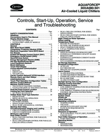
1 - SAFETY CONSIDERATIONS2 - CONTROL SYSTEM OVERVIEW1.1 - Safety guidelines2.1 - Control systemInstallation, start-up and servicing of equipment can behazardous if certain factors particular to the installationare not considered: operating pressures, electricalcomponents, voltages and the installation site (elevatedplinths and built-up structures).Touch Pilot is a system used to control the operation of30XAV single-circuit and dual-circuit air-cooled liquidchillers.Only qualified installation engineers and fully trainedtechnicians are authorised to install and start the equipment.All instructions and recommendations provided in theservice guide, installation and operation manuals, as well ason tags and labels fixed to the equipment, components andother accompanying parts supplied separately, must be read,understood and followed. Failure to comply with theinstructions provided by the manufacturer may result ininjury or product damage. Apply all safety standards and practices.Wear safety glasses and gloves.Use the proper tools to move heavy objects. Moveunits carefully and set them down gently.1.2 - Safety precautionsOnly personnel qualified in accordance with IEC(International Electrotechnical Commission)recommendations may be permitted access to electricalcomponents. It is particularly recommended that allsources of electricity to the unit should be shut off beforeany work is begun. Shut off the main power supply at themain circuit breaker or isolator.CAUTION: The equipment uses and emits electromagneticsignals. Tests have shown that the equipment conforms toall applicable codes with respect to electromagneticcompatibility.RISK OF ELECTROCUTION: Even when the maincircuit breaker or isolator is switched off, specific circuitsmay still be energised as they may be connected to aseparate power source.RISK OF BURNS: Electrical currents may causecomponents to get hot. Handle power cable, electricalcables and conduits, terminal box covers and motor frameswith great care.4This document may refer to optional components andcertain functions, options or accessories may not beavailable for the specific unit.2.2 - System functionalitiesThe system controls the start-up of the compressorsneeded to maintain the desired heat exchanger enteringand leaving water temperature. It constantly manages theoperation of the fans in order to maintain the correctcondensing pressure in each circuit and monitors safetydevices that protect the unit against failure and guaranteeits optimal functioning.Touch Pilot control system: Allows users to control the unit via the Touch Pilotuser interface (7-inch colour touch screen) Provides web connectivity technology Includes the trending functionality Supports Carrier Connect Services (Remoteconnectivity, alarm notification, remote access,performance and operation automatic reporting,technical advice) Supports Carrier Advanced Plant System Manager formultiple chillers configuration Provides direct BMS integration capabilities(BACnet IP)
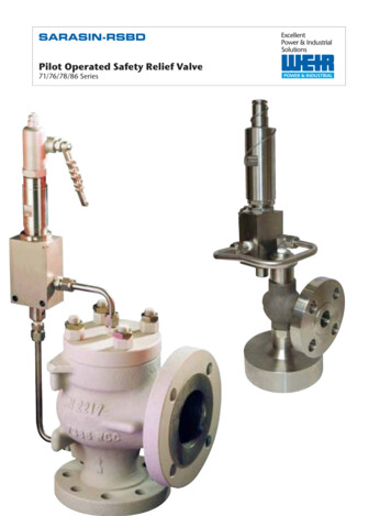
TOUCH PILOT CONTROLChillerplantMetersValvesPumpsBACnet IPBuilding Automation SystemTouch PilotcontrolCarrierConnect ServicesChillersBACnet IPBuilding Automation SystemCarrierConnect ServicesStandalone chiller2.3 - Operating modesThe control system can operate in three independentmodes: Local mode: The unit is controlled by commands fromthe user interface. Remote mode: The unit is controlled by dry contacts. Network mode: The unit is controlled by networkcommands (CCN or BACnet). Data communicationcable is used to connect the unit to the CCNcommunication bus.The operating mode can be selected with the Start/Stopbutton (see also section 4.3). When the Touch Pilot systemoperates autonomously (Local or Remote), it retains all ofits control capabilities but does not offer any of thefeatures of the Network. The Network emergency stopcommand stops the unit regardless of its active operatingtype.5
3 - HARDWARE DESCRIPTION3.1 - General descriptionEach circuit is by default fitted with one SIOB board usedto manage all major inputs and outputs of the controller.The control system includes variators for compressor andfan control, as well as AUX1 boards used to manageadditional inputs and outputs. Options such as hydraulickit or master/slave assembly control require an additionalAUX1 board. Energy management module requires theinstallation of NRCP2 board.All boards communicate via an internal LEN bus. Themain board continuously monitors the informationreceived from various pressure and temperature probesand accordingly starts the program that controls the unit.The unit is equipped with the Touch Pilot user interface(7-inch touch screen).3.2 - Electrical boxThe electrical box includes all boards controlling the unitand the Touch Pilot user interface.NOTE: The pictures are for reference only.3.3 - Power supply to boards3.5 - Pressure sensorsAll boards are supplied from a common 24 VAC supplyreferred to earth.Two types of electronic sensors (high and low pressure)are used to measure various pressures in each circuit.CAUTION: Maintain correct polarity whenconnecting the power supply to the boards,otherwise the boards may be damaged.In the event of a power supply interrupt, the unit restartsautomatically without the need for an external command.However, any faults active when the supply is interruptedare saved and may in certain cases prevent a given circuitor the unit from restarting.3.4 - Light emitting diodes on boardsAll boards continuously check and indicate the properoperation of their electronic circuits. A light emitting diode(LED) lights on each board when it is operating properly. 6The red LED flashing for a two-second period on theSIOB board indicates correct operation. A differentrate indicates a board or a software failure.The green LED flashes continuously on all boards toshow that the board is communicating correctly overits internal bus. If the green LED is not flashing, thisindicates a LEN bus wiring problem.These electronic sensors deliver 0 to 5 VDC. The sensorsare connected to the SIOB board. Liquid pressure sensorsare connected to the AUX1 board and water pressuresensors of the optional hydraulic kit are connected to theadditional AUX1 board.Discharge pressure sensors (high pressure type)These sensors measure the discharge pressure in eachcircuit. They are used to control head pressure. Dischargepressure sensors are mounted on the discharge line pipingof each circuit.Suction pressure sensors (low pressure type)These sensors measure the suction pressure in each circuit.They are used for EXV control. Suction pressure sensorsare located on the suction piping of each circuit.Oil pressure sensors (high pressure type)These sensors measure the oil pressure of eachcompressor. Oil pressure sensors are located at the oil portof the compressor. The suction pressure is subtracted fromthis value to arrive at the differential oil pressure.Economizer pressure sensors (high pressure type)These sensors measure the pressure on the economizerline. They are used to control the economizer performance.
Liquid pressure sensors (high pressure type)These sensors measure the liquid pressure after the coils ineach circuit.They are used for EXV control.Compressor motor temperature sensorsThese sensors are used to control the motor temperatureof each compressor.Water pressure sensors (low pressure type)These sensors measure the water pressure before thepump and after the evaporator. Only units fitted with theoptional hydronic kit have these sensors included.Temperature setpoint reset sensor (optional)This sensor measures the space (room) temperature forthe purpose of setpoint reset. Only units with the optionalenergy management module are fitted with this sensor.3.6 - Temperature sensorsMaster/slave common fluid temperature sensor (optional)This sensor is used to control the operation of chillers inthe master/slave assembly. This sensor is located on thecommon chilled leaving piping. Only units in the master/slave configuration are fitted with this sensor.Temperature sensors constantly measure the temperatureof various components of the unit, ensuring the correctoperation of the system.Evaporator entering and leaving water temperaturesensorsThe evaporator entering and leaving water temperaturesensors are installed in the entering and leaving side waterbox. They are used for capacity control and safetypurposes.3.7 - ActuatorsOutdoor air temperature sensorThis sensor is mounted on the control box of air-cooledunits. Outdoor temperature sensor is used for start-up,setpoint temperature reset and freeze protection control.Electronic expansion valveThe electronic expansion valve (EXV) is used to adjust therefrigerant flow to changes in the operating conditions ofthe machine. To adjust the refrigerant flow, a piston movesconstantly up or down to vary the cross-section of therefrigerant path. This piston is driven by an electronicallycontrolled linear stepper motor. The high degree ofaccuracy with which the piston is positioned providesprecise control of the refrigerant flow.Suction gas temperature sensorThis sensor is used to control the suction gas temperature.It is located at the suction side of each compressor.Discharge gas temperature sensorThis sensor is used to control the discharge gastemperature, and permits control of the dischargesuperheat temperature. It is located at the discharge sideof each compressor.Liquid line temperature sensorsThese sensors are used to control the liquid linetemperature in each circuit. They are used for EXVcontrol to maintain the subcooling setpoint.Evaporator pumpsThe controller can regulate one or two evaporator pumpsand takes care of the automatic changeover between thesepumps (see also section 6.3).Water flow switchFor units without internal pumps, the water flow switchconfiguration allows for the automatic control of theminimum water flow setpoint of the water flow switch.The configuration depends on the unit size and is madeautomatically at the start-up. If the measured water flowrate in the water loop is lower than the configured flowrate, the alarm condition shuts off the unit.Economizer gas temperature sensorsThese sensors measure the economizer line temperature ineach circuit.7
3.8 - Connections at the user terminal blockConnections available at the user terminal block may varydepending on the selected options.3.8.1 - Terminal block connectionsSome contacts can be accessed only when the unitoperates in Remote mode.The following table summarises the connections at theuser terminal block.Terminal block connectionsChannel/ConnectorRemarksSIOB, circuit ASIOB, circuit ASIOB, circuit ASIOB, circuit ASIOB, circuit 3J22Used for the unit on/off control if the unit is in Remote modeThe contact is taken into consideration if the unit is in Remote modeUsed to control demand limit. See section 6.5Indicates alarmsIndicates if the unit is ready to start or operatingNRCP2, EMMDICh 08Capacity limit switch input 2Customer interlockNRCP2, EMMNRCP2, EMMDIDICh 09Ch 10Ice done contactNRCP2, EMMDICh 11aUsed to switch between occupied (closed contact) and unoccupiedmode (open contact)Used to control demand limitUsed for the customer safety loops (if the contact is closed, thechiller is stopped)Used to control the setpoint according to the occupancy scheduleDescriptionBoardOn/Off switchSecond setpoint switchDemand limit switch 1Alarm relayRunning relayOptionalOccupancy override switch3.8.2 - Volt-free on/off contactIf the unit operates in Remote mode, the on/off contacts isas follows:With multiplexingOn/Off contactOffopenCoolingclosedLegend:1. Off: Unit is stopped2. Cooling: Unit is allowed to start in CoolingSetpoint selection contact8Capacity limitation with two contacts is as follows:Demand limit 1 contactDemand limit 2 contact3.8.3 - Volt-free setpoint selection contactThis dry contact input is used to switch between setpoints.It is active only when the control is in Remote mode.CoolingSetpoint 1open3.8.4 - Volt-free demand limit selection contactUp to two dry contacts can be used to limit unit capacity.Note that the second contact is available for units with theenergy management module.Setpoint 2closed100%openopenLimit 1closedopenThe limits are defined in the SETPOINT menu.Limit 2openclosedLimit 3closedclosed
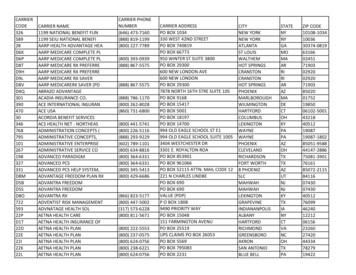
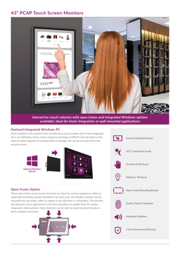
4 - SETTING UP THE TOUCH PILOT CONTROLTOUCH PILOTUSER INTERFACEBMS CONNECTIONCCN RS485StandalonechillerMaster/SlavechillersCCN RS485CCN RS485WEB CONNECTIVITYBMS CONNECTIONBACNET IPEthernetBACnet cuit ALEN busAUX1BoardAAUX1BoardBVFDSERVICE REMOTEMONITORINGNRCP2BoardAUX1BoardCircuit B4.1 - Touch Pilot user interfaceThe Touch Pilot control includes the Touch Pilot userinterface (7-inch touch screen) allowing for easy systemcontrol. It is recommended to use a stylus on the touch screen(the stylus is included with the unit).ConnectionsConnections are located on the bottom side of thecontroller.9
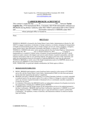
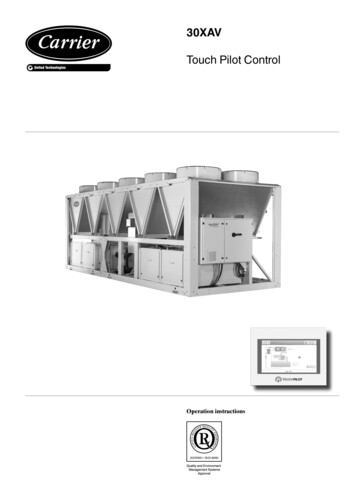
4.2 - Screens overviewAll unit functions can be accessed by pressing the MainTouch Pilot provides access to the following screens: Welcome screenSynoptic screenOperating mode selection screenData/configuration screensPassword entry and language selection screenAlarms screenParameter modification screenTime schedule screenTrending visualisation screenmenu buttonThe bell located in the upper-right part of the screen lightswhen any fault is detected (see also section 7.2).By default, the parameters are presented in metric units.For more information on how to change the system ofmeasurement, see section 4.4.If the interface is not used for a long period, the Welcomescreen is displayed, and then it goes blank. The control isalways active and the operating mode remainsunchanged. Press anywhere on the screen and theWelcome screen will be displayed.4.2.1 - Welcome screenThe Welcome screen is the first screen shown after startingthe Touch Pilot user interface. It displays the applicationname as well as the current software version number.In order to exit the Welcome screen, press theHome button1326541.2.3.4.5.6.EconomizerUnit capacity percentageOutdoor air temperatureStatus screen messageEvaporator inlet and outlet water temperatureSetpointNOTE: The synoptic screen display may vary dependingon pumps configuration.Home buttonInformation message boxThe information displayed in the status bar at the bottomof the screen includes relevant messages regarding thecurrent user action.Software version numberNOTE: In the event of a communication failure,the Settings buttonis displayed.4.2.2 - Touch Pilot synoptic screenThe Synoptic screen provides an overview of the systemcontrol, allowing the user to monitor the vapour-refrigerationcycle. The diagram indicates the current status of the unit,giving information on the unit capacity, the status ofcondenser and evaporator pumps, and the pre-definedsetpoint parameter.10All screens presented further in this manual may display thefollowing messages:MESSAGECOMMUNICATIONFAILURE!ACCESS DENIED!LIMIT EXCEEDED!Save changes?HIGHER FORCE INEFFECT!STATUSEquipment controller did not respond while readingthe table content.Equipment controller denies access to one of thetables.The value entered exceeds the parameter limit.Modifications have been made. The exit must beconfirmed by pressing Save or Cancel.Equipment controller rejects Force or Autocommand.
4.3 - Start/Stop screen4.4 - User Login screenThe Start/Stop screen allows users to select the operatingmode of the unit.4.3.1 - Unit start-upWith the unit in the Local off mode, press the Start/StopThe User Login screen allows the user to select thelanguage of the controller, change the system ofmeasurement (imperial or metric) and enter a password togain access to more control options (default password 11).buttonThe User Login screen can be accessed by pressing theto display the list of operating modes andselect the required mode.Log buttonin the upper-right corner of the screen(see also section 4.2.2).Shows the lastmode selectedSECTION 4.4142NOTE: When entering the menu, please note that thecurrently selected item corresponds to the last runningoperating type.Local OnLocal On: The unit is in the local control mode and allowed tostart.Local ScheduleLocal Schedule: The unit is in the local control mode andallowed to start if the period is occupied.NetworkNetwork: The unit is controlled by network commands andallowed to start if the period is occupied.RemoteRemote: The unit is controlled by external commands andallowed to start if the period is occupied.MasterMaster: The unit operates as the master in the master/slaveassembly and allowed to start if the period is occupied.4.3.2 - Unit stopIn order to stop the unit, press the Start/Stop button1.2.3.4.5.35Cursor indicating the selected languageLogged-in buttonLogged-off buttonSystem of measurement selection: Metric/ImperialPassword dialog boxPassword validation is effective only after pressing theLogged-in button.Once all the changes have been made, pressorto saveto cancel chan
3.2 - Electrical box The electrical box includes all boards controlling the unit and the Touch Pilot user interface. 3.5 - Pressure sensors Two types of electronic sensors (high and low pressure) are used to measure various pressures in each circuit. These electronic sensors deliver 0 to 5 VDC. The sensors are connected to the SIOB board.