Transcription
Distance Relay Element DesignE. O. Schweitzer, III, and Jeff RobertsSchweitzer Engineering Laboratories, Inc.Published in theSEL Journal of Reliable Power, Volume 1, Number 1, July 2010Previously presented at theV Seminário Técnico de Proteção e Controle, August 1995,47th Annual Georgia Tech Protective Relaying Conference, April 1993,46th Annual Conference for Protective Relay Engineers, April 1993,and 1992 ESKOM Protection Conference, November 1992Previous revised edition released March 1993Originally presented at the19th Annual Western Protective Relay Conference, October 1992
DIST ANCERELA y ELEMENTEdmund 0. Schweitzer, IIISchweitzer Engineering Labs.Pullman, Washington USADESIGNJ eff .USAINTRODUCTIONAll distance relays compare voltages and currents to create impedance-plane and directionalcharacteristics. Electromechanical relays do so by developing torques. Most static-analogimplementations use coincidence-timing techniques.Numerical techniques are the newest way to implement distance and directional relayelements. These relays use torque-like products and other methods to accomplish theiroperating characteristics. How do these new techniques relate to the classical electromechanical and static phase-angle comparators?This paper presents basic distance and directional element design. A large emphasis is placedon relating the newer digital and numerical methods to the established electromechanical andstatic-analog methods of designing relay elements.In addition, we discuss:.A new method for characterizing distance elements; i.e., equations for mapping points ona relay characteristic onto a single point on a number line.How multi-input comparators can be viewed as a family of two-input comparators.Which characteristics result from various combinations of comparator inputs.Classical element-security problems and remedies.A new negative-sequence directional element.A different approach to the load-encroachment problem.Finally, we point out a problem with fault-type selection logic which uses the angle betweenthe negative- and zero-sequence currents. It can select the wrong phase for certain resistiveline-line-ground faults. We present a solution to this problem which compares ground andphase fault-resistance estimates.1
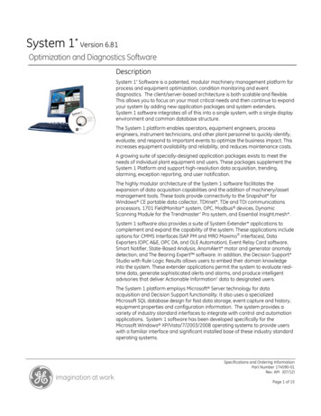
PHASEANGLECOMPARATORSPhase angle comparators test the angle between various voltage and current combinations toproduce directional, reactance, mho, and other characteristics.This section describes three technologies frequently used to compare phasors in relays:induction cylinders, coincidence timers, and digital multiplication.It also presents a newmethod: mapping of a characteristic (e.g., a mho circle) onto a point on a number line.InductionCvlinderPhaseCom aratorFigure 1 is a sketch of an induction cylinder comparator. Assume currents A and B flow inthe windings as shown. The cup tends to rotate in the direction of the rotating flux established by the currents. For example, if B leads A, the cup rotates clockwise to close thecontacts. If A and B are in phase, the net torque is zero and the cup does not move. This isthe only external information available from the relay; either the contacts are open or closed.BtFigure I: Induction Cylinder ComparatorThe equation for the cup torque, T, is:T k,1 A II B I .sin e,where e is the angle between A and B. External circuitry and the coils themselves can beused to modify the torque equation to test other phase relationships.2
Di italProductPhase ComparatorWe can easily emulate the behavior of the inductiondigital relay"S( - cup element using a computerGiven phasors A and B, consider the followingas part of acomplex product: A.B (Ax j.Ay) .(Bx -j.By)A .B x -A x.B y) A x.B x 'ayA .B y J". ( 'aycomplex conjugate)The angle of the product A.B- is the same as the angle of A/B,and is the angle by which Aleads B"Withoutloss of generality , assume our phase reference is B, and phasor A leads phasor B byangle e.In this frame of reference,Bx Ax I B II A I .cos eBy Ay OI A I .sin eand,s IAI.IBI.coseSeparate the real and imaginary j.IAI.IBI.sineparts of S p j .Q A .B-:p Q IAI.IBI.coseIAI.IBI.sineBoth P and Q are two-input phase angle comparators.The P-comparator has a maximum"torque" when A and B are in phase. The Q-comparator has maximum torque when the twoinputs are in quadrature. The Q-comparator is essentially the same as the induction cylinderwith current inputs .In digital relays, is it easy to save the torques (P , Q). We can use the sign of the result(analogous to the cup rotation direction) as well as the magnitudes for tests involving faulttype, sensitivity , etc.Coincidence-Timi Two-InDutPhaseComoaratorTo test the phase angle between sinusoids a and b, we can first convert a and b to squarewaves to derive signals A and B. The time coincidence of A and B is shown in Figure 2.3
Figure 3: Mho Element DerivationLet us test oV and V p using a digital product comparator. Which one should we use --sine orcosine? Since balance (or zero torque) is at 90 , we need to use the cosine comparator,because cos 90 0.Letp Re[oV .V p-]Then:p O represents the area inside the circle of reach r.Zp 0 represents the circle itselfp 0 represents the area outside the circle of reach r.Z(Re real ly, one comparator is required for each zone, and for each voltage and currentinput combination. We can achieve significant economy in processing with no loss inperformance by mapping the points on any mho circle of reach r onto a unique point on anumber line.Recall the mho comparator.P:p Re[oV.Vp*] Re[(r.Z.I -V).Vp1For any V, I, V p combination on a circle of reach r, p is zero. This condition of balanc is:0 Re[(r.Z.I -V).Vp 1Solving for! yields in an equation which is the reach of the mho circle corresponding to thecondition of balance:r EquationRe[Z.I.Vp 151
Observations:1Equation 1 maps all the points on any mho circle of reach I onto a single point on thenumber line. If we need four mho circles, we no longer require four comparators.Instead, we simply need four tests of the calculated I.For example, a Zone 1 mho circle test might test r against 0.85, which represents a reachof 85% .Figure 4 illustrates mapping of mho circles into points for a four zone relay.2.Because V could be zero, we cannot rely on the sign of r to reliably indicate direction.Fortunately, the denominator of the r-equation is a directional element because it tests theangle between a voltage and a current. The sign of the denominator reliably indicatesfault direction.Figure 4: Each Mho Circle Maps onto a Point on the M-LineMUL TIPLE-INPUT COMPARA TORS ARE REALL y A FAMIL yOF TWO-INPUT COMPARA TORSMulti-input comparators are widely used in distance relays. These comparators can be easilyunderstood by representing them as several two-input comparators.The top of Figure 5 shows a three-input comparator. If inputs X, Y, and Z overlap by atleast 90 , then output T asserts.6
What characteristicdoes a multiple-inputcomparator provide?The answer is simply the intersection of three two-input comparator characteristics, usingpairs (X, y ), cY ,Z), and (Z,X). This arrangement is shown in the bottom of Figure 5.Refer to the coincidence timing diagram shown in the middle of Figure 5. Assume signals Xand Yare slightly less than 90 apart, so we barely produce an output if X and Y were theonly two inputs. Input Z does not interfere with the output as long as its leading edge isbetween the leading edges of X and Y. (Assuming all pulses are 180 wide, we need notmake the parallel argument about the trailing edges.)The first condition is X and Y overlap by at least 90 . The two-input comparator XYrepresents this condition. The second condition is that the leading edge of Z lies between theleading edges of X and Y. The zx conditions ensures that Z is within :t90 of x. The YZcondition ensures that Z is within :t90 of Y.If z leads X, then we lose the YZ output. If Z lags y then we lose the ZX output. Therefore Z must be between X and Y, which is the same condition we noted for the three-inputcomparator. E:x--F yZ !I!iIIIIII!OUTPUTT iI -rTl--J-"-lIL- :III! I!!t-.o!IIL-IFigure 5: Coincidence-Timing Multi-Input LogicA QUICKREVIEWOF MHOELEMENTPOLARIZINGCHOICESMho elements compare the angle between (Z.I -V) and V p. There are many choices for thepolarizing voltage, V P" Table 1 reviews some of them.'7
Table I: Mho Element Polarizing ChoicesOperatingPolarizing(Z.lbc -Vbc)(self pol.)VbcCharacteristicGeneral Comments.Unreliable.Noexpansion.for zero-voltage faults- .Directionallyinsecure for reverse busfaults during high load. Requires additional directional element.(Z.lbc -Vbc)-j.V.(cross pol.w/o memory) .Goodexpansion for /1- /1faults.Unreliablefor zero-voltage 3 /1faults.Reversebus fault security problemsduring high load periods .Requiresadditional directional element.(Z.lbc -Vbc)-j.V.-m(cross pol.w/ memory) .Goodexpansion for phase faults.Reliableoperation for zero-voltagefaults until pol. memory expires.3 /1.Rev. /1- /1bus fault security problemsduring high load periods. Requiresadditional directional element.Single-poletrip applications requirestudy for pole-open security .(Z.lbc -Vbc)-j.V.1-m .Greatest(pos.-seq.characteristic /1 /1mem. pol.)and.Reliable3 /1expansionforfaults.operation for zero-voltage3 /1faults until pol. memory expires.Rev. /1- /1bus fault security problemsduring high load periods. Requiresadditional directional element.Bestsingle-pole trip security .[Z-{I) -VJsf:LV.(self pol.).Unreliable.No expansion.for zero voltage singleline-ground faults .Requires directional element.1 1. k.Ir[Z-(I) -VJj.Vbc(cross pol.)x.Good expansion. .Reliableoperationvoltage1 1. lts.directional element.Single-pole trip applications requ restudy for pole-open security.[Z.{I) -V JV .l-m(pos.-seq.mem. pol.)x.Greatest expansion.Reliable operation for zerovoltage ground faults.Requires directional element. I 1. k. Ir.Best8single-pole trip security .
The positive-sequence memory-polarized elements are generally preferred.include:.The benefitsThe greatest amount of expansion for improved resistive coverage. These elementsalways expand back to the source.Memory action for all fault types. This is very important for close-in 3ct faults.A common polarizing reference for all six distance-measuring loops. This is imponantfor single-pole tripping, during a pole-open period.CREA TING QUADRILA TERAL GROUNDDIST ANCE CHARACTERISTICSThe quadrilateral characteristic requires four tests:.GroundReactance test (top line)Positive and negative resistance tests (sides)Directional test (bottom)DistanceReactanceCom aratorA reactance element tests the angle between the line-drop-compensatedpolarizing current.Let oVZlZOrIV1, voltage and the(r.Z.I -V), where oV is the line-drop compensated voltagereplica positive-sequence line impedancereplica zero-sequence line impedanceper-unit reach in terms of the replica impedancephase current plus the residual current compensated by k (ZQ -Zl)/3.Zlmeasured voltagepolarizing current.We need to test the angle between oV and *. When the angle is 00, the impedance is on theline shown in Figure 6.oV-REACTANCEr'ZIv/I/IpI.I.RIFigure 6: Ground Distance ReactanceElement Derivation9LINE
Again, using a digital product comparator, test the angle between oV and .comparator to use is the sine comparator, since the balance point is Oo .LetQThen: (Im imaginaryIm[oV.lp*];The correctportion)Q O represents the area above the line with reach r. XQ O represents the line itselfQ O represents the area below the line of reach r. XThis element must measure line reactance without adverse affects from fault resistance or loadflow. Phase currents are poor choices for the polarizing reference, because they make thereactance element severely under- or overreach, depending on the flow of load current.Negative-sequence or residual currents are appropriate polarizing choices.In some non-homogeneous system applications, the tip produced by may be insufficient toprevent overreach. To compensate, we can introduce an angle bias, or tip, to the reactancecharacteristic, or else reduce the reach of the Zone 1 element.GroundFaultDirectionalElementDirectional elements for ground fault must operate at fault current levels well-below themagnitude of load currents. Negative- and zero-sequence currents and voltages are mainlydue to faults, and therefore are good choices for directional elements.System unbalance and measurement errors ultimately limit the sensitivity of directionalelements based on negative- or zero-sequence components.LetV IeCJ measured sequence voltage cY 2 or V 0)lleCJ measured sequence current (12 or 10)Z impedance whose angle adjusts When the angle between -Voeq and ZoIoeqis 00, the directional comparator has maximumtorque. A basic negative-sequence implementation of this concept is shown in Figure 7.Vcanda2 VbV2[ZL21 !VA(fault)12a Vc andVbFigure 7: Negative-SequenceDirectional Element10J.A(prefaultj
The cosine comparator gives a maximum output when the angle between the two inputs iszero degrees.Let p Then:p O represents the area above the zero-torquep O represents the zero torque lineline (forward)p O represents the area below the zero-torqueline (reverse)ResistanceRe[Vaeq"(Z"Iaeq)1;TestsRather than using two separate comparators, we shall apply the digital-mapping method tocalculate the apparent resistance and test it against left and right side resistance thresholds.For an A 1 -groundfault on the system in Figure 8, the A 1 -groundvoltage at Bus S is:vA m.ZlL.(lAS ko.IRS) RAF.IFEquationWhere:VA m RAF IFIAS IRS A p voltage measured at Busper-unit distance to the faultA p fault resistancetotal current flowing throughA p current measured at Busresidual current measured atSfrom Bus SRFSBus S (3Ios)BUSSBUSRFigure 8: System One Line Diagram with SLG FaultThe goal is to extract RAFfrom Equation 2. We must eliminate the line-drop voltage term,m.ZlL.(lAS ko.I , save the imaginary components, and solve for RAF' The result is:RAF Im[V A"(ZlL"(IA Im[lF"(ZlL"(IAS kn"IR ))1 ko"IRS))1The denominator contains IF, which includes fault and load current from both ends of the line.112
However, only Bus S currents are available to the relay at Bus S. We need to approximatein terms of Bus S current components. The approximation must be minimally system andload dependent. This last requirement permits setting the resistive thresholds with lessconcern that the resistive boundaries might be crossed under balanced load-flow conditions.IFLet IF 3/2.(I2S Ios), where 12Sand Ios are the Bus S negative- and zero-sequence currentsrespectively. This current combination has all the available fault information, except thepositive-sequence current (IJ. We specifically ignore Ii because it is heavily influenced byload flow.Then:RAF Im[V A.CZlL.(IASIm[3/2.(I2S ko.IRJ)1 .CZlL.(IAS-Equation3 ko.IRJJ1With this substitution, the fault resistance estimate of Equation 3 is independent of balancedload. The 3/2 scale factor accounts for the missing 11contribution and ensures RAFmeasuresthe true fault resistance on a radial system. Infeed from Bus R causes RAFto increase,because our substitution for IF does not include any measurement of current from Bus R. Forexample, if the impedances on either side of the fault are equal, RAFis half the actual faultresistance.This method provides an easy means of testing RAFfor both the left and right sides of thequadrilateral element: calculate R and test the result against :f:R thresholds for each zone.For example, a Zone I resistive boundary might test RAF against :t20.If the result is 10,this satisfies the criteria set for the Zone I quadrilateral resistive checks.MAINT AININGDIRECTIONALSECURITYDirectional security is paramount.At first glance, mho elements appear directional.However, some safeguards are required to ensure security .GroundDirectionSecurinConcernsReverse Ground Faults: The operating quantities for all ground distance elements includeresidual current. For example, the residual current produced by a reverse A t ground fault isalso used in the phase-ground distance elements for B and C phases. The residual current cancause a forward-reaching B t or C t ground distance element to operate. We can avoid tliisproblem by supervising the ground distance elements with a directional element, by a phaseselection comparator, or by introducing additional conditions in a multiple-input comparator .12
Selectionof DirectionalElementIngotQuantitiesNegative-sequence directional elements have notable advantages:.Insensitivity to zero-sequence mutual coupling.There is generally more negative-sequence current than zero-sequence current for remoteground faults with high fault resistance. This allows higher sensitivity with reasonableand secure sensitivity thresholds.Insensitivity to vt neutral shift, possibly caused by multiple grounds on the vt neutral.Perhaps the major disadvantage is negative-sequence elements are rendered useless when oneor two poles of the breaker are tWhen the negative-sequence source behind the relay tenninal is very strong, the negativesequence voltage (V2) at the relay can be very low, especially for remote faults.To overcome low V2 magnitude, we can add a compensating quantity which boosts V2 by(q.ZL2.I2).The constant g: controls the amount of compensation.Equation 4 shows the torque equation for a compensated negative-sequence directionalelement.T32Q Re[(V2 - .ZL2.12).(ZL2.12)1EquationThe term (Q.ZL2.I2)adds with V2 for forward faults, and subtracts for reverse faults.Setting too large can make a reverse fault appear forward.This results when (Q.ZL2.I2)is greater but opposed to the measured V2 for reverse faults.RelationshiDor the ADDarentZ2 to FaultDirectionThe sequence network for a ground fault at the relay bus is shown in Figure 9. The relaymeasures IS2 for forward faults, and -1R2 for reverse faults.134
ESPOSSEQ,NEG.SEOZEROSEQ,EA{{{Figure 9: Sequence Network for a Reverse Single-Line-GroundFaultFrom V2 and 12, calculate Z2:Forward SLG Faults: Z2 :Y2. -ZS2IS2Reverse SLG Faults: Z2 :Y2. (ZL2 ZR2)-IR2This relationship is shown in Figure 10 for a 90 system.14
Figure 10: Measured Negative-SequenceImpedance Yields DirectionFor the system in Figure 10, the fault is forward if Z2 is negative, and reverse if Z2 don Calculatin&andTestin&Z2The discussion above shows that calculated Z2 could be used to determine fault direction.Recall the compensated negative-sequence directional element equation, T32Q:T32Q Re[(V2 -g.ZL2.I2).(ZL2.I2)1The forward/reverse balance condition for this element is zero torque. This is:0 Re[(V2 - .ZL2.I2).(ZL2.I2)1Let 9ZL2 z2 1 L e where e is the angle of ZL2Substituting,0 Re[(V2-z2L159.12).(I2.1L 9)1
Solving for z2 results in an equation corresponding to the condition of zero-torque:z2 Rerv2.a2.1Re[(I2.1z2 L 8).1L 8).(I2.1Rerv2.a2.1I 12 I 2L 8)1L 8).1Recall the (Q:.ZL2.12) tenn increases the amount of V2 for directional calculations. This isequivalent to increasing the magnitude of the negative-sequence source behind the relaylocation. This same task is accomplished by increasing the forward z2 threshold.The criteria for declaring forward and reverse faults are then:Ifz2 forward threshold, then the fault is forwardz2 reverse threshold, then the fault is reverseThe forward threshold must be less than the reverse threshold to avoid any overlap.The z2 directional element has all of the benefits of both the traditional and compensatednegative-sequence directional element. It also provides better visualization of how muchcompensation is secure and required. Set the forward and reverse impedance thresholds basedupon the strongest source versePhase-PhaseFaultsPhase-phasedistance elements use phase-phasecurrents. For example, a BC phase-phasedistance element uses IBc or (IB -Ic}. For a close-in reverse CA fault, the C(j current cancause operation of the forward-reaching BC element. An easy way to avoid this risk is bysupervising the phase-phasedistance elements with the negative-sequence direction elementjust described. (The negative-sequence directional element is ignored for 3(j faults which pickup all three phase-phasedistance erseThree-PhaseFaultsPhase distance elements require memory polarization to be secure and reliable for reversethree-phase (3 /J) faults.The most onerous 3!/ fault is one with the following qualifications:I.2.A small critical amount of fault resistance.Significant load flow into the bus from a weaker source.Three-phase faults are a concern to phase distance elements only after the memory expires.For bolted faults, each phase voltage is zero. Once the memory expires, the distanceelements are disabled. However, with some resistance, the polarization voltage does not goto zero, and could move to an angle permitting tripping.16
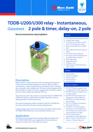
Figure 11.a illustrates a system with a reverse 3tJ fault with fault resistance. Figure 11.bshows the total AtJ fault current (IF,.). the prefault memory voltage (V .,m . AtJ voltage andcurrent seen by the relay (Vaf and IRLY,arespectively). and IRLY,aadjusted by the replica lineimpedance.Recall the denominator term of Equation I for a phase distance element. This denominatorterm is a directional element. It indicates how a phase distance element of infinite reachwould perform for this same fault. If the angle between Z.I and Vp is less than 90 , thephase distance element declares the fault forward. From Figure II. b, the angle betweenIRLY.Zand Va is less than 90 . Thus, after the memory voltage (Va.m- becomes in stepwith V sf, the directional security of the phase distance element is compromised.Figure 11.c illustrates the same reverse 3 pfault with load flowing out from the relay terminal(from Es towards EJ. For this case, the phase distance relay is secure even after the memoryvoltage becomes in-step with the fault voltage.eEsl.Q."' ELAY-2.s3-f I RLY -!m-ZS1ZL1ZR1"' ERi.§ .(a)IF RGIRLY.aVaJl1em(b)IRLY.aIF.aIRLY,a .ZL1Va. me 90.(REVERSE)(c)IFFigure II:Reverse 3f/ Fault Conditions and Mho Element Performance17
SolutionsI.2.3.4.5.Clear the 3 ! fault before the memory expires.The apparent impedance for the reverse 3 ! -Gfault enters the tripping characteristic inthe second-quadrant. Reducing the maximum torque angle reduces the amount ofsecond-quadrant coverage.Require an increased torque magnitude output from the comparator (i.e. , desensitize theelement). As the apparent impedance enters the tripping characteristic very near theorigin, forward direction 3 ! faults produce greater torques than do the reverse 3 ! faults.Add current offset in the positive direction to the polarizing reference.Test the angle between the positive-sequence current and voltage (i.e., use a positivesequence directional element). This angular test limits the three-phase fault coverage to a180 impedance angle sector of -120 to 60 .LOAD ENCROACHMENTThe impedance of heavy loads can actually be less than the impedance of some faults .Yet,the protection must be made selective enough to discriminate between load and fault conditions. Unbalance aids selectivity for all faults except three-phase faults.Figure 12 shows the load-encroachment characteristics in the impedance NEFigure12:Load Encroachmenton Mho Distance18ElementCharacteristics
When power flows out, the load impedance is in the wedge-shaped load-impedance area to theright of the X-axis. When power flows in, the load impedance is in the left-hand loadimpedance area.There is overlap (shaded solid) between the mho circle and the load areas. Should the loadimpedance lie in the shaded'area, the impedance relay will detect the under-impedancecondition and trip the heavily-loaded line. Such protection unnecessarily limits the loadcarrying capability of the line.For better load rejection, the mho circle can be squeezed into a lenticular or elliptical shape.Unfortunately, this also reduces the fault coverage.Alternatively, we could use additional comparators to make blinders parallel to the transmission line characteristic, to limit the impedance-plane coverage, and exclude load from thetripping characteristic.Or, we could build quadrilateralcharacteristics,which box-out load.All traditional solutions have the same common approach: shape the operating characteristicof the relay to avoid load. The traditional solutions have two major disadvantages:1.2.Reducing the size of the relay characteristic desensitizes the relay to faults with resistance. A voiding a small area of load encroachment often requires sacrificing much largerareas of fault coverage.From a user's point of view, the more complex shapes become hard to define, and therelays are harder to set.A new approach does not modify the relay characteristic shape directly.Instead, it definesthe load regions in the impedance plane, and blocks operation of distance elements if theimpedance is in either of the load regions.Figure 13 shows the new approach applied to a four-zone mho relay. The mho characteristicsare conventional, and are not modified to exclude load.19
xLOAT .RLOAT-.MAGNITUDELOAD-IN MAGNITUDEFigure 13: Improved Load-EncroachmentMethodThere are two load regions shown (1oad-in and load-out). The relay calculates the complexpositive-sequence impedance and tests it against the boundaries of these load regions. If theimpedance is inside either region, then the relay concludes the impedance represents load, andblocks the mho elements. If the impedance is outside both load regions, the mho elements arepermitted to operate.The advantages of the new approach include:I.Greater coverage for faults is possible because only the overlap between the loadcharacteristic and the relay characteristic is blocked.2.The load-encroachment characteristics are easy to set, because they can be directlyrelated to the maximum load conditions. Once we have maximum load-in and load-Outconditions, and the range of power factors of the load, the load-impedance areas can befound. No customization of relay characteristics is required to avoid load.3.Separate characteristics for load-in and load-out are easy to define.4.Since the characteristics for faults and loads are independent, there is less chance ofsetting errors .20
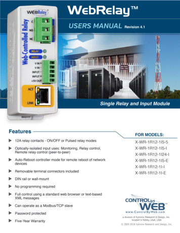
The logic applies to three-phase faults only. Load-encroachment blocking is not required ordesired for unbalanced faults (e.g., AB, BC, CA, AG, BG, CG, ABG, BCG, CAG faults).FAUL T -TYPE SELECTIONCONSIDERA TIONSFor security , distance relay schemes must consider the behavior of the distance elements in allsix fault loops (AG, BG, CG, AB, BC, and CA) under very broad and general system, load,and fault conditions.There are two major concerns:2.Ground distance elements can overreach for line-line-ground (LLG) faults.Phase distance elements can operate for close-in line-ground (La) faults.The first concern is generally considered a problem in all applications. The second concern isa problem in single-pole-trip schemes, and a targeting nuisance.How can we reliably prevent unwanted relay elements from interfering with the performanceof the overall scheme?If we know the fault is an AG fault, then we can block the AB and CA elements in order toavoid a three-pole trip for a LG fault.If we know the fault is a BCG fault, then we can block the BG and CG elements, avoidingpossible overreach by the BG and CG elements.(The BG element tends to overreach for a BCG fault with resistance to ground. The CGelement tends to overreach for a BCG fault with resistance between the phases.)SelectionUsinethe An2leBetweenL andI.,The angle between the negative-sequenceused and very useful indicator .current and the zero-sequence current is a frequentlyFigure 14 shows the sequence networks for AG and BCG faults. The symmetrical componentcurrents are referenced to phase A. That is, 10means lAO,and 12means IA2. For these twofaults, the angle between 12and 10is zero degrees. Figure 15 shows phasor diagrams for AG,BG, and CG faults. It also shows the phase relationships between 10and 12for the three .faults.21
APB9C90AeGROUNDrZ1Z20(AT THEFAULTPOINT)zo111012ABBBCBBC-GROUND(ATTHEFA T"'ii!1210Figure 14: 10and 12 Relationship for AG and BCG Faults (without Fault Resistance)\VA/VBVBVBIAAe GROUND CSGROUNO120 .""""12",,--/10j10J12Figure 15: 10and 12 Relationship for AG, BG, and CG Faults22
Given that the fault is a single-line-ground(SLG) fault, the angle between 10 and 12 in the faultis a very reliable indicator of the fault type: centered around zero degrees for AG, -120 forBG (12 lags 10 by 120 ), and 120 for CG (12 leads 10 by 120 ). Fortunately, these anglesdo not change much over a broad range of system conditions.Thinking about Figures 14 and 15 at the same time, we conclude:If the angle is near zero, then the fault is AG or BCG.If it is AG, then AB or CA could also pick up and three-pole trip for a single-line-groundfault.If it is BCG, then the BG and CG ground distance elements may overreach.THEREFORE:Enable AG, BC elements only.If the angle is near -120 , then the fault is BG or CAG.Enable BG and CA elements only.If the angle is near 120 , then the fault is CG or ABG.FaultEnable CG and AB elements only.One approach is to assign 120 sectors to AG, BG and CG faults. For example, anglesbetween :!:60 belong to AG and BCG faults.ResistanceCanAffectThisSchemeFigure 16 shows the effects of introducing fault resistance between the point where phases Band C are shorted together and ground. Rf
Distance Relay Element Design E. O. Schweitzer, III, and Jeff Roberts Schweitzer Engineering Laboratories, Inc. Published in the SEL Journal of Reliable Power, Volume 1, Number 1, July 2010 Previously presented at the V Seminário Técnico de Proteção e Controle, August 1995, 47th Annual Georgia Tech Protective Relaying Conference, April 1993,