Transcription
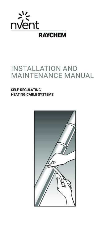
INSTALLATION ANDMAINTENANCE MANUALSELF-REGULATINGHEATING CABLE SYSTEMS
1General informationPg. 32Heating cable selectionPg. 53Heating cable installationPg. 54Components installationPg. 135ThermostatsPg. 186Thermal insulation and markingPg. 197Power supply and electrical protectionPg. 218Heating cable testingPg. 219Operation, maintenance and piperepairsPg. 2310 Heating cable damagePg. 2411 Troubleshooting guidePg. 242 nVent.com
1GENERAL INFORMATIONThe Installation and Maintenance manual is for nVentRAYCHEM self-regulating and power limiting heating cablesystems on thermally insulated pipes and vessels only.For information regarding other applications contact yournVent representative.BTV & XTV Self Regulating Heating CablesLN ower output varies with temperature.PAs pipe temperature increases, power output decreases. t high temperatures, the polymer expands, reducingAthe number of the conductive paths, and thus reducingcurrent flow. t low temperatures, there are many conductive paths,Aallowing current to flow between the conductors.ImportantFor the nVent warranty to apply, the instructions that areincluded in this manual and product packages must befollowed. The installation must be compatible with localrequirements applicable to electric heat-tracing systems.CertificateNoMarking1Ex e IIC T6 Gb XBTVTC RU C-BE.МЮ62.В.00054/18 1Ex e mb IIC T6 Gb XООО “ПРОММАШ ТЕСТ”Ex tb IIIC T80 C Db XEx tb mb IIIC T80 C Db X1Ex e IIC T* Gb XXTVTC RU C-BE.МЮ62.В.00054/18 1Ex e mb IIC T* Gb XООО “ПРОММАШ ТЕСТ”Ex tb IIIC T* Db XEx tb mb IIIC T* Db XnVent.com 3
BTVXTV–60 C T –20 C35 mm51 mm–20 C T –10 C30 mm35 mm–10 C T 0 C25 mm25 mm0 C T 10 C20 mm20 mmT 10 C12 mm12 mmMinimum Installation Temperature–60 C–60 CBTVXTVMaximum Maintain Temperature(power on)65 C120 CMaximum Exposure Temperature (1000hrs cumulative exposure power on)85 C250 C (*)Maximum Exposure Temperature(continuous power off)––Self-limiting Temperature in accordancewith EN62086-1 5.1.11T6T3(T2: 20XTV2)Power Limiting Temperature(*By design)–T*Minimum Bending Radius(*) The 250 C rating applies to all products printed “MAX SHORT-TERM EXPOSURE250С”.WarningAs with any electrical equipment or wiring installation operating at line voltages, heating cable and component damage or incorrect installation that allows the penetrationof moisture or contamination can lead to electrical tracking, arcing and potential firehazard.Do not connect heating cable conductors together or this will result in a short circuit.Any unconnected heating cable end must be sealed with a nVent approved end seal.To prevent fire or explosion in hazardous areas, verify that the maximum sheathtemperature of the heating cable is below the auto-ignition temperature of the gasesin the area. For further information, see design documentation.4 nVent.com
2HEATING CABLE SELECTIONCheck the design specification to make sure the properheating cable is installed on each pipe or vessel. Refer to nVentproduct literature and the TraceCalc software to select theproper heating cable for each thermal, chemical, electrical andmechanical environment.3 HEATING CABLE INSTALLATIONWarningDe-energise all power circuits before installation or servicingHeating cable storage eep ends of heating cable and kit components dry beforeKand during installation Temperature range: –40 C to 60 C Protect the heating cable from mechanical damageStorage and transportation of the heating cable should becarried out in accordance with GOST 18690-823.2 Pre-installation checksCheck materials received: eview the heating cable design and compare the list ofRmaterials to the catalogue numbers of heating cables andelectrical components received to confirm that propermaterials are on site. The heating cable type is printed on itsouter jacket. emperature exposure must not exceed that specified inTnVent product literature. Exceeding these limits will impairproduct performance. Check that expected exposure iswithin these limits. nsure that the heating cable voltage rating is suitable forEthe service voltage available. Do not energize cable when it is coiled or on the reel. I nspect heating cable and components for in-transitdamage. An insulation resistance test (see section 8) oneach reel is recommended.Check piping to be traced: nsure all pressure testing is complete and pipework hasEfinal paint coating. alk the system and plan the routing of the heating cable onWthe pipe. heck pipework against specification drawing. If differentCconsult design authority. I nspect piping for burrs, rough surfaces, sharp edges etc.which could damage the heating cable. Smooth off or coverwith layers of glass cloth tape or aluminium foil.nVent.com 5
3.3 Heating cable handlingHeating cable handling tips: aint and pipe coatings must be dry to the touch beforePheating cable installation. When pulling the heating cable, avoid:–– sharp edges–– excessive pulling force–– kinking and crushing–– walking on it, or running over it with equipmentHeating cable pulling tips: Use a reel holder that pays out smoothly with little tension. eep heating cable strung loosely but close to the pipeKbeing traced to avoid interference with supports andequipment. ay out designed length and mark (i.e. with fixing tape) onPcable while still on reel. eave the appropriate amount of heating cable at all powerLconnection, splice, tee and end seal locations.(Refer to component installation instructions)–– A dd additional heating cable to trace the fittings andsupports or for spiralling as required by the designspecifications, or consult nVent product literature fordesign. rotect all heating cable ends from moisture, contaminationPand mechanical damage or other interference if left exposedbefore component installation.3.4 Heating cable attachment recommendations he heating cable may be installed straight, spiralled or inTmultiple runs as required by the design specification, nVentproduct literature or TraceCalc software.–– D o not use metal attachments, vinyl electrical tape or ducttape as heating cable damage may result.–– S elf-Regulating technology allows for the multipleoverlapping of the heating cable on to itself. ix in place with a minimum of two wraps the appropriateFself-adhesive glass cloth tape (see figure 1) or plastic cableties at 300 mm intervals and additionally where necessary. lastic cable ties must have a temperature rating thatPmatches the system exposure temperature. he heating cable’s minimum bend radius must not beTexceeded (refer to p. 2)6 nVent.com
Bend the cable only in upright position he heating cable does not bend easily in the flat plane.TDo not force such a bend, as the heating cable may bedamaged.3.4.1 Straight tracing traight trace the pipe unless the design calls for spirallingS(see 3.4.2). n horizontal pipes fix on lower quadrant as shown in FigureO1 and not on bottom of pipe. o prevent overheating, be sure the location of the powerTlimiting heating cable is planned so that the active heatingzone will not extend into the component. Read the kitinstallation instructions and plan the component locationbefore permanently attaching the cable to the pipe. Ensurethat the active heating zones are located where heat isrequired i.e. on the pipe. Thermally insulate and weatherproof to specification.Figure 1300mmTopPipeGlass cloth tape(typical)Tight on pipeThermalinsulation(typical)45 (nominal)nVent attachment tapes:GT66 Self-adhesive glass cloth tapeGeneral purpose tape. Not for stainless-steel surfacesor for installation temperatures 4 C.nVent.com 7
GS54 Self-adhesive glass cloth tapeRecommended for use on stainless-steel and cupranickel surfaces or for installation temperatures 4 C.Figure 2ATE-180 Aluminium tapeUse only if the design requires it.ATE-180 improves the heat transfer and increases the poweroutput of the heating cable.Attach the heating cable to the pipe as shown in Figure 2.3.4.2. Spiral tracing lternative spiralling methods are shown inAFigures 2a and 2b. Only spiral heating cable on pipe when called for by design. o prevent overheating, be sure the location of the powerTlimiting heating cable is planned so that the active heatingzone will not extend into the component. Read the kitinstallation instructions and plan the component locationbefore permanently attaching the cable to the pipe. Ensurethat the active heating zones are located where heat isrequired i.e. on the pipe.Spiral Pitch Table (mm).NBNPSSpiral Ratio(mm)(inches)Metres of cable per metre of 1808106505504802008152010508407106208 nVent.com
Example:For pipe of 80 mm NB (3” NPS) requiring 1.3 metres of heatingcable per metre of pipe, pitch is 350 mm.Figure 2aPipe lengthGlass cloth tape(typical)PitchHeatingcablePipeApply glasscloth tapebefore spirallingcable on pipeWrap loops inoppositedirectionTape afterspiralling cableon pipeHeating cable lengthHeating cable length pipe length x spiral ratioRefer to design specification for spiral ratioStep 1Make starting loop as shownStep 2Grasp loop and wind around pipeStep 3Space evenly and attach to pipe.Thermally insulate and weatherproof to specificationFigure 2bHeating cableGlass cloth tape(typical)PitchPipeRefer to design specification for spiral pitchMark the pipe at the spiral pitch or use a simple length gaugeFix the heating cable as installation progressesThermally insulate and weatherproof to specification3.5 Cutting the heating cable ut the heating cable to length after it is attached to theCpipe. Before cutting it, confirm the tracing allowance as perSections 3.3 and 3.6. AYCHEM heating cable can be cut to length withoutRaffecting the heat output per metre.3.6 Typical installation details ypical installation details for fixing heating cable to pipeTfittings are shown hereafter.nVent.com 9
General notes: Trace pipe fittings as shown to allow easy maintenance. onsult the design specification or nVent product literatureCor TraceCalc software for the tracing requirements forfittings and supports. ollow the recommendations for cutting and strippingFheating cables; they are included in the componentinstallation instructions.3.6.1 ValveFigure 3PipeValve bodyHeating cableGlass tapeThe heating cable configuration willvary for different valve shapes andheating cable lenghts. efer to design specification for additional heating cableRlength. Fix with self-adhesive glass cloth tape. hermally insulate and weatherproof to specificationT(including valve stem).3.6.2 ElbowFigure 4PipeGlass cloth tape(typical)Heating cableThermal insulation10 nVent.com
Fix heating cable to outside (long) radius of elbow Fix with self-adhesive glass cloth tape Thermally insulate and weatherproof to specification3.6.3 FlangeFigure 5PipeGlass cloth tape (typical)Heating cable dditional heating cable is 2-3 times diameter of pipeA(typical) Fix with self-adhesive glass cloth pipe Thermally insulate and weatherproof to specification3.6.4 Pipe bar hangerFigure 6Bar hangerSealerWeatherproofingThermal insulationPipeHeating cableBar hangerSealerGlass cloth tape(typical)Heating cablenVent.com 11
–– D o not clamp heating cable with support. Heating cablemust be over the support o additional heating cable is required for bar or rod pipeNhangers unless called for in the design specification, thenuse loop length specified ix with self-adhesive glass cloth tapeFThermally insulate and weatherproof to specification3.6.5 Pipe support shoeFigure 7Side viewGlass cloth tape(typical)Support shoePipeView from underHeating cablePipe efer to design specification for additional heating cableRlength Fix with self-adhesive glass cloth tape Thermally insulate and weatherproof to specification12 nVent.com
4COMPONENTS INSTALLATIONGeneral notes:Select the required components from nVent product literature oruse the TraceCalc software.RAYCHEM component kits (including power connections,splices and end seals) must be used to satisfy Standards andApproval Body requirements.Installation instructions included in the kit must be followed,including those for preparation of the heating cable conductorsfor connections. Before assembly, use the guide given in theinstructions to ensure that the kit is correct for the heatingcable and environment.–– R AYCHEM self-regulating and power limiting heatingcables are parallel circuit design. Do not twist theconductors together as this will result in a short circuit.4.1 Components required or the installation of all components refer to the relevantFcomponent installation instructions. equired for each heating cable run:RPower connection and insulation entry kitEnd seal. As required:Splice. Tee-splice. Junction box. Three connection kits andthree insulation entry kits. Accessories (pipe straps, fixingtape, support brackets, labels, etc.).nVent.com 13
4.2 Typical systemsFigure 8aWallmountedIEK-25-04Insulation entry kitValveJBU-100Junction box formodular systemC25-100Connection kitSB-100Heating cableJBU-100Splice (as required)Thermal insulationGlass cloth tape(typical)Heating cableInsulationEntry kitSB-101End sealThermostat14 nVent.comnVent.com 15
Figure 8bE-100-LLighted end sealJBM-100Integrated power/tee con nec tionE-100End sealT-100Tee or splicecon nec tionS-150Low profile spliceJBS-100Integrated power con nec tion(shown with light)E-150Low profileend sealC-150Low profile power connectionIEK-25-04Insulation entry kit16 nVent.comnVent.com 17
4.3 Component installation hints n horizontal pipes locate junction boxes below pipeOwherever possible. Pinch out drainhole in the stand wheninstalling upside down. ocate junction boxes for easy access but not exposed toLmechanical abuse. osition junction boxes so that power cable and heatingPcable entries do not point upwards.JBS-100-L-EPIntegrated power connection(with earth plate and light) Fix lids in place where access not required. onfirm junction box stopping plugs are correct forCapplication and fixed firmly in place. oute heating cable from junction box to insulation entry soRas to avoid possible mechanical damage.–– D o not strain heating cable as it exits/enters junctionboxes and insulation entries. nsure heating cable is fixed above pipe straps such as usedEfor junction box support brackets. ix all low profile components (e.g. heatshrink end seals) inFplace with self-adhesive glass cloth tape.5THERMOSTATS I n temperature-sensitive applications, thermostatic controlmay be necessary. If maximum temperature is a concern,consult your nVent representative for design assistance. ollow the installation instructions supplied with theFthermostat. Use the proper wiring diagram for the heatingcable layout and control method desired.18 nVent.com
6THERMAL INSULATION AND MARKING6.1 Pre-insulation checks isually inspect the heating cable and componentsVfor correct installation and damage. (See Section 10 ifdamaged.) I nsulation resistance (Megger) testing (as per Section 8) isrecommended prior to covering the pipe with thermalinsulation.6.2 Insulation installation hints orrect temperature maintenance requires properly installedCand dry thermal insulation. Thermally insulate and weatherproof to design specification. heck insulation type and thickness against the designCspecification. o minimize potential heating cable damage, insulate asTsoon as possible after tracing. heck that all pipework, including fittings, wall penetrationsCand other areas, have been completely insulated. nsure that heating cable is not damaged during installationEof cladding for example by drills, self tapping screws andsharp edges of cladding. heck that all insulation entry kits are fitted correctly andCsealed. nsure that all places where valve stems, support brackets,Ethermostat capillaries, etc exit the cladding are sealed.nVent.com 19
6.3 Marking or power limiting heating cable install label: LAB-I-35 asFshown (typical) in figures 10a & 10bFigure 10a060dse0 0 IIergifnenöfS -1 x e U ile enng ionJ B 2 G EE 1058 en whannutensXII ATEX t op r Spsous02no te ir10.D. 199XB 97 Do t unouvr-95PTsEx 96D3XNichpa03B Nr. . Ex10NePTS No.D. 8XBAT6II CV de T6BT EEX e IIxT4EEII CVR de T4QT EEX e IIx)T2 (T2EEII C6 CV de 223KT EEX e IIV-TxEE 15XTC T3,12 II8, de T34, EEX e IIxEE 2 C T2 (T2)CV-T IIXT de 0 20 EEX e II 25xEE19-95Ex 96D3ExX04B Nr. .10PTS No.D. 200XBA-95Ex 96D3X05B Nr. . Ex10PTS No.D. 435XBA-95Ex 96D3X05B Nr. . Ex10PTS No.D. 5X 47BA-95 43 16Ex 95D3 55PRB Nr. ExPTS NoBALAB-I-35Figure 10bLAB-I-35 he presence of the heating cables shall be made evidentTby the posting of warning labels or caution labels (“ElectricTraced”) on the cladding. Labels are to be applied atmaximum 3 meter intervals and on alternate locations alongthe circuit. I nstall “Electric Traced” signs along piping at suitableintervals(3 m intervals recommended) on alternate sides as awarning. ark on outside of insulation the location of heating cableMcomponents. or XTV and KTV heating cables if T-class complianceFwas proven by stabilized design: install LAB-EX-XTV-KTValuminium tag at approximately 75 mm from the entry of thejunction box.Figure 10cmm 75-20 nVent.com
7 POWER SUPPLY AND ELECTRICALPROTECTION7.1 Electrical loadingSize overcurrent protective devices according to the designspecification or applicable nVent product literature. If devicesother than those specifically identified are used, consult thenVent representative for the appropriate sizing information.7.2 Ground fault equipment protection is required foreach circuitThe metal sheath/braid of the heating cable must be connectedto a suitable earthing terminal7.3 Residual current (earth fault) protectionnVent insists on the use of a 30 mA residual current device toprovide maximum safety and protection. However, where thereis a marked increase in nuisance tripping, a maximum 300 mAresidual current device may be used.For heating cables installed in a hazardous area, the useof residual current devices is normally a condition of theirapproval.8HEATING CABLE TESTING8.1 RecommendationsnVent recommends insulation resistance test before installingheating cable; before installing thermal insulation; prior to initialstart-up; and as part of the periodic maintenance.(see Section 9.2).8.2 Test methodAfter completing heating cable installation, the insulationresistance between the conductors and the braid should bechecked (see Figure 11) using a 2.500 VDC megger. Minimumreadings should be 10 Megohms regardless of the heatingcable length. The installer should record the original values foreach circuit on the installation record sheet (see page 25). If athermostat is installed, it should be bypassed.nVent.com 21
Figure 11Test between heating cable and braid22 nVent.com
9 OPERATION, MAINTENANCE AND PIPEREPAIRS9.1 Heating cable operation–– T emperature exposure must not exceed that specified innVent product literature. Exceeding those limitations willshorten the service life and may permanently damage theheating cable. ipe insulation must be complete and dry to maintain thePcorrect temperature.9.2 Inspection and maintenance isual inspection: Exposed heating cable and pipe insulationVshould be checked periodically to make sure that no physicaldamage has occured. eggering: The system should be meggered regularly. WhenMmeggering the insulation resistance from the main supplypanel, it is recommended that the test is performed betweenL/N (together) and PE. Freeze protection systems should bemeggered before the winter months each year (see section8). Temperature maintenance systems should be tested atleast twice a year. Function testing of electrical protectionand temperature control systems should be carried out atregular intervals. he Periodic Inspection Record on the following pagesTshould be filled out during maintenance of each circuit inyour system.9.3 Piping systems repair and maintenance Isolate heating cable circuit. rotect the heating cable from mechanical or thermalPdamage during pipe repair work. heck heating cable installation after pipe repairs andCrestore thermal insulation following the recommendations inSection 6. Check correct functioning of electrical protectionsystems.nVent.com 23
10 HEATING CABLE DAMAGE o not repair damaged heating cable.DRemove entire damaged section and splice in a new lengthusing the appropriate RAYCHEM splice kits. eplace damaged heating cable at once.RDamage allowing moisture and contamination to enter theheating cable may result in arcing earth faults and potentialfire hazards. eating cable exposed to fire or flame may cause further fireHdamage if powered.Remove from service at once and replace before re-use.11 TROUBLESHOOTING GUIDE efer to the Troubleshooting guide on pages 32-34.RIf the problem persists after following the guide procedures,contact your nVent representative immediately.24 nVent.com
nVent.com 25REMARKS & COMMENTS:Locations of low profile componentsare marked on the claddingInsulation complete and sealedCircuit voltageMegger test after insulating (bypassthermostat if applicable)Megger test on pipe before insulating(bypass thermostat if applicable)Drawing reference numberCircuit breaker numberINSTALLATION RECORDS FOR:DateInitialDateInitialConnection CINSTALLATION RECORD SHEETO.IT NIRCU
Thermostats set properly and capillaries are protectedIn connection systemsHeating cable and cable glands tightConnection terminals tightEarth connection tightInsulation in good conditionNo signs of overheating, moisture, orcorrosion, etc.MAINTENANCE CHECKS ION AND MAINTENANCE RECORD SHEETO.IT NIRCUC26 nVent.comYR.:
nVent.com 27REMARKS & COMMENTS:Locations of low profile componentsare marked on the claddingAll boxes and thermostats have beenfirmly closedCircuit voltageMegger test (bypass thermostat ifapplicable)DateInitialDateInitialConnection terminalsPanelDateInitialReading
Troubleshooting guideASymptom: Overcurrent protection trips or blowsProbable Causes1Electrical fault ata damaged heating cableb faulty splices or teesc end seald connection2Circuit oversized3Start-up below design temperature4Defective electrical protectionB Symptom: RCD tripsProbable Causes1Earth fault at:a damaged heating cableb faulty splices or teesc end seald connection2Excessive moisture in:a junction boxesb splices and teesc end seals3 High leakage currents due to a combinationof excessivelengths of power cable and heating cable.4Mains borne disturbances5Defective RCD28 nVent.com
Corrective Actions1 Investigate and remedy (see note 1):2Resize or redesign within Technical DatabookGuidelines. (If larger protection is required,ensure supply cables are compatible).3abc4redesign for lower start-up temperaturesp reheat pipe from alternative heat source to within exposure temperatures given in ProductData Sheets Energize part of circuit followed by remainder(e.g. in sequenceReplaceCorrective Actions1Investigate and remedy (see note 1):2Dry out and reseal or remake immediately.Perform insulation resistance test.(10 MΩ minimum)3Redesign4Redesign distribution, guidance is available fromnVent5ReplacenVent.com 29
C Symptom: No power output.Probable Causes1Loss of supply voltage due to:a overcurrent or residual current protection operatingb loose terminals in junction boxc loss of supply cable continuity (e.g., open circuitedfrom damage2Control thermostat is connected in the normallyopen position3High resistance connection at:a junction box terminalsb splices and teesD Symptom: Low pipe temperature.Probable Causes1Wet thermal insulation2Design error3Incorrect setting or operation of controls e.g.,thermostats.4Heating cable has been exposed to excessivetemperature beyond rating.Note:Locate faults by the following steps:1 Visually inspect the power connections, splices and end seals forcorrect installation.2 Look for signs of damage at:a) Valves, pumps, flanges and supports.b) Areas where repairs or maintenance work has been carried out.3 Look for crushed or damaged insulation and cladding along the pipe.30 nVent.com
Corrective Actions1Restore supply voltagea following A and B (page 31)b r e-tighten terminalsNB: If excessive heating has occured due to highresistance, replace terminals or crimpsc locate damage and repair2Reconnect to normally closed position3Locate and remedy by:a re-tightenb r epairNB: If excessive heating has occured due to highresistance, replace terminals or crimpsCorrective Actions1Remove and replace with dry insulation of correctspecification and ensure complete weatherproofing2a check with competent authority for design conditionsb modify to meet nVentrecommendations3Repair or reset to correct level of operation4Replace4 If after 1, 2 and 3 above the fault has not been located, then either:a) Consult nVent for futher assistance.b) W here local practices and conditions allow (e.g., non hazardousareas) isolate one section of heating cable from another by cuttingin half and testing (e.g., Insulation Resistance) both halves untilgeneral area of damage is found. Remove insulation and expose fault.nVent.com 31
Republic of KazakhstanTel. 7 712232 09 68Fax 7 7122 32 55 54saleskz@nVent.comРоссияТел. 7 495 926 18 85Факс 97 495 926 18 86salesru@nVent.comnVent.com 2019 nVent. All nVent marks and logos are owned or licensed by nVent Services GmbH or its affiliates.All other trademarks are the property of their respective owners. nVent reserves the right to changespecifications without notice.Raychem-IM-EU1499-SRcableMIR-EN-190532 nVent.comPCN 481825-000
3 Heating cable installation Pg. 5 4 Components installation Pg. 13 5 Thermostats Pg. 18 6 Thermal insulation and marking Pg. 19 7 Power supply and electrical protection Pg. 21 8 Heating cable testing Pg. 21 9 Operation, maintenance and pipe repairs Pg. 23 10 Heating cable damag


